

Page 1

HAND-HELD RESPIRATORY
MECHANICS MONITOR
Service Manual
Model 101
April 17, 2000
Catalog No. 6800-90-01
Novametrix Medical Systems Inc.
PO Box 690
5 Technology Drive
Wallingford, Connecticut, U.S.A. 06492
Page 2

Page 3

Revision History
Revision History
22-May-98 Release
17-Apr-00 Revision 01, R-N746
Rev. 01
Model 101 Service Manual
iii
Page 4

[This page intentionally blank.]
Revision History
iv
Model 101 Service Manual
Rev. 01
Page 5

Table of Contents
y
Safety ..................................................................................................... 1
Introduction ...........................................................................................3
Keypad Controls and Indicators ........................................................................4
S
mbols ............................................................................................................. 4
Theory of Operati on ............................ .......... ........... .......... ........... .......5
Main Board ........................................................................................................5
Power Su pply ................. ..................... .................... ..................... ........... ....................5
Reference Voltages .............................. ................ .. ................ ................ ................ .....5
Battery Charger ...........................................................................................................5
On/Off Co n tr ol .. ... ........... ............ .................... ..................... .................... ............ ........6
Digital Control and Microprocessor ...................................... .. .. ................. .. .. .. ............6
Serial Communication .................................................................................................7
Audio ...........................................................................................................................7
Interface ......................................................................................................................8
Analog Control Signals ................................................................................................8
Sensor Identification ....................................................................................................8
Flow Zeroing ...............................................................................................................8
Flow Circuitry ..............................................................................................................9
Baromet ric a nd A ir w a y P re s s u re .... .. ..................... ..................... .................... ...........10
Interface Board ................................................................................................11
Key panel Interface . .................................................................................................. 11
Display interface ........................................................................................................11
LED control ...............................................................................................................11
Power Su pplies ....................... ..................... ..................... .................... ............ ........11
Functional Tes ts ................... ........... ............................. .......... ........... .13
Equipment Required ........................................................................................13
Procedure ........................................................................................................ 13
Accuracy Tests ............................................ .. .. ....... .. .. .... .. .. .. ....... .. .... .15
Equipment Required ........................................................................................15
Procedure ........................................................................................................ 15
Electrical Tests ...................................................................................17
Equipment Required ........................................................................................17
Rev. 01
Model 101 Service Manual
v
Page 6

Table of Contents
g
y
Procedure ........................................................................................................ 17
Power Supp lies ........ ............ .................... ..................... .................... ............ ............17
Airway Pre s s u re Ca l ib ra tion . .. .. ..................... .................... ..................... ........... ........18
Differen t ia l P re s s ur e Calibration ............ .. ..................... ........... ..................... ........... . 19
Barometric Pressure Calibration .....................................................................19
Maintenance ........................................................................................21
General ...........................................................................................................21
Maintenance Schedules .................................................................................. 21
Cleanin
Batter
Battery Installation .................................................................................................... 23
External B a ttery Char ger ........... ... .. ..................... .................... ............ .................... . 23
Features Connector .............. .. .................. .. ............... .. .................. .................. .. .......23
and Sterilization ................................................................................22
and AC Operation ............................................................................... 22
Assembly Exchanges ...................................................................................... 24
Disassembling the Monitor ........................................................................................ 24
Reassembling the monitor ........................................................................................ 26
Accessories ......................................................................................... 27
Parts Lists ............................................................................................29
6800-00 Final Assembly, Model 101 ............ .................. .................. .................. .......29
6800-01 Main Assembly, Model 101 ................ .. ................................................... .. ..29
2740-01 01 Main Board Assy, Model 101 ........................ .................. .......................30
2740-17 01 Main Board Subassy, Model 101 ......................................................... ..30
2739-01 00 Battery & Comm Interface Board Assy ..................................................32
2741-01 00 Interface Boa rd Assy, Model 101 .............................. .. .............. .............32
6935-48 00 Test Fixture, Flow Leak Test ................................................................. 33
Drawings and Sche matics ................... ........... .......... ........... .......... ....35
vi
Model 101 Service Manual
Rev. 01
Page 7

Guarantee
Equipment manufactured or distributed by Novametrix Medical Systems Inc., is fully guaranteed,
covering materials and workmanship, for a period of one year from the date of shipment, except for
certain dispo sable pr oducts and products wit h stated gu arantees other than one year. Novametrix r eserve s
the right to per form gu ara ntee s ervi ce(s) at it s f actor y, at an authorized rep air s tati on, o r at t he cus tome r’s
installation.
Novametrix’ obligations under this guarantee are limited to repairs, or at Novametrix’ option,
replacement of any defective parts of our equipment, except fuses, b atteries, and calibration gasses,
without charge, if said defects occur during normal service.
Claims fo r damage s durin g shipme nt must be filed pro mptly wi th the tr ansportati on compa ny. All
correspond ence co ncerning the equ ip ment must specify bot h t he model name and number, an d t he serial
number as it appears on the equipment.
Improper use, mishandling, tampering with, or operation of the equipment without following specific
operating instructions will void this guarantee and release Novametrix from any further guarantee
obligations.
Service Department
For factory repair service, call toll free
1-800-243-3444
In Connecticut, call Col lect (2 03) 265-7701
(203) 284-0753
FAX
http://www.novametrix.com
techline@novametrix.com
Email
Caution:
license d medical practitioner.
Copyright 1998, 2000 Novametrix Medical Systems Inc. This document contains information which
is proprietary and the property of Novametrix Medical Systems Inc., and may not be reproduced, stored
in a retrieval system, translated, transcribed, or transmitted, in any form, or by any means, without prior
explicit written pe rmissio n from Novametrix Medical Systems Inc.
Federal (U.S.A.) law restricts this device to sale, distribution, or use by or on the order of a
Declaration of Conformity with European Union Directive
The Authorized Representative for Novametrix equipment is:
D.R.M. Green
European Compliance Services Limited
Oakdene House
Oak Road
Watchfield
Swindon, Wilts SN6 8TD
Rev. 01 Model 101 Service Manual
vii
Page 8

Guarantee
Service Policy
Novametrix Medical Systems Inc. provides 24-hour a day access to technical support through its
Technical Suppo rt Depa rtment in Wallingford, C onnecti cut, and company S ervice Re presen tatives
located throug hout th e United Sta tes. (Outside the U.S., prim ary technica l suppor t is handled t hrough ou r
qualified international sales and service distributors.)
Novamet ri x wil l provide Warranty Service suppor t wi thi n 48 ho urs of receiv in g a re quest for assistanc e.
Contact the Technical Support Department by telephone toll free at 800- 243 -3444, or 203-265-7701; by
facsimile at 203-284-0753; or, by e-mail at techline@novametrix.com. After hours telephone support
requests (before 8:00 AM and after 5:00 PM Eastern Time) will be responded to promptly by the
Technical Support on-call staff. After hours facsimile and e-mail requests will be answered the next
busines s day. It is suggested tha t an y perso n cal ling in for techni cal su pport h a ve t he equi pmen t a va ilabl e
for product identification and preliminary troubleshooting.
Novamet ri x reserves the right to repair or replace any product found to be defective during the warr ant y
period. Repair may be provided in the form of replacement exchange parts or accessories, on-site
technical repair assistance or complete system exchanges. Repairs provided due to product abuse or
misuse will be considered “non-warranty” and invoiced at the prevailing se rvice rate. Repl aced or
exchanged materials are expected to be returned to Novametrix within 10 days in order to avoid
(additional) charges. Return materials should be cleaned as necessary and sent directly to Novametrix
using the r et urn paperwork an d shipping label ( s) provided. (Transferri ng r et u rn m at eri al s t o a local sale s
or dealer representatives does not absolve you of your return responsibility.)
Novametrix manufactures equipment that is generally field serviceable. When repair parts are provided,
the recipient can call Technical Support for parts replacement assistance and repair assurance. In the
event a replacement part requires increased technical ca pability, Technical Support may request
Biomedical assistance, provide on-site technical suppo rt or complete replaceme nt equipment. If the
customer requires the return of their original product, the exchange material will be considered “loaner
material” and exchanged again after the customer equipment is repaired.
Novametrix promotes customer part icipation in w arranty repairs, should they beco me necessary. A
longer useful product life, and quicker, more cost-effective maintenance and repair cycles—both during
and after the warranty period, are benefits of a smooth transition into self-maintenance. The Technical
Support Department can provide technical product support at a level appropriate to your protocol and
budget requirements.
Please contact Technical Support for information on these additional programs and services:
• Focus Series Technical Training Seminars
• Test Equipment and Test Kits
• Service Contract / Parts Insurance Plans
• On-Site Technical Support
•“Demand Services” including
Flat rate parts -exchange
Flat rate return for repair
Time and Material
• Full warranty, discounted replacement sensors
Model 101 Service Manual Rev. 01
viii
Page 9

Section 1
The VENT✔ Handneld Resp iratory Mecha nics Monitor, Model 10 1, is electrically is olated. Patient
leakage current flowing from the instrument to ground is limited to less than 10 uA.
• Keep the VENT✔ and its accessories clean. Do not operate the VENT✔ when it is wet due to sp ills
or condensation.
• Connect only Novametrix Series 3 Flow Sensors to the VENT✔. For maximum performa nce ; keep
the pressure sensor ports oriented upward, and keep the sensor clear of moisture and secretions by
proper breathing circuit maintenance.
• Connect the sensor first to the VENT✔ and then to the patient breathing cir cuit in order to limi t
circuit volume loss and to avoid excessive moisture build-up in the flow sensor tubing.
• VENT✔ has electrically isolated inputs. Patient leakage current flowing from the instrument to
ground is limit ed to less than 10 µA at 120 V, 60 Hz. Pa tient iso lati on is grea ter t han 1 0 MΩ, 2500V
rms at 60 Hz.
• Where electr omagnetic devic es (i.e., ele ctrocautery) ar e used, patient monitoring may be interrupted
due to electromagnetic interference. Electromagnetic fields up to 3 V/m will not adversely affect
system performance.
• VENT✔ contains no user serviceable parts. Refer servicing to qualified service personnel.
• This product and its accessories which have patient contact are latex free.
For maximum patient and operator safety, observe the following warnings and cautions.
Safety
WARNINGS
!
Indicates a potentially harmful condition that can lead to personal injury.
Explosion Haza rd:
•
instrument in such an environment may present an explosion hazard.
Electrical Sho ck Hazard:
•
monitor or sensor. Refer servicing to qualified service personnel.
Fire Hazard:
•
Use in such an environment may present a fire hazard.
Failure of Operatio n:
•
has been corrected by qualified personnel.
• Do not apply tension to t he sensor tubing whi le connected to a patie nt breathing ci rcuit, as accid ental
extubation may result.
• Do not position the flow sensor’s tubing in any manner that may cause entanglement or
strangulation.
• Use the optional external battery charger in non-patient areas only.
Do NOT use the VENT✔ in the presence of flammable anesthetics. Use of this
Always turn the monitor off befor e c le ani ng i t. Do NOT us e a damaged
The VENT✔ should not be exposed to elevated oxygen levels at elevated pressures.
If the monitor fails to respond as described, do not use it until the situation
Rev. 01
Model 101 Service
Manual
1
Page 10

Section 1
CAUTIONS
Indicates a condition that may lead to equipment damage or malfunction.
• Federal (U.S.A.) law re stri cts th is devi ce to sal e, dist ribut ion, or us e by or on the order of a licens ed
medical practitioner.
• Electrical Shock Hazard: Always turn the monitor off before cleaning. Do NOT use a damaged
monitor.
• Do NOT use a damaged flow sensor.
• Do NOT immerse the monito r or senso rs in liquids.
• Do NOT sterilize the monitor or the sensors.
• No user serviceable parts inside. Refer servicing to qualified service personnel.
• Operate at temp era tu res between +10° C to +40° C (50-104° F), < 90% relative humidity (non-
condensing).
• Avoid storing the monitor at temp eratures less than -20° C or greater than +55° C (<-4° F or >131°
F).
NOTES
Indicates points of particular interest or emphasis for more efficient or convenient operation.
• The VENT✔ operates with Novametrix Series 3 Flow Sensors only.
• The VENT✔ performs an automatic zero (self calibration) periodically and as needed. During this
time, monitoring is interru pted for le ss than th ree seconds.
• The automatic zero can be manually initiated by simultaneously pressing the DATA and GRAPH
keys. After cha ngi ng th e sensor from Adult to Neon at al ( whil e t he VENT✔ is operation al ), w ai t 30
seconds then perform an automatic zero.
• This product and its accessories which have patient contact are free of latex.
• The C
• To determine the VENT✔ software version, turn the monitor on. During the self test performed at
power up, the softwar e lev el is sho wn on the thir d line as “main-101-xx”, where “xx” is the software
version.
• Some VENT✔ monitors were produced with the statement “Use only Novamet rix approved devic es,
13 VDC, 1A” located on the label at the Flow Sensor Input Connector. This erroneous statement
does NOT apply to the VENT✔ monitor and should be ignored.
/C Compliance Ratio (neonatal) parameter is not supported.
20
2
Model 101 Service
Manual Rev. 01
Page 11
Section 2
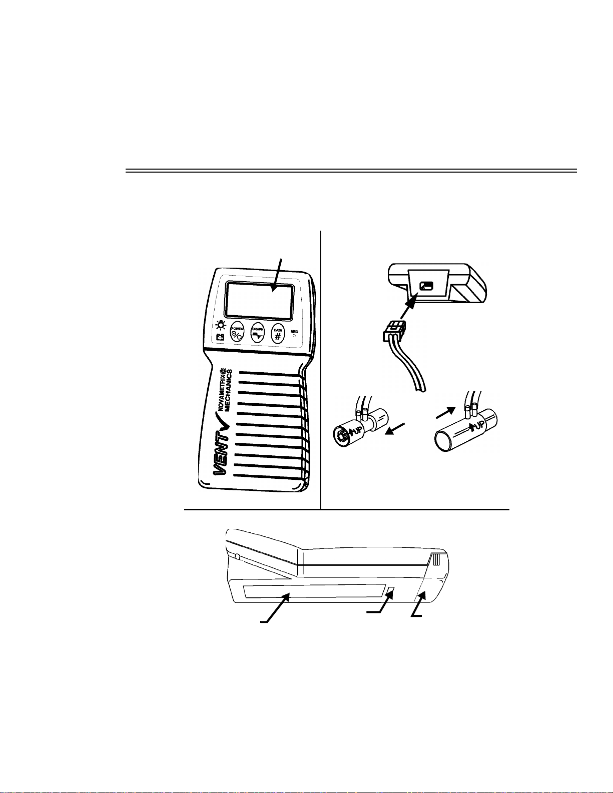
The VENT✔ Handheld Respiratory Mechanics Monitor, Model 101 is shown below.
Keypad &
Display
Introduction
Connect Series 3
Flow Sensor
t
n
e
i
t
a
P
o
T
r
o
t
a
l
i
t
n
e
V
o
Neonatal Pediatric/Adult
Sensor
#6718/6720
T
Sensor
#6717
Features
Quick Guide
Rev. 01
Connector
Battery Access
Compartment
Model 101 Service
Manual
3
Page 12
Section 2
g
g
g
g
g
g
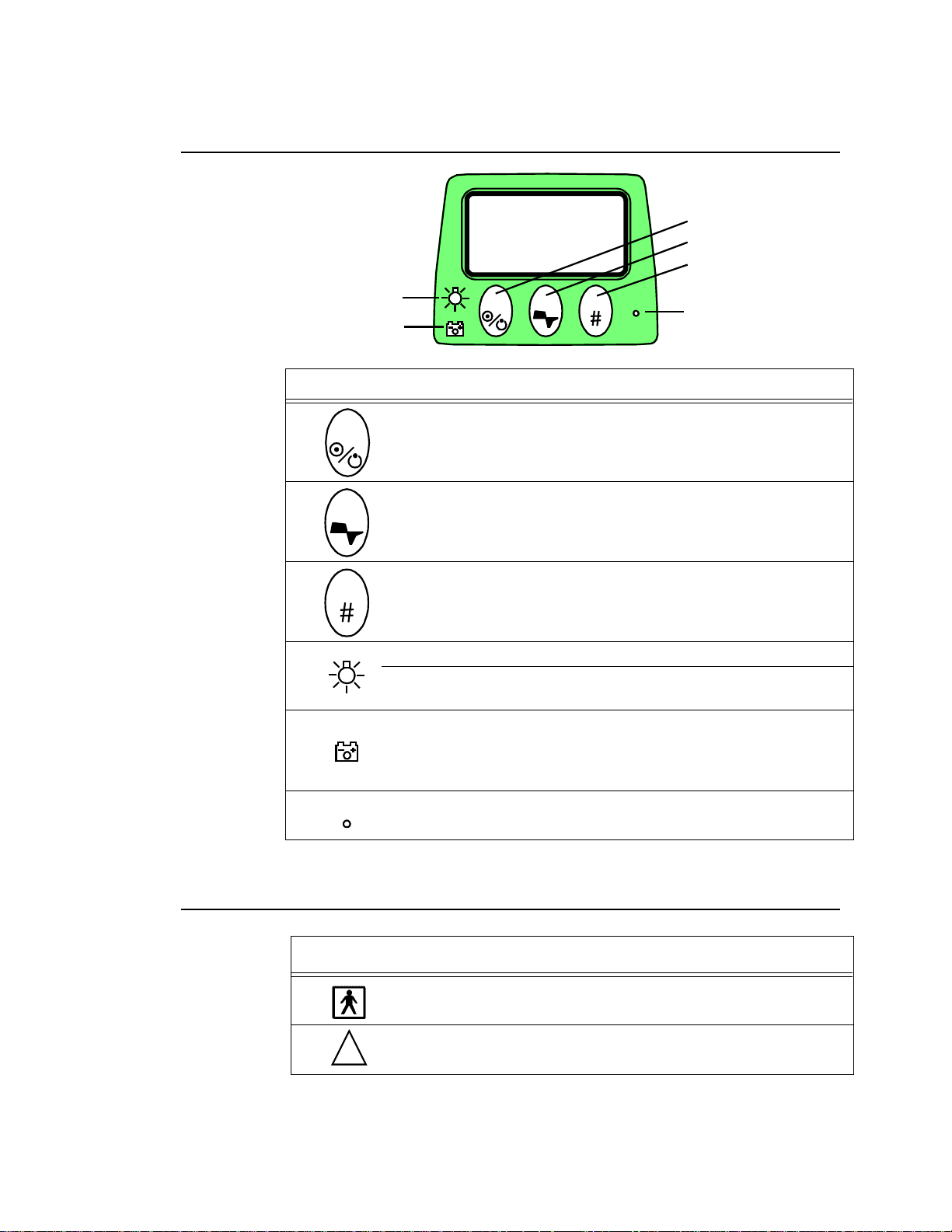
Keypad Controls and Indicators
2.1 Keypad Controls and Indicators
1
2
3
4
POWER GRAPH DATA
A
# Key Action Function
POWER
1 Press Turns
GRAPH
2Press
DATA
3Press
Press Turns displ ay backlight on/off.
4
Press &
Hold
A None
VENT
Display Graph Screens.
Additional presses caus es
h available Graph Screens.
throu
Display Data Screens.
Additional presses caus es
h available Data Screens.
throu
Adjusts contrast/viewin
(1 step/sec.)
Illuminated if powered from battery
Green; battery char
Yellow flash in
Red flashin
NEO
B
✔ on/off.
✔ to sequence
VENT
✔ to sequence
VENT
angle of display
ed
slowly; capacity getting low
quickly; exhausted in 10-15 min.
4
Model 101 Service
NEO
B None Illuminates when a Neonatal sensor is connected.
2.2
Symbols
Symbol Description
Patient Iso lation
Identifies patient isolation connection as type BF.
!
Manual Rev. 01
Attention
Consult manual for detailed information.
Page 13

Section 3
3.1 Main Board
3.1.1 Power Supply
Refer to page 4 of the schematic 2740-03. An external power source can be connected to J403 to power
the monitor and charge a rechargeable battery (only Novametrix approved rechargeable batteries and
chargers should be used with the model 101). The internal battery connects to the cathode of D11, fuse
F1 provides overload protection. Since the monitor has the possibility of being powered by the internal
battery or an external charger, diodes D4 and D11 isolate each of these sources from one another.
3.1.2 Reference Voltages
Refer to page 5 of the 2740-03 schematic. A 2.5 volt reference (AVCC_2) is generated by U10 and
buffered by U1A. This voltage is amplified by U1B and Q1 and supplies a 5 volt line (AVCC). The 2.5
volt reference is divided down by resistors R6 and R7, buffered by U2B to supply a 1.5 volt reference
(A_1_5V). A neg ative 2.5 volt reference (NEG_AVCC_2) is gene ra ted by U9B and Q9 which are set up
as a unity gain inverting amplifier fed by the 2.5 volt reference (AVCC_2).
Theory of Operation
3.1.3 Battery Charger
Refer to page 9 of the 2740-03 schematic. The internal NiMH battery will charge when the monitor is
connected to the DC wall mount adapter or installed in the cradle option. Battery charging is controlled
by U11, a frequency modulated fast charge controller. U11 monitors temperatu re, voltage, and time
throughout the charging proc ess to safely and effectively charge the internal batte ry. The charger is
configured to terminate charging using the ∆T/∆t (delta temperature/delta time) method of charge
termination. Charging is ma in ta ined at the C/4 (600mA) rate whi le cu rr ent t o the battery i s controlled by
Q11, Q2 , Q1 2, a nd th e MO D ou tpu t of U11. Q2 pr ovid es b ase drive fo r Q11 whi le Q 12 se rves t o sh ut
Q11 off very quickly on a cycle by cycle basis allowing the large currents required for charging to pass
through Q11 which is a surface mount SOT-23 package capable of 500mW power dissipation.
T empera ture is moni tored usi ng the batt ery’s internal th ermistor , R115, R11 6, and R118. Resis tors R115,
R116, and R118 set the ∆T/∆t charge termination parameter to 1ºC per minute. R39 and R106 set the
maximum temperature for charge termination (a safety override) to 45ºC. Battery charging is initiated in
one of two w ays . Ei t her by ap ply ing 13 VDC t o +VCHG, therefore prov idi ng power (BVDD) to U11, o r
by inserti ng a r ech arg eab le batt er y in t o the ba tter y co mp ar tme nt (p r ovi ded exte rna l p ower is availa ble ).
Resistors R34 and R36 set up a divider which determines whether the installed battery is within the
correct voltage range for charging. BVDD is regulated by D1, a 5.1V zener diode while R35 keeps D1
Rev. 01
Model 101 Service
Manual
5
Page 14

Section 3
Main Board
operating in the knee region and C68 and C69 provide filtering. Over current protection is provided by
F2, a 1A slo-blo replaceable fuse. Reverse leakage protection is provided by D2 and D7 which prevents
the battery from trying to power BVDD and +VCHG in the battery operation state.
3.1.4 On/Off Control
Refer to page 4 of the 2740-03 schematic. When the power key is pressed the cathode of D3 is brought
to ground, br ing ing t he anode lo w, this biases Q3 B on and allows VDCI N t o p o w e r the unit. Pressing the
power key again will signal the processor that the unit must power down. The processor will assert the
POWER_HOLD line (low) to bias Q4 off, this will turn Q3B off and power the unit down.
The voltage level of the battery (or power source) is monitored by U13A. If the VSWDC level drops
below a certain thres hol d then comparator U13A will go l o w, this will pu ll the POWER_H OL D l ine low
through D19 and shut the monitor down.
3.1.5 Digital Control and Microprocessor
Refer to page 1 of t he 2740-03 schemat ic. Th e syst em i s contro ll ed by mi cropr ocesso r U18. Ei ght a nalog
channels are monit o r ed and proc essed and sev er al digi tal lines are genera ted for vario us ope ra ti ons. The
analog channels are monitored and converted to digital information by the microprocessor. These
channels are listed below:
ANALOG
CHANNEL
ACH_0 Airway flow channel X1
ACH_1 Airway flow channel X10
ACH_2 Airway flow channel X100
ACH_3 Airway flow channel X1000
AWPRESS Airway pressure zero
ABPRESS Barometric pressure
F5V CPU power plane measurement
VBATTADC Battery voltage measurement
The digital lines are listed below:
DIGITAL LINES DESCRIPTION
8255_CS Chip select for programmable peripheral interface, U22
DAC_SDI Serial data input line for U8 and U25
DAC_LD Load assert line for U8
DESCRIPTION
6
Model 101 Service
DAC_CLK Clock signal for U8
OCDRV_0 Drive signal for opto isolator 1
OCDRV_1 Drive signal for opto isolator 2
Manual Rev. 01
Page 15

Main Board
Section 3
OCDRV_2 Drive signal for opto isolator 3
POWER_HOLD Signal line asserted low for powering down the monitor
VLV_CNTL Valve control line used for zeroing pressure sensors
CLKOUT 1/2 of the system clock output (6MHz)
MPU_TXD Serial communic ation tran smit line
MPU_RXD Serial communication receive line
750KHz Clock input signal for audio output pulse width modulated signal
EE_OUT Erasable EPROM data output signal
LED_PWM Clock output signal for display back light
EE_CS Erasable EPROM chip select
COMMPWR Enable/sleep control for RS232 Transceiver, U17
AUD_CLK Audio drive output signal
ALE Address line enable (A0-A7)
INST Control line for R AM and ROM a ccess
WR Write enable
RD Read enable
Crystal Y1 sets the operating fre quency at 12MHz. System softw are is stored in U21, a flash ROM
device, and system RAM in U19. Decoding for the RAM and ROM is handled by U27, U28 and U20.
Address lin es A0-A 7 are s hared wi th dat a line s D0- D7, U15 d ecodes the dat a line s as add ress l ines w hen
needed through the ALE line.
The digital supply is monitored by U26, if the voltage drops below a certain threshold then the SRST*
signal will reset the system. The SRST* line will also bias Q8 off, this will assert the RESET line that
will reset other chips on the board at the same time that the microprocessor is reset.
3.1.6 Serial Communication
Refer to page 2 of the 2740-03 schematic. Serial communication is handled by U17, the transmit
(MPU_TXD) and receive (MPU_RXD) lines are converted into RS232 levels by U17. Diodes D13 and
D14 are for prot ectio n on the p roc essor side of U17. Ca pac itors C62- C65 are u sed b y U17 for genera ting
the requir ed voltages fo r the RS23 2 levels. L1 and L 2 are hig h frequency filte rs for imm unity and
susceptibility. The RS232 signals appear at the rear connector of the unit and at J401 (circuit board
mounted header connector). The COMMPWR line from the microprocessor enables U17 when high,
when set low U17 is put in sleep mode to conserve power.
Rev. 01
3.1.7 Audio
Refer to page 2 of the 2740-03 sch emat ic. Audibl e tones ar e genera ted by LS1 when dri v en by Q13. The
AUD_CLK line from the microprocessor biases Q13 on and off creating the desired tone output from
LS1. A 750KHz clock signal is generated by U31 from the 6MHz system clock. This clock input is
Model 101 Service
Manual
7
Page 16

Section 3
Main Board
required by the p rocessor for generati ng the aud io tones of A UD_CL K. The RESET line on U31 pr ev ents
any audio from inadvertently being generated by disabling the chip during power up and power down.
Audio is used for low battery only. There are no other alert outputs in this monitor.
3.1.8 Interface
Refer to page 3 of the 2740-03 schematic. The microprocessor interfaces to the display, key panel, and
LED’s on the 2741 board through U22. U22 also interfaces to the optical isolators (located on the 2740
board), which determine which type of flow sensor is installed (adult, neonatal, or neonatal/CO2). The
microproces sor comm unicates to U22 via t he A0, A1 add ress line s, D0-D7 dat a lines , 8255 _CS, RD and
WR lines. The PA0-PA7 lines are a b u ffered data b us whi ch go to the 2741 boar d wher e t he y are used as
latched I/O. The PB5-PB7 lines decode the appropriate latch on the 2741 board for display and LED
indicator output and key-panel input and the PC5-PC7 lines drive the opto isolators on the 2740 board.
3.1.9 Analog Control Signals
Refer to page 5 of the 2740-03 schematic. The serial to DAC (digital to analog converter) U8 contains
four independent DACs for control signals in the system. A 1.5 volt reference (A_1_5V) is used as the
reference input to all four DACs via U12A, an amplifier with a gain of 2. The clock (DAC_CLK), load
(DAC_LD) and data (DAC_SDI) lines are directly controlled by the microprocessor.
DAC_A and DAC_B’s out puts a re used f or gai n cont rol i n t he fl o w meas uring circu itry. DA C_C’s output
is used for offset adjustments in the airway pressure measuring circuitry. DAC_D controls the VDISP
voltage through U9A and Q10, this varies the contrast on the monitor’s display.
3.1.10 Sensor Identification
Refer to page 8 of the 2740-03 schem atic. When a flow sensor is plugged into the monitor it is
automat ically ident ified by means of a reflective/non -reflective lab el that is read b y the monitor ’s
circuitry. Three opto isolators are used to emit a light and measure any reflection from the label. There
are three bands that can r ef le ct or a bsorb light, this enables eig ht dis ti nct possibilities . The opto isolator s
are driv en by OCDR V_0 th rough OCDRV_2 which drive Q5-Q7 respec tiv ely . If an opto isolat or recei ves
a reflec ti on then the tran si st or portion will conduct and t ri gg er a comparator o u tp ut (U13) to go l ow . T he
outputs OCRD-0, OCRD_1 and OCRD_2 will be read by U22 and allow the processor to determine the
type of flow sensor connected.
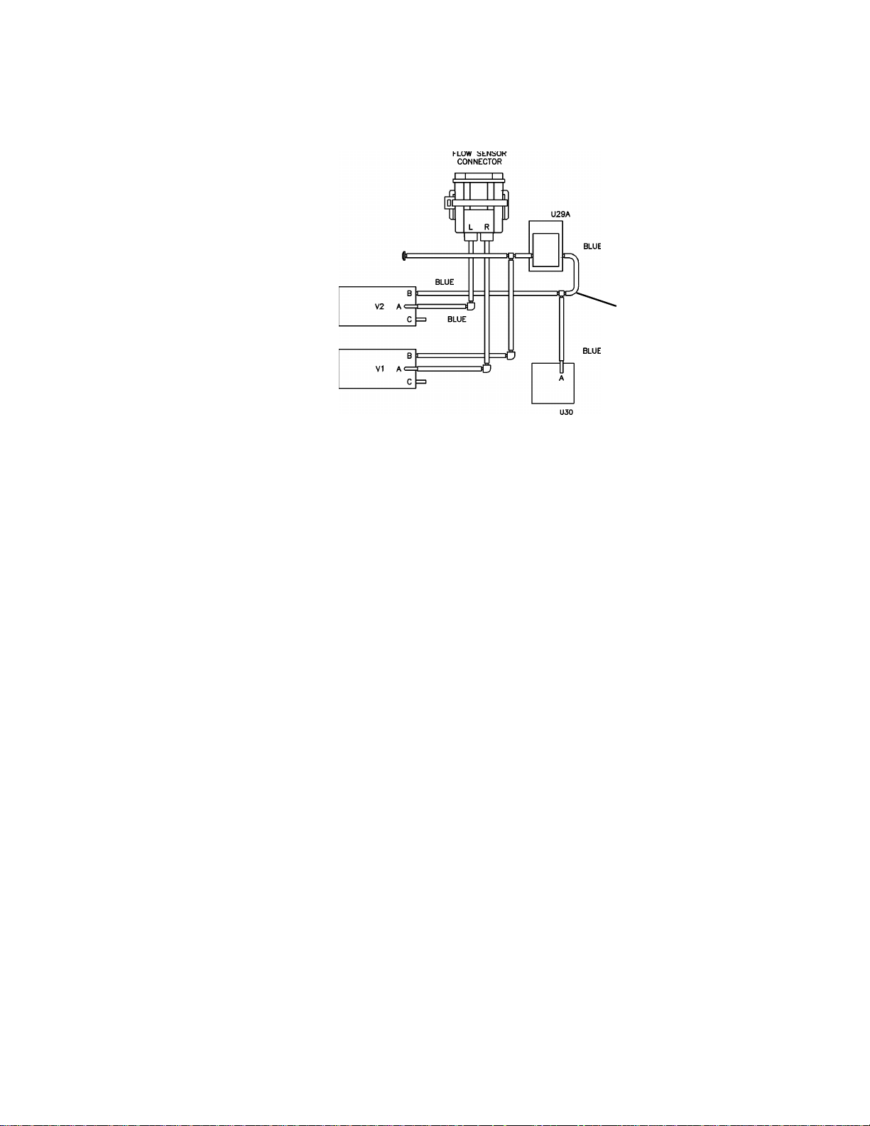
3.1.11 Flow Zeroing
Reference p age 3 of the 2740-0 3 schematic. The zero process begin s when the CPU brings the
VL V_CNTL li ne high, this biases Q3A on ener gizing v alv es V1 and V2. This disc onnects the diff erential
pressure transducer U29 (via V1 and V2) and the absolute pressure transducer U30 (via V2) from the
8
Model 101 Service
Manual Rev. 01
Page 17
Main Board
Section 3
patient airway, and opens all pressur e transducer ports to atmosphere. Diod es D16 and D17 ar e for
protection against back EMF from the valves coils.
AIRWAY PRESSURE
TRANSDUCER
VALVE 2
VALVE 1
PNEUMATIC TUBING
BAROMETRIC PRESSURE
TRANSDUCER
The pressure t ransducer s are “zeroed” by adj usting th e amplif ied and condit ioned pres sure output signals
so that each reading reads approxim ately mid-scal e (512 coun ts) using a s uccessive approxim ation
algorithm. With a reference v oltag e of 5.0 Volts, e ach count retu rne d by the 10-bit ADC is equa l to 4.8 83
mV. Centering the no flow (ambient) signal to the ADC's mid-scale allows the sensor to report both
positi ve and negati v e airw ay pressu res. U8 , a Digit al to A nalog Con ver ter (DA C) provid es the adjustmen t
under microprocessor control. The DAC maintains each adjustment voltage obtained during the zeroing
process until a new zero cycle is initiated.
The patient ai rway pressure t ran sduc er is "zeroed" fir st by adjusting the UB_DAC_A output of the DAC
until the Airway Pressure signal reads mid-scale. The barometric (ambient) pressure as sensed by the
processor is recorded after the airway pressure zero is completed. Next the flow channels are zeroed. A
non-inverting summing amplifier U6A combines two of the DAC's outputs and a constant voltage from
AVCC equal to the mid-scale of the ADC. The output voltage produced by the summer is fed into U14,
a monolithic instrumentation amplifier, which takes the differential output of the pressure transducer,
U29, and adds an of fset equal to the re feren ce v oltag e input . D A C output s UB_D A C_ A and UB_D A C _B
serve to provide the flow channels with a fine and a course adjustment. The result from each channel is
stored in SRAM and used as an offset in the flow calculations. Valves V1 and V2 are then de-energized,
reconnecting the pressure transducers with the patient airway.
Rev. 01
3.1.12 Flow Circuitry
Reference page 6 of the 2740-03 schematic. Differential Pressure Transducer, U29, is a silicon-based,
piezoresistive bridge with four active elements. When pressure is applied between transducer ports P1
and P2, a di f feren tial outpu t v olta ge prop orti onal t o the appli ed pr ess ure is pro duced. The ful l-sc ale i nput
pressure range for the transducer is 0 to 4 inches of water (P1>P2) . By sett i ng the 0 differenti al pres sur e
(no-flow) point to mid-scale (during the zeroing process described earlier), negative pressure readings
(P2>P1) are also available. The transducer is temperature compensated at 25 degrees Celsius and
designed to be driven by a constant current source (U6B).
In the no rmal system operating mode, al l valves are de -energized . Transducer p orts P1 and P2 are
connected to the patient airway. As air flows through the flow sensor, a pressure difference between P1
and P2 is created. This signal is dependent on both the magnitude and the direction on the air flow. The
greater the flo w vol ume, the lar ger the press ure dif f erenc e creat ed betw een the tw o trans duce r ports . The
transducer senses an inspired flow as a positive pressure difference (P1>P2), while an expiratory flow is
Model 101 Service
Manual
9
Page 18

Section 3
Main Board
seen as a ne gative pressure (P2>P1) . With a source vo lt age of approximately 5.0V, the s ensor transform s
this pressure difference into an electrical signal with a nominal absolute magnitude of 50 mV Full-scale
Output. This signal is conditioned and amplified by U14, which is a monolithic Instrumentation
Amplifie r (IA) . The flo w IA U14 als o of fset s th e signa l to the mid-rang e of the ADC obt ained du ring t he
zeroing p rocess. A positive p ressure difference (inspira tory flow) c reates a signal a bove the offs et
(approximately 1.25 to 2.5V). A negative pressure difference (expiratory flow) becomes a 1.25 to 0V
signal. The nom inal ga in of U14 i s set by f ix ed res istor R59 and va riabl e res istor VR1. T he o utput for t he
transducer is adjusted using VR1 and a known pressure input as a calibration reference. With an input
differential pressure of 10 inH
O, the gain of the amplifier is set to give an ADC count of 3498.
2
The signal out of the flow U14 is ta ken through a two-pole low pass filter U7B with a 31Hz cuto ff
frequency to remove unwanted high frequency electronic noise before it is passed on to the four gain
stages (U4 and U5). The four flow differential gain amplifiers provide signal gains of 1 (ACH_0), 10
(ACH_1) , 100 (A CH_2) a nd 1000 (ACH_3). The gain of 1 amplifier is used to b uf fer the fl o w sign al and
provide sign al conditionin g consiste nt with the ot her channe ls. The x10 , x100 and x10 00 chann els
amplify the flow signal according to the following equation:
V
out
= (V
where A
R
R
-Vrefo/2)(Av) + (Vrefo/2)
flow
is the amplifier gain, Rfb/Rv (1, 10, 100 or 1000)
v
is the feedback resistor (R51,R58, R68, R78)
fb
is the reference resistor (R131,R61, R73, R82)
v
The circuit is designed to amplify the difference between the flow signal into each gain stage and the
reference voltage so the zero point of each stage remains at mid-scale.
The output from each gain stage appears at the microprocessor for conversion into digital information.
An alternate pressure transducer, U29A may be installed in place of U29. The principal of operation is
the same a s d esc ri be d above wi th th e ex ce pti on th at it ’s full scale pressure input range is 0 to 10 inches
of water and it is excited by a constant 5.0 volt (AVCC) reference.
3.1.13 Barometric and Airway Pressure
Refer to page 7 of the 2740-03 schematic. U30 is a piezoresistive differential pressure transducer with
port P2 held at a vacuum (0 psi). It measures the absolute pressure difference at port P1 relative to the
vacuum at port P2. The transducer is calibrated for a full scale output of 0 to 30 psi, has internal
temperature com pensati on and is desig ned to be dri ven by a con stant cur rent source. Resi stor R99 is us ed
to set the current through the sensing bridge by amplifier U7A. Instrumen tation amplifier (IA) U23
conditions thi s sign al to corr espond t o the cur rent ba ro metric pressu re , which is set by adj usti ng VR2 for
span and VR3 for of fset. The nomina l gain of thi s amplif ier is 68.75. The out put signal from U23 appears
as an input to both the 10-bit ADC and a second IA, U24. U24 provides gain adjustment via VR4 and
offsets the output signal from the barometric amplifier to mid-scale during the zeroing state. This is
handled by the AW_DAC line fro m U2 A (pa ge 5 of the 2740-0 3 sc hem a ti c) , the output is then fed to the
low pass filter circuit of U12B. The nominal gain of the airway pressure amplifier is 2.1. This signal
connects t o the P1 ( proxi mal to t he p atien t) si de of t he dif f eren tia l pres sure t ransdu cer dur ing m onito ring
and provides patient airway pressure sensing (AWPRESS).
10
Model 101 Service
Manual Rev. 01
Page 19

Interface Board
Section 3
3.2 Interface Board
3.2.1 Key panel Interface
Refer to page 1 on 2741-03 schemat ic. The ke y panel ke ys are moni tored by the system thro ugh latch U4.
When any key is depressed the associated pull-up resistor (R9-R13) is brought low and the appropriate
line will appear as a low on the PD0-PD7 line. The latch is read by U22 from the main board (lines PD0PD7) when the 0xF800 line is asserted.
3.2.2 Display interface
Refer to page 1 on 2741-03 schematic. Communication to the display is handled by latches U1 and U2,
these in turn are controlled by U22 on the main board. U1 i s ena bl ed by t he oxF806 line and han dle s the
display data lines DS0-DS7. The remaining control lines are handled through U2 and the 0xF807 line.
3.2.3 LED control
Refer to page 1 on 2741-03 schematic. The LEDs on the front panel display are controlled by latch U2
and the 0xF807 li ne. LEDs D1 an d D2 are bico lor LED s that are con tro lled b y two li nes each . D3and D4
are unicolor LEDs.
3.2.4 Power Supplies
Refer to page 2 on 2741- 03 sch ematic . The VSW DC suppl y from the main b oard i s re gula ted t o a + 5 v olt
supply by U3, a VALVE_SUPPLY supply by U7 and ±12 volt supplies by U5 and U6. U7 is used as a
separate5 volt regulator for the main board valves. The other supplies are connected to the main board
through J2.
Rev. 01
Model 101 Service
Manual
11
Page 20

Section 3
Interface Board
12
Model 101 Service
Manual Rev. 01
Page 21

Section 4
Functional Tests
4.1 Equipment Required
1. Adult Flow Sensor Cat. No. 6717-01
2. Neonatal Flow Sensor Cat. No. 6718-01
3. Battery Case Cat. No. 6862-00
4. AA 1.5 VDC Alkaline Batteries (Qty 7) Cat. No. 400038
(Panas onic AM3X or equivalent)
4.2 Procedure
1. Inspect the unit for cosmetic defects, verify no damage.
2. Install the Battery Case (loaded with seven good AA Alkaline batteries).
3. Press the
4. Connect the 6717-01 Adult Flow sensor to the unit.
5. Breathe into the flow sensor.
6. Press the
7. Remove the flow sensor from the unit. Verify the unit displays “NO SENSOR
DETECTED INSERT FLOW SENSOR”
8. Connect the 6718-01 Neonatal Flow Sensor to the unit under test. Verify a “NEW
SENSOR D ETECTED TY PE: Neonata l” is temporar ily displayed. Verify the
LED illuminates.
9. Remove the flow sensor.
10. Press the lamp key and verify that the backlite shuts off.
POWER
GRAPH
key to power up the unit.
key and ve rify that all of the Graph screen is functioning prope rly;
VOLUME GRAPH
• Automatically scaled.
• Breath-by-breath reporting.
NEO
11. Press the lamp key again and verify the backlite turns back on.
Rev. 01
Model 101 Service
Manual
13
Page 22

Section 4
Procedure
12. Press and hold the lamp key and verify that the contrast is adjustable. Set the
contrast to a desirable level.
13. Power the unit down by pre ssing the
14. Press and
engineering menu.
15. Verify the AC LED is off and the battery LED is on.
16. Press the
17. Press the
the displayed LED test is ON.
18. Press the
return to normal operating mode.
19. Power the unit down by pre ssing the
20. The Functional Test Procedure is complete.
hold
GRAPH
DATA
GRAPH
DATA
the
(next) key until the arrow is beside “TEST LEDs”.
(select) k ey to s tart the LED test. Verify the LED that corresponds to
LED Test
Neo Neo Green
LED TEST Battery Red
Battery OK Battery Green
Low Battery Batt e ry Yellow
(next) k e y unt il th e arro w is next to “EXIT”. Press
key, then press t he
POWER
LED On LED Color
POWER
key.
POWER
key.
key to powe r up the unit in the
DATA
(select) to
14
Model 101 Service
Manual Rev. 01
Page 23

Section 5
Accuracy Tests
5.1 Equipment Required
1. Calibrated Barometer
2. Adult Flow Sensor, PN: 6717-01
3. Neonatal Flow Sensor, PN: 6718-01
4. 500 cc Calibration Syringe, Hans Rudolph 5550 or equivalent
5. 10 cc Calibration Syringe , Hans Rudol ph, Model 5520 or equivalent PN: 550032
6. Flow Leak Test Adapter, PN: 6935-48
7. Common Mode Test Adapter, PN: 6937-48
8. Pressure Source, Penwalt Pneumatic Cali brator, Model 65- 120 or equi valent
9. Battery Case Cat. No. 6862-00
10. AA 1.5 VDC Alkaline Batteries (Qty 7) Cat. No. 400038
(Panas onic AM3X or equivalent)
5.2 Procedure
1. Install a Battery Case (Cat No 6862-00) with seven fully charged AA batteries (Cat
No 400038) in the Model 101.
DATA
2. Press and
engineering menu.
3. Verify the AC LED is off and the battery LED is on.
4. Press the
DATA
key (select).
5. Read the current barometric pressure from the calibrated barometer. Verify Pbar
equals the current barometric pressure ± 2.
6. Connect the 6935-48 Flow Leak Test Adapter to the unit.
7. With the stop cock on the FLow Leak Test Adapter open, set the airway pressure
(Paw) to 100 - 110 cmH
8. Close the stop cock.
9. Verify the airway pressure (Paw) remains the same for at least 30 seconds.
10. Disconnect the Flow Leak Test Adapter .
the
hold
GRAPH
key (nex t) unti l the ar row is beside “CALIBRATION” then press t he
key, then press t he
O.
2
POWER
key to powe r up the unit in the
Rev. 01
Model 101 Service
Manual
15
Page 24

Section 5
Procedure
11. Connect the 6937-48 Common Mode Test Adapter to the unit.
12. Using the pressure source , apply 20 cmH
O to the Common Mode Test Adapter.
2
13. Verify a Paw value of 20.0 ± 2.0.
14. Increase the pressure sour ce to 80 cmH
O.
2
15. Verify a Paw of 80.0 ± 2.0.
16. Press the
POWER
key (EXIT) to e xit t he Calibr ation scr een. Press t he
key until the arrow is beside “EXIT”, then press the
DATA
(select) key to exit.
GRAPH
(next)
17. Connect the 6717-01 Adult Flow Sensor to the 500cc Calibration Syringe, then
connect to the Model 101.
18. Press the
DATA
key to display the Flow/Volume screen (repeated key depressions
may be required).
19. Pump the Calibration Syringe at approximately 20 cycles per minute (one stroke
every 3 seconds), use a smooth and steady action when pumping the syringe.
20. Verify VTi and VTe read 500ml ± 25ml.
21. Press the
GRAPH
key. Verify the Volume screen is displayed (repeated key
depressions may be required).
22. Verify a Vt of 500ml ± 25ml with a volume waveform present.
23. Remove the Adult Flow Sensor. Verify the unit displays “NO SENSOR DETECTED
INSERT FLOW SENSOR”
24. Install the 6718-01 Neonatal Flow Sensor. Verify a “NEW SENSOR DETECTED
TYPE: Neonatal” is temporarily displayed. Verify the
NEO
LED illuminates and the
Volume waveform screen is then displayed.
25. Connect the Neonatal Flow Sensor to the 10cc Calibration Syringe.
26. Pump the syringe at approximately 40 cycles per minute (one stroke every one and
one-half second).
27. Press the
DATA
key to display the Flow/Volume screen (repeated key depressions
may be required).
28. Verify a VTi and VTe of 10ml ±2 ml.
29. Remove the flow sensor.
30. Power the unit down by pre ssing the
POWER
key.
31. The Accuracy Test Procedure is complete.
16
Model 101 Service
Manual Rev. 01
Page 25

Section 6
g
g
g
g
g
g
6.1 Equipment Required
1. Digital Multimeter, Fluke model 8840A or equivalent
2. Oscilloscope, Tektronix model 2236 or equivalent
3. Pneumatic Calibrator, Pennwalt Model 65-120 or equivalent
4. Calibrated Barometer
5. Flow Leak Test Adapter, PN: 6935-48
6. Differential Test Adapter, PN: 6936-48
7. Common Mode Test Adapter, PN: 6937-48
8. Adult Flow Sensor, PN: 6717-01
9. Neonatal Flow Sensor, PN: 6718-01
Electrical Tests
10. 500cc Calibration Syrin
11. 10cc Calibration Syrin
e, Hans Rudolph Model 5550 or equivalent
e, Hans Rudolph Model 5520 or equivalent, PN: 550032
6.2 Procedure
6.2.1 Power Supplies
1. With the monitor off, remove the bottom cover to expose the internal circuit boards.
Refer to "Disassembling the Monitor" on page 25.
2. Measure the followin
nal Name Location Voltage Tolerance
Si
BVDD TP15 5.10 Vdc ± 100 mV
THERM TP16 2.25 Vdc ± 50 mV
3. Press the
4. Measure the followin
POWER
Si
nal Name Side Location Voltage Tolerance
voltages. Use TP4 as ground reference.
key on the monitor.
voltages. Use TP2 as ground reference.
F5V Front IC19 pin 28 5.10 Vdc ± 100 mV
Rev. 01
Model 101 Service
Manual
17
Page 26

Section 6
g
g
g
g
g
g
g
g
g
g
Procedure
TP_POS_12V Front IC16 pin 8 12.0 Vdc +100 mV
- 300mv
TP_NEG_12V Front IC16 pin 4 -11.5 Vdc ± 500 mV
TP_AVCC Front TP1 5.00 Vdc ± 25 mV
TP_AVCC_2 Front TP2 2.50 Vdc ± 25 mV
TP_1.47V Front TP3 1.47 Vdc ± 25 mV
NEG_AVCC_2 Back IC24 pin 4 2. 50 Vdc ± 25 mV
5. Measure the voltage at IC7 pin 3 on the 2741-01 board. Verify 5.00 Vdc ± 100 mV.
6. Monitor IC11 pin 8. Verify a volta
e < 4.1 Vdc.
7. Monitor IC11 pin 10. V erify 0 VDC.
8. Monitor IC11 pin 14. Verify a switchin
pulse with a frequency of approximately 85
KHZ.
Note: The frequency, pulse width, and period will chan
e status.
char
9. Usin
a clip lead short TP15 to TP16. Verify the switching frequency at IC11 pin 14
es from approximately 85 KHZ to < 50 HZ. Verify IC1 pin 10 goes high.
chan
e depending on the battery
6.2.2 Airway Pressure Calibration
10. Press the
11. Press and
engineering menu.
12. Press the
the display. Press the
Note:
They are (in order):
PAW_ADU The A/D counts reading for the airway pressure channel.
PAW The airway pressure in cmH
1. Press the
POWER
hold
GRAPH
key to turn the u ni t off.
the
DATA
key, then press t he
POWER
key to powe r up the unit in the
(next) key until th e select ion arrow i s point in
(select) key to enter the Calibration screen.
DATA
The second line of the calibration screen (Paw) has 2 parameters.
O.
2
GRAPH
(ZERO) ke y.
to “CALIBRATE” on
18
Model 101 Service
2. Connect the Common Mode Test Adapter t o the uni t and to t he Pennwalt. Adj ust t he
Pennwalt to 90 cmH
Note: The pressure settin
O.
2
s for the Airway Pressure adjustment is stated in cmH2O.
Use the Inner scale on the Pennwalt when setting the pressure to cmH2O.
3. Adjust VR4 until the PAW readin
4. Press the
GRAPH
(ZERO) ke y.
5. Repeat steps 3 and 4 until the PAW readin
matches the Pennwalt reading of 90 cmH2O.
is within ± 0.5 cmH2O as read from the
Pennwalt meter.
6. Disconnect the Common Mode Test Adapter.
Manual Rev. 01
Page 27

Barometric Pressure Calibration
g
g
g
6.2.3 Differential Pressure Calibration
The calibration scr een displays 2 c olumns of v alues for the x1, x10, x100, and x 1000 chan-
Note:
nels of the differenti al pr essure sensor. They are (in order):
ACTUAL_CNTS The actual A/D counts f or the respective channel.
DIFF_CNTS
1. Connect the 6936-48 Differential Test Adapter to the 2740-01 board.
Section 6
The diffe rence between the actual A/D c ounts and the A/D
counts at the zero point.
2. Press the
3. Connect the Pennwalt to the positive pressure port (blue tube).
4. Adjust the Pennwalt to 11 cmH
5. Adjust VR1 until the x1 channels DIFF_CNTS reads 887 counts.
6. Press the
7. Repeat steps 5 and 6 until the x1 channels DIFF_CNTS is 887 counts ± 2 counts.
8. Switch the Pennwalt’s output from the positive port to the ne
of the Differenti al t e st fixture.
9. Verify the x1 channel reads -887 counts ± 25.
10. Disconnect the Differ ential Test Adapter.
GRAPH
GRAPH
(ZERO) ke y.
(ZERO) ke y.
O.
2
ative port (clear tube)
6.3 Barometric Pressure Calibra tion
Perform the following only if the barometric pressur e r eading of the monitor does not mat ch the
currrent baromet ric pres sure as recorde d f rom a cal i brated baro meter. This procedure requires
adjustments for offsets within the electronic circuitry and mu st be performed accurately and
carefully.
1. Connect the 6937-48 Common Mode Test Adapter to the monitor.
Rev. 01
2. Press and
engineering menu.
3. Press the
the display. Press the
4.
Note:
They are (in order):
BARO_ADU The A/D counts reading for the barometric pressure channel
ADDED_PRESSURE
BARO_PRESSURE
5. Adjust VR3 so that the BARO_ADU readin
hold
GRAPH
The top line of the calibration screen (Pbar) has 3 parameters displaye d.
DATA
the
(next) key until th e select ion arrow i s point in
key, then press t he
(select) key to enter the Calibration screen.
DATA
The applied gage pressure (mmHg) to the unit. This parameter
must be read after a ZER O. Chang ing the offs et or span wi ll make
this number meaningless until the next zero.
The TOTAL pressure (mmHg). Barometric plus added
pressure. With no pressure applied, this will equal the
barometric pressure.
POWER
is about 1000 counts.
key to powe r up the unit in the
to “CALIBRATE” on
Model 101 Service
Manual
19
Page 28

Section 6
g
g
g
g
g
g
g
g
g
g
Barometric Pressure Calibration
6. Press the
7. Connect the Pennwalt pneumatic calibrator to the Common Mode Test Adapter.
8. Adjust the Pennwalt for an output pressure of 50 mmH
Note: The pressure settin
mmHg not cmH2O. Use the outer scale on the Pennwalt when setting the pressure
to mmH
9. Adjust VR2 until the ADDED_PRESSURE readin
VR3 if BARO_ADU becomes
10. Press the
11. Repeat steps 9 and 10 until the ADDED_PRESSURE is within ± 2 mmH
Pennwalt setting.
12. Adjust the Pennwalt for an output pre ssure of 100 mmH
13. Adjust VR2 until the ADDED_PRESSURE readin
14. Press the
15. Repeat steps 13 and 14 until the ADDED_PRESSURE is within ± 1 mmH
Pennwalt settin
16. Disconnect the Pennwalt from the Common Mode Test Adapter.
17. Press the
18. Obtain the current Barometric Pressure from the calibrated Barometer.
GRAPH
.
GRAPH
GRAPH
GRAPH
(ZERO) ke y.
.
s for the Barometric Pressure adjustments are stated in
is 50 (you may need to readjust
reater than 3500 counts).
(ZERO) ke y.
.
is 100.
(ZERO) ke y.
.
(ZERO) ke y.
of the
of the
19. Adjust VR3 until the BARO_PRESSURE value matches the Barometric pressure
obtained from the calibrated Baromet er.
20. Press the
21. Repeat steps 19 and 20 as needed.
GRAPH
(ZERO) ke y.
20
Model 101 Service
Manual Rev. 01
Page 29

Section 7
7.1 General
This section presents recommended maintenance schedules for the Model 101 and information on
general maintenance, such as battery replacement, disassembly and assembly instructions, and system
software updates.
7.2 Maintenance Schedules
The electronic circuits within the Model 101 do not require scheduled calibration or service. However,
in order to maximize battery life, the monitor’s intern al ba ttery s hould be tes ted mo nthly. Novametr ix
recommends the following maintenance schedules.
• Cleaning and Sterilization:
Perform as required. See Cleaning and Sterilization on page 22.
• Battery and AC Operation:
Contains information on use of disposabl e al kal i ne and rechargeable ba tt er ie s. See Battery and AC
Operat ion on page 22.
• Functional Tests:
The test verifi es overall function al integr ity of the moni tor and sensor. See Func tional Tes ts on page
13.
• Accuracy Tests:
The test verifies the calibrati on accuracy of the monit or using specifi ed test apparatu s. See Accuracy
Tests on page 15.
• Electric al T est s:
These tests contain information on testing the electronic circuits within the Model 101 and should
only be perf ormed if the monito r fails to pass t he Func ti onal and or Accurac y Tes ts . Only qualified
service personnel should attempt to perform the Electrical Tests. See Electrical Tests on page 17.
Maintenance
*
*.
At the customer’s request, Novametrix will provide repair and calibration services under terms of a Service Contract. Contact the
Novametrix Service Department for contract details.
Rev. 01
Model 101 Service
Manual
21
Page 30

Section 7
Cleaning and Sterilization
7.3 Cleaning and Ster ili za tio n
Follo w the c leani ng and s teri liza tion inst ruct ion s liste d be lo w to cl ean and/ or st eril ize t he mon itor and it s
accessories.
CAUTION
The airway adapter is designed for single patient use. Sterilizing may affect system performance.
• Turn the monitor off and disconnect from any other devices before cleaning.
• Do not immerse the monitor.
• Do not attempt to sterilize the monitor.
• The monitor can be cleaned and disinfected with solutions such as a 70% isopropyl alcohol, 2%
glutheralhyd e, or 10% ble ach solut ion. Then wip e down with a water-dam pened cl ean clot h to rins e.
Dry before use.
• Treat Series 3 Flow Sensors in accordance with hospital protocol for single-patient use items.
7.4 Battery and AC Operation
The Model 101 ca n be powered from seven “AA” disposable alkaline batteri es or a rechar geab le batte ry.
Battery capaci ty is sho wn in the ch art belo w . T ime s may be reduced in colder tem peratur es or with po wer
cycling; operation with the backlight off may slightly increase these times. Any batteries used with the
6862-00 case cannot be charged, it is for use with disposable type batteries only.
Standard
AA alkaline batteries
(7 ea. - disposable)
Power Source
Capacity, continuous 8 hours 12 hours
Recharge Time n/a 4.5 hours
Catalog Number
AA Alkaline Batteries.
batteries (Panasonic AM3X or equivalent) into the Battery Case (Cat. No. 6862-00) following the
polarity markings on the case.
T o power Model 101 from AA alkaline bat teries, inse rt sev en disposable alkal ine
400038 (battery)
6862-00 (case)
Optional
Rechargeable battery,
(NiMH 7.2 vdc)
400043
WARNING:
Do not recharge or incinerate alkaline batteries. Attempting to do so may
!
cause the batteries to leak or explode.
22
Model 101 Service
Rechargeable Battery.
battery. If a rechargeable battery has not been used for three months or more, recharge it before use.
Model 101 can operate from the optional NiMH (or equivalent) rechargeable
WARNING:
Battery can explode, leak or catch on fire if heated or exposed to fire or high
!
temperatures.
Manual Rev. 01
Page 31

Battery and AC Operation
• New batteries, or batteries stored for extended periods of time may need to be
• With a new battery, or a battery that has not been used for 30 days, charge the
• Ref er to inst ructions packaged wi th rechargeab l e battery for complete operati ng
Additi onal Batt ery Information.
• Dispose of batteries in accordance with local laws.
• Do not mix battery types (e.g. disposable and rechargeable AA batteries).
• Model 101 may not power up if the batteries are nearly depleted.
7.4.1 Battery Installation
To install or remove the battery, grasp the finger grips on each end of the Mo del 101 battery cover.
Squeeze together and pull so that the hinged cover opens. The battery is keyed and can be installed in
only one orientation (see illustration inside battery compartment). The contacts should go in first and be
located toward the to p left of the monitor. Close the battery cover before operating the monitor.
Section 7
NOTE:
fully charged and discharged up to five (5) times before performing at full
capacity.
battery for 24 hours prior to use.
instructions.
Connect only Novamet rix approved devices
Hinged Battery Compartment Cover
Finger Grips
Swing battery
cover open
7.4.2 External Battery Charger
An optional external charger for the NiMH rechareable battery pack is available. The external charger
allows the battery to be recharged outside of the Model 101 monitor.
• The external charger is for use with the rechargeable NiMH battery only.
• In a non-patient area, connect the external charger to an AC source. Remove the battery from the
Model 101 and insert it into the external charger. The battery will be fully charged in approximately
4.5 hours.
• Refer to the instructions supplied with the charger for additional information.
WARNING:
The external battery charger should NOT be operated near or in close
!
proximity to patients and/or other medical equipment in operation.
Rev. 01
Model 101 Service
Manual
23
Page 32

Section 7
Battery and AC Operation
7.4.3 Features Connector
Located on t he enclo sure rea r is a six pin modu lar cont act which provid es a po wer i nput for unit ope ration
and battery ch ar ging when connect ed to N ov am etrix acc ess orie s. This co nnector meets t he pati ent saf ety
requirements of the following agencies: IEC 601-1, UL544, and TUV.
24
Model 101 Service
Manual Rev. 01
Page 33

Assembly Exchanges
7.5 Assembly Exchanges
7.5.1 Disassembling the Monitor
1. Ensure that the monitor is OFF. Remove the battery pack.
2. Turn the monitor upside down and remove the four cover screws from the bottom
Section 7
The disassembl y inst ruct ions bel o w are intend ed as a gui de to ena ble com ponent exc hanges i f nece ssa ry.
There are no user serviceable parts inside. Disassembly should be performed by qualified service
personnel only.
CAUTION
The Model 101 contains static sensit ive devices. Be sure to follow proper grounding
procedures when handling the internal components to avoid damage from static disc harge.
cover.
cover screws
3. Carefully lift the r ear cover from the monitor. The separate assemb l ies of the monito r
can now be remov ed.
4. Lift the Main Board a nd disconnect ribbon cab le f rom the Interf a ce Board b y graspi ng
the connector (not the cable) and gently rocking from side to side to loosen. Be
careful not to bend any pi ns when pull ing the connector off of the header strips.
ribbon cable
main board
Rev. 01
side view
Model 101 Service
Manual
25
Page 34

Section 7
Assembly Exchanges
5. Remove the Main Board.
6. The Interfac e Board and batt ery connector can now be accessed.
7. To disconnect ribbon cable J3, grasp the edge of the ZIF (zero insertion force)
connector with one forefinger on either side. Pull gently
mechanism. Slide the ribbon cable out.
ZIF connector
ribbon cable
sideways
to release the
8. Remove four screws from the Interface Board. Disconnect the screw on the battery
connector (black and red wires).
inerface board screws
J1 header
9. Slide the battery connector out of the brac ket and remo ve the inter face bo ard, rocking
gently to releas e the header strip J1 which c onnects through th e Interf ace Board from
the Display Board below.
battery connector screw
battery connector
26
Model 101 Service
Manual Rev. 01
Page 35

Assembly Exchanges
10. Remove 4 screws holding the Display Board in place. Do not bend the tabs on the
Section 7
board, the LCD display can not be removed from the board. Be sure not to lose the
plastic bezel located in between the LCD display and the display window.
display board
screws
ribbon cable
7.5.2 Reassembling the monitor
1. Check the inside of the display window and the LCD display for dirt/finger prints,
clean if nece ssary. Replace the plastic be zel around the displ ay window. Set the
Display Board i n place and secure with 4 screws.
2. Place the battery connector (red and black wires) into the bracket and push in.
Secure in place with 1 screw.
3. Place the Interface Board in the case, taking care to align the pins at header strip J1
underneath—line the LEDs up with the openi ngs in the ca se, thi s will giv e y ou a point
of reference. When you are sure the pins are lined up with the holes, gently push
down, do not f orce . Place the stra in rel ief sec tion on t he sensor cab le i nto the eg ress
slot, push down to lock in.
4. Secure the Interface Board with 4 screws.
5. Slide ribbon cable J3 into the ZIF locking connector, pushing gently to be sure that
the cable is as fa r into the lock ing mechanism as possibl e. Push the connector cl osed
to lock in the ribbon cable. Pull lightly on the ribbon cable to ensure that it is secure.
6. Replace ribbon cable from the Main Board to the Interface Board and align the main
board with the standoffs.
7. Ensure the battery gasket is set in place, refer to the assembly print 6800-01 (page
3) for placement . Pla ce the back cover on the monitor. Secure with 4 screws.
8. Opened hinged cover and replace the rechargeable battery or battery pack. Battery
is keyed to fit in only one direction. When the monit or is powered it will default to the
factory default settings.
Rev. 01
Model 101 Service
Manual
27
Page 36

Section 7
Assembly Exchanges
28
Model 101 Service
Manual Rev. 01
Page 37

Section 8
g
g
g
g
g
Cat. No. Description
Accessories
Monitor (En
6800-00
6800-23
6800-90
420037
420038
420039
Flow Sensors
6717-00 Series 3, Pediatric/Adult Flow Sensor. 10/Box
6718-00 Series 3, Neonatal Flow Sensor. 10/Box
6720-00 Series 3, Neonatal Combined CO
Power Options
6862-00 Battery Case for AA Batteries (batteries not included)
400038 Alkaline Battery, 1.5 vdc, AA Size
lish language)
✔ Handheld Respiratory Mechanics Monitor, Model 101
VENT
User's Manual
Service Manual
✔ Quick Guide Inservice Video
VENT
VHS video tape, NTSC format (U.S.A.)
VHS video tape, PAL format
VHS video tape, SECAM format
(Panasonic AM3X or equivalent)
/Flow Sensor. 10/Box
2
400043 Rechar
(Duracell® DR30 or equivalent)
400049 External Battery Char
(power line cord not included)
600026 Power Line Cord, 120 vac, (U.S.A.) for External Battery Char
Miscellaneous
140084 Pole/Shelf Mount Kit
315107 Carryin
Rev. 01
eable Battery, NiMH, 7.2V, 2.4AH,
er (DR30), Universal Voltage, NiMH
Case
Model 101 Service
er
Manual
27
Page 38

Section 8
[This page intentionally blank.]
28
Model 101 Service
Manual Rev. 01
Page 39

Section 9
9.1 6800-00 Final Assembly, Model 101
LINE PART NO REV QPA DESCRIPTION
0001 6800-01 02 1 MAIN ASSY, MODEL 101 - VENTCHECK
0002 6800-04 XX 0 TEST PROCEDURE, SYSTEM, MODEL 101 - VENTCHECK
0003 6800-09 P0 0 OVERALL WIRING DIAGRAM, MODEL 101 - VENTC H EC K
0004 6800-23 02 1 USERS MANUAL, MODE L 101 - VENTCHECK
0005 6800-33 XX 0 ASSY PROCEDURE, SHIPPING INSTRUCTIONS, MODEL 101
0006 6800-40 00 0 DESIGN DOCUMENTATION, MODE L 101 - VENTCHECK
0007 6800-43 XX 0 DATA SHEET, MODEL 101 - VENTCHECK
0008 6800-75 02 0 DEVICE MASTER RECORD, MODEL 101 - VENTCHECK
0009 6835-32 00 1 LABEL, PATIENT ISOLATION, MODEL 101
0010 6874-32 00 1 LABEL, SERIAL NO. & BATTERY ALIGNMENT
0011 6877-32 00 1 QUICK GUIDE LABEL, BOTTOM COVER, MODEL 101
0012 6886-13 00 1 CARTON, SHIPPING, HAND HELD MONITOR
0013 6920-13 00 1 SHIPPING CARTON, ACCESSORIES, HAND HELD MONITOR
0014 6965-32 00 1 REGULATORY LABEL, UL MARK FOR USA & CANADA
0015 9026-32 01 1 LABEL, "MANUFACTURED IN USA"
0019 240059 0 SCREW COVER, BLK, PVC, .25DIA X .06T, ACRYLIC
0020 315033 0 POUCH, PLASTIC, ZIP LOCK, 4" X 6", 2 MIL THICK
Parts Lists
9.2 6800-01 Main Assembly, Model 101
LINE PART NO REV QPA DESCRIPTION
0001 2740-01 01 1 MAIN BOARD ASSY, MODEL 101 - VENTCHEC K
0002 2741-01 00 1 INTERFACE BOARD ASSY, MODEL 101 - VENTCHECK
0003 6680-13 01 1 BOTTOM COVER W HOLE AND SHIELDING, HAND HELD
0004 6685-16 00 1 BATTERY DOOR, HAND HELD ENCLOSURE
0005 6773-10 00 1 SHIELD, MYLAR, BOTTOM COVER, MODEL 101
0006 6823-10 01 1 FILLER, KEYPANEL
0007 6824-27 01 1 MEMBRANE KEYPANEL, MODEL 101 - VENTCHECK
0008 6838-10 01 1 GASKET, BATTERY DOOR
0009 6839-10 00 1 GASKET, BATTERY
0010 6855-13 00 1 TOP COVER WITH SHIELDING, MODEL 101
0012 161082 0 TAPE, UHMW POLYETHYLENE, .002 THK
0013 161102 0 ADHESIVE, RTV162, SILICONE, WHITE
0014 160044 0 ALCOHOL, ISOPROPYL, TECHNICAL GRADE
0015 281211 0 SCREW, 2-56 X 1/4L, SELF TAPPING, BINDING HEAD
0016 286223 0 SCREW, 6-32 X 3/8 IN. L, PAN HD, PHILLIPS, ST
0017 482605 1 LCD DISPLAY, W LED BACKLIGHT & CONN W GOLD PL
0018 600068 1 RIBBON CABLE, 40 PIN, RCPT TO RCPT, 3.5 IN. L
0019 600518 1 BATTERY INTERCONNECTION CABLE, 5 PIN, 2.3 IN.
Rev. 01
Model 101 Service
Manual
29
Page 40

Section 9
9.3 2740-01 01 Main Board Assy, Model 101
PART NO REV QPA DESCRIPTION
161102 0 ADHESIVE, RTV162, SILICONE, WHITE
2740-03 01 0 SCHEMATIC, MAIN BOARD, MODEL 101 - VEN T C HE C K
2740-04 XX 0 TEST PROCEDURE, MAIN BOARD, MODEL 101
2740-17 01 1 MAIN BOARD SUBASSY, MODEL 101 - VENTCHECK
487128 1 IC, DUXL01D, DIFF PRESSURE SNSR, 1 IN, H20, 4
608012 0 CABLE TIE, SELF -LKG, .094W X 8L, 1/16 TO 2" B
6837-10 01 1 GASKET, CONNECTOR CRADL E, MODEL 101
6961-01 01 1 FLOW CONNECTOR AND TUBING ASSY, 101
6962-07 12 1 PROGRAM, EPROM ASSY, SYSTEM, 101 - VENT C HECK
9.4 2740-17 01 Main Board Subassy, Model 101
PART NO REV QPA DESCRIPTION
130015 1 TRANSDUCER, AUDIO, 2400 HZ, 12V, 40MA, .5 DIA
154062 23 CAPACITOR, .01UF, 50V, 10%, X7R, SURFACE MOUNT
154072 59 CAPACITOR, .1UF, 50V, 10%, X7R, CER CHIP, S M
154078 1 CAPACITOR, 1000PF, 50VDC, 10%, NPO, MONO CERA
154079 7 CAPACITO R, 10UF, 25V, 10%, TANTAL UM, SURFACE
154080 8 CAPACIT OR, 47UF, 10VDC, 10%, TAN TALUM, SURFAC
154081 1 CAPACITOR, 100PF, 100V, 10%, NPO, MLTILYR CER
154082 2 CAPACITOR, 22PF, 100V, 10%, NPO , MLTILYR CERA
154093 2 CAPACIT OR, 68UF, 16VDC, 10%, TAN TALUM, SURF M
180022 3 INDUCTOR, 10UH, 10%, SURFACE MOUNT
180029 15 INDUCTOR, 50MHZ CUT-OFF FREQUENCY, SURFACE MO
180030 2 INDUCTOR-CAP, 4700PF, 50VDC, 2A, 3 TERM, SURF
180046 1 INDUCTOR, 18UH @ 2.5M HZ, +25% -15%, SURFACE
180047 4 INDUCTOR, 50 OHMS @ 100M HZ, 3A, 1206 STYLE,
210141 1 CONNECTOR, DC PWR JACK, SOLDER TERM, PC/PNL M
211415 1 CONNECTOR, 4 PIN, H EADER, .079 SP, R ANG, PC
213412 1 CONNECTOR, 40 PIN, HEADER, DIL, STR, .05 SP,
215073 1 SOCKET, PLCC, 32 PIN, .05 SP, LOW PROFILE, S
216029 0 TEST POINT, SPRING LOADED, 475 DEG C MAXIMUM
230027 1 CRYSTAL, 12.00 MHZ, .192 SP, HC-49/US STYLE,
250146 2 VALVE, SOLENOID, 5V, 0-30 PSIG, 10 PSID MAX,
2739-01 00 1 BAT TERY & COMM INTERFACE BOARD ASSY, MODEL 61
2740-02 01 1 FAB, MAIN BOARD, MODEL 101 - VENTCHECK
474127 1 RESISTOR, 511K OHM, 1/8W, 1%, SURFACE MOUNT
474136 1 1 RESISTOR, 1K OHM, 1/8W, 1%, SURFACE MOUN T
474137 3 RESISTOR, 1M OHM, 1/ 8W, 1%, SURFACE MOUNT
474138 30 RESISTOR, 100 OHM, 1/8W, 1%, SURFACE MOUNT
474141 2 RESISTOR, 249K OHM, 1/8W, 1% , SURFACE MOUNT
474152 2 RESISTOR, 3.01K OHM, 1/8W, 1%, SURFACE MOUNT
474157 3 RESISTOR, 511 OHM, 1/8W, 1%, SURFACE MOUNT
474161 1 RESISTOR, 5.9K OHM, 1/8W, 1%, SURFACE MOUNT
474165 26 RESISTOR, 10K OHM, 1/8 W, 1%, SURFACE MOUNT
474166 19 RESISTOR, 100K OHM, 1/ 8W, 1%, SURFACE MOUNT
474170 2 RESISTOR, 301K OHM, 1/8W, 1% , SURFACE MOUNT
474182 2 RESISTOR, 150K OHM, 1/8W, 1% , SURFACE MOUNT
474185 1 RESISTOR, 150 OHM, 1/8W, 1%, SURFACE MOUNT
30
Model 101 Service
Manual Rev. 01
Page 41

PART NO REV QPA DESCRIPTION
474186 1 RESISTOR, 15K OHM, 1/8W, 1%, SU R FACE MOUNT
474211 7 RESISTOR, 49.9K OHM, 1/8W, 1%, 1206 STYLE, S
474216 1 RESISTOR, 4.99K OHM, 1/8W, 1%, 1206 STYLE, SR
474220 7 RESISTOR, ZERO OHM, 1/4W, 5%, 1206 STYLE, SUR
474263 1 RESISTOR, 28K OHM, 1/8W, 1%, 1206 SIZE, SURF
474273 1 RESISTOR, 14.7K OHM, 1/8W, 1%, 1206 STYLE, SU
474274 8 RESISTOR, 20K OHM, 1/8W, 1%, 1206 STYLE, SURF
474275 2 RESISTOR, 1.5K OHM, 1/8W, 1% , 1206 STYLE, SUR
474277 1 RESISTOR, .15 OHM, 1/2W, 2010 STYLE, SURFACE
474278 1 RESISTOR, 237K OH M, 1/8W, 1%, 1206 STYLE, SUR
474279 1 RESISTOR, 562 OHM, 1/8W, 1%, 1206 STYLE, SURF
474280 1 RESISTOR, 243 OH MS, 1/8W, 1%, 1206 STYLE, SUR
474281 1 RESISTOR, 71.5K OHM, 1/8W, 1%, 1206 STYLE, SR
474282 1 RESISTOR, 4.64K OHM, 1/8W, 1%, 1206 STYLE, SR
474285 1 RESISTOR, 255 OHM, 1/8W, 1%, 1206 STYLE, SURF
474287 6 RESISTOR, 200K OH M, 1/8W, 1%, 1206 STYLE, SUR
474288 2 RESISTOR, 499 OHM, 1/8W, 1%, 1206 STYLE, SURF
474289 1 RESISTOR, 8.06K OHM, 1/8W, 1%, 1206 STYLE, SR
474290 1 RESISTOR, 12.1K OHM, 1/8W, 1%, 1206 STYLE, SR
474291 1 RESISTOR, 34K OHM, 1/8W, 1%, 1206 STYLE, SURF
474293 1 RESISTOR, 40.2K OHM, 1/8W, 1%, 1206 STYLE, SU
475050 3 POTENTIOMETER, 20K OHM, 10%, M TURN, T ADJ, S
475052 1 POTENTIOMETER, 1K OHM, 10%, TOP ADJ, M-TURN,
481045 1 DIODE, ZENER, BZT52-C 5V1, 5.1V
481546 10 DIODE, MMBD914L, SWITCHING, SURFACE MOUNT
481547 1 DIODE, BAT54, HOT CARRIER SCHOTTKY, SURFACE M
481549 2 DIODE, MBRS140T3, RECTIFIER, SURFACE MOUNT
481552 3 DIODE, MBRS340T3, SCHOTTKY, 40V, 3A, SURFACE
481555 2 DIODE, MMBD7000LT1, DUAL SWITCHING, SURFACE M
483019 2 TRANSISTOR, MMBT2907ALT1, PNP, SOT-23, SURFAC
483020 1 TRANSISTOR, FMMT7 17, PNP, SOT23 CASE, SURFACE
484060 3 TRANSISTOR, MMBT3904T, NPN, SURFACE MOUNT
485532 6 TRANSISTOR, 2N7002T1, N-CHAN ENHAN MODE, SURF
485543 1 TRANSISTOR, SI 9939DY, MOSFET , N-CH & P-CH, -2
486042 1 IC, AT93C66-10SC, SERIAL 4K EEPROM, 8 PIN, SR
486306 1 IC, MCM60L256AF10, 32K X 8 CMOS SRAM, 100NS
486317 2 IC, MC74HC00AD, QUAD 2-IN NAND GATE, SURFACE
486323 1 IC, SN74HC573DW, OCTAL D-TYPE LATCH W 3-ST OU
486349 1 IC, MC74HC08AD, QUAD 2 INPUT AND GATE, 14 PIN
486351 1 IC, S80C196KB-16, 16 BIT MICROCONTROLLER
486353 1 IC, CS82C55A, PROGRAMA BLE PERIPH INTFC, 8MHZ,
486354 1 IC, LTC1384CS, L PWR RS232 RECEI VER, 18 PIN,
486481 1 IC, TLC5620CD, QUAD 8-B D-TO-A CNVRTR, 14 P,
486785 1 IC, LP339M, QUAD VOLTAGE COMPARA TOR, ULTRA-LO
486808 1 IC, AD680JR, 2.5 VOLTAGE REF, L PWR, 8 PIN S
486811 1 IC, TLC2262AIDR, DUAL OP AMP, RAIL TO RAIL, S
486820 1 IC, BQ2004SN, FAST CHARGE, 16 PIN, SURFACE MO
486821 9 IC, AD822AR, FET-IN OP AMP, L POWER, 8 PIN, S
486824 1 IC, MC74HC4024D, BINA RY RIPPLE CNTR, 7- STAGE,
487108 1 IC, TL7757CD, VOLTAGE SUPERVISOR, 8 PIN, S MN
487115 3 IC, AD620BR, INSTR AMPLIFIER, L PWR , 8 PIN, S
Section 9
Rev. 01
Model 101 Service
Manual
31
Page 42

Section 9
PART NO REV QPA DESCRIPTION
487124 3 IC, ERT-3281, RE FLECTIVE SENSOR, H SPD , 4 PIN
487126 1 IC, SCC30AD4, PRESSURE SNSR, 30 PSIA, 6 PI N,
515087 1 FUSE W FUSEHOLDER, 1A, 125V, SLO-BLO, SUBMIN,
515090 1 FUSE, 2A, 63V, VERY FAST-ACTIN G, THIN FILM, S
9.5 2739-01 00 Battery & Comm Interface Board Assy
LINE PART NO REV QPA DESCRIPTION
0001 2739-02 00 1 FAB, BATTERY & COMM INTERFACE BOARD, MODEL 101
0002 2739-03 00 0 SCHEMATIC, BATTERY & COMM INTERFACE BD, MODEL 101
0008 211512 2 CONNECTOR, 5 PIN, HEADER, STRAIGHT, .1 SP, PC MNT
0009 21 1638 1 CONNECTOR, 6 PIN, RECEPTACLE, MOD CONTACT
9.6 2741-01 00 Interface Board Assy, Model 101
PART
NO
152096 6 CAPACITOR, 220UF, 35V, 20%, ELCTLT, 8X10.8 CA
154062 4 CAPACITOR, .01UF, 50V, 10%, X7R, SURFACE MOUN
154072 3 CAPACITOR, .1UF, 50V, 10%, X7R, CER CHIP , S M
154079 2 CAPACIT OR, 10UF, 25V, 10%, TANTALUM, SURFACE
154081 1 CAPACITOR, 100PF, 100V, 10%, NP O, MLTILYR CER
154114 3 CAPACITO R , .022UF, 50V, 10%, X7R, 1206 SIZE,
180022 3 INDUCTOR, 10UH, 10%, SURFACE MOUNT
180043 1 FERRITE BEAD, 30 OHMS AT 100MHZ, 0603 STYLE,
211514 1 CONNECTOR, 5 PIN, HEADER, RT ANGLE, .1 SP, PC
211639 1 CONNECTOR, 6 PIN, RCPT, ZIF, R ANG, .05 SP, P
213411 1 CONNECTOR, 40 PIN, RCPT, PASS THRU, DIL, STR,
213412 1 CONNECTOR, 40 PIN, HEADER, DIL, STR, .05 SP,
216029 0 TEST POINT, SPRING LOADED, 475 DEG C MAXIMUM
2741-02 01 1 FAB, INTERFACE BO ARD, MODEL 101 - VENTCHECK
2741-03 00 0 SCHEMATIC, INTERFAC E BOARD, MODEL 101 - VENT
2741-04 00 0 TEST PROCEDURE, INTERFACE BOARD, MODEL 101
280233 0 SPACER, LED, FOR 2 LEADS, .2 DIA X .1 LONG, B
280234 0 SPACER, LED, FOR 3 LEADS, .255 DIA X .185 L,
280235 0 SPACER, LED, FOR 2 LEADS, .25 DIA X .2 LONG,
474136 6 RESISTOR, 1K OHM, 1/8W, 1%, SURFACE MOUNT
474165 7 RESISTOR, 10K OHM, 1/8W, 1%, SURFACE MOUNT
474166 1 RESISTOR, 100K OHM, 1/8W, 1%, SURFACE MOUNT
474174 4 RESISTOR, 332 OHM, 1/8W, 1%, SURFACE MOUNT
474186 1 RESISTOR, 15K OHM, 1/8W, 1%, SURFACE MOUNT
474220 1 RESISTOR, ZERO OHM, 1/4W, 5%, 1206 STYLE, SUR
474274 1 RESISTOR, 20K OHM, 1/8W, 1%, 1206 STYLE, SURF
474276 1 RESISTOR, 866K OHM, 1/8W, 1%, 1206 STYLE, SUR
481546 2 DIODE, MMBD914L, SWITCHING, SURFACE MOUNT
481549 1 DIODE, MBRS140T3, RECTIFIER, SURFACE MOUNT
482601 1 LED, YELLOW, ROUND, .100 SPACING, PC MOUNT
482602 1 LED, GREEN, ROUND, .100 SP ACING, PC MOUNT
482604 1 LED, BICOLOR, RED & GREEN, ROUND, 3 LEAD, PC
484558 1 VOLTAG E REGULATOR, LTC1144CS8, SW CAP, 8 PIN,
484572 2 VOLTAG E REGULATOR, LT1129CST-5, 3 PIN, SURFAC
REV QPA DESCRIPTION
32
Model 101 Service
Manual Rev. 01
Page 43

Section 9
PART
NO
485532 2 TRANSISTOR, 2N7002T1, N-CHAN ENHAN MODE, SURF
486314 1 IC, MC74HC541DW, OCTAL BUFFER/LINE DRVR-RCVR
486323 2 IC, SN74HC573DW , OCTAL D-TYPE LATCH W 3-ST OU
487125 1 IC, LT1302CS8, DC-DC CONVERTER, 8 PIN, SURFAC
515087 1 FUSE W FUSEH OLDER, 1A, 125V, SLO-BLO, SUBMIN,
REV QPA DESCRIPTION
9.7 6935-48 00 Test Fixture, Flow Leak Test
LINE PART NO REV QPA DESCRIPTION
0002 6653-72 01 1 PNEUMATIC CONNECT OR, PLUG, MULTIPORT
0003 8921-10 00 0 DUAL TUBING, 96 IN. LONG, FLOW SENSOR
0010 160038 0 SOLVENT,50% CYCLOHEXANONE & 50% TETRAHYDROFUR
0012 250111 1 FITTING, QIK DISC FEM LUER, 1/8 ID TUBING, NYLON
0013 250149 1 FITTING, T-CONNECTOR, 1/16 TO 1/8, NYLON
0014 250150 1 STOPCOCK, 3-W AY, WITH MALE LUER ADAP TER
0015 315095 1 SYRINGE, 5CC, DISPOSABLE, WITH LUER LOK
0016 6081 06 0 TUBING, VINYL, .125(3.2) ID, .250(6.4) OD, 68
Rev. 01
Model 101 Service
Manual
33
Page 44

Section 9
[This page intentionally blank.]
34
Model 101 Service
Manual Rev. 01
Page 45

Section 10
Model 101
✔
(
VENT
Below is a list of schematics and drawings for the Model 101 (Cat. No. 6800-00).
Drawing No. Code Title Sheets
6936 48 Differential Test Adapter 1
6937 48 Common Mode Test Adapter 1
6935 48 Test Fixture, Flow Leak 1
6800 09 Overall Wiring Diagram 1
6800 00 Flow Monitor, Vent Check 1
6800 01 Main Assembly, Model 101 3
2740 01 Main Board Assembly 1
2740 03 Main Board Schematic 9
2741 01 Interface Board Assembly 1
2741 03 Interface Board Schematic 2
)
Drawings and Schematics
Respiratory Mechanics Monitor
Rev. 01
Model 101 Service
Manual
35
Page 46

Page 47

Page 48

Page 49

Page 50

Page 51

Page 52

Page 53

Page 54

Page 55

Page 56

Page 57

Page 58

Page 59

Page 60

Page 61

Page 62

Page 63

Page 64

Page 65

Page 66

 Loading...