

Page 1
#55-1875-1
INSTRUCTION MANUAL
1-2005
NOVAK’S High-Power Micro Racing ESC is here
...and the Micro GT is its name. Designed with the same
ultra-powerful surface mount technology as the World
Champion GTX programmable racing ESC (electronic speed
control), the Micro GT will get the most performance from
your 1/18th or 1/24th scale vehicle.
The Micro GT is capable of handling 4-7 cells and any sub540 size motors that are used in 1/18th & 1/24th scale
Micro R/C cars, and comes loaded with all the standard
features found in Novak’s award winning line-up of ESCs:
Novak’s One-Touch Set-Up is the original & still the easiest
way to program your ESC to your transmitter.
Built-in B.E.C.--no need for external receiver pack.
Radio Priority Circuitry means you’ll never lose steering
control under low battery operation.
Polar Drive Technology keeps the electronics cool, and
also improves radio system performance.
Thermal Overload Protection for those extreme situations.
PRECAUTIONS
• WATER & ELECTRONICS DON’T MIX! Do not operate
model in or around water. Never allow water, moisture,
or other foreign materials to get inside the ESC.
• MICRO SIZE MOTORS ONLY Use only motors that are
intended for use with 1/18th scale or smaller R/C cars.
Not intended for 540 size motors.
• 4 TO 7 CELLS ONLY Never use fewer than 4 or more
than 7 cells
• NO REVERSE VOLTAGE! Reverse battery polarity can
damage speed control––Disconnect battery immediately.
• DISCONNECT BATTERIES WHEN NOT IN USE Always
disconnect battery from ESC when unattended or not in
use to avoid possible short circuits. Even if switch is off,
MOSFETs may fail & cause shorting of battery pack that
could result in fire or burning of ESC & surrounding objects.
• TURN TRANSMITTER ON FIRST Turn on transmitter
before ESC so you will have control of the radio equipment.
• INSULATE WIRES Always insulate exposed wiring with
heat shrink tubing or electrical tape to avoid short circuits.
(4.8-8.4 volts DC) in the main battery pack.
Micro GT SPECIFICATIONS
Input Voltage ...........................4-7 cells (1.2VDC/cell)
Motor Size Limit ......................sub-540 size
Rated Current (fwd/brake) ...........450A/150A
On-Resistance.......................... 0.00056 ohm
(smaller than 540)
(Trans.rating@25°C)
(@Transistors)
B.E.C. Voltage..........................5.0 volts DC
B.E.C. Current ......................... 0.5 amp
PWM Frequency ......................1000 Hertz
Protection................................Thermal Overload
Case Width .............................. 0.95 inch
(24.1mm)
Case Depth .............................1.12 inches (28.4mm)
Case Height ............................. 0.48 inch (12.1mm)
Weight ....................................0.51 ounce (14.4 grams)
Part Number ........................... 1875
STEP 1 CHANGING INPUT HARNESS
The Micro GT ESC comes with the industry-standard receiver
input harness connector & works with all major radio
brand’s new receivers. However, some very old receivers
must have the wiring sequence in the plastic 3-pin connector
housing changed. This is important, because receiver & servo
electronics may be damaged if the sequence is incorrect.
Changing the sequence is easy to do, as described below.
JR • Hitec • New KO • Airtronics Z
JR, Hitec, Futaba, new KO, & Airtronics Z receivers do
not need input harness re-wiring. Airtronics Z receivers
have blue plastic cases & new KO cases have tabs on the input
harness openings as in Figure 1.
• Insert the input plug into the receiver with the BLACK
wire toward the outside edge of the receiver case.
New KO (with tabs) Old KO (no tabs)
tabs
white
red
FIGURE 1
black
Old-style KO • Old-style Sanwa/Airtronics
If you have an older KO or Sanwa/Airtronics, you must
change the sequence of the ESC's input harness wires--Old
Sanwa/Airtronics cases are black color & Old KO cases do not
have the tab openings, as in Figure 2 above.
• Interchange the red and black wires in the plug plastic of
the ESC's input harness as shown below.
• Insert the input plug into the receiver with the RED wire
toward the outside edge of the receiver case.
no tabs
white
black
FIGURE 2
red
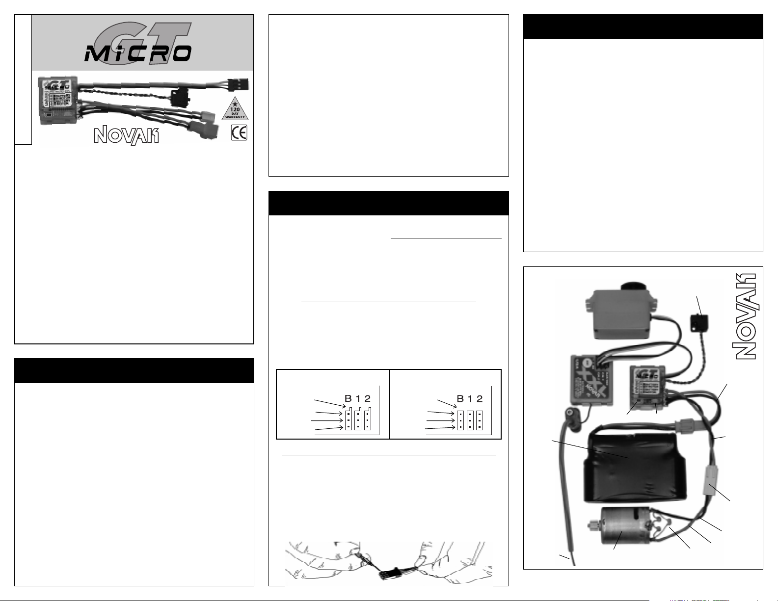
STEP 2 MOUNTING ELECTRONICS
1. DETERMINE BEST ESC MOUNTING LOCATION
The ESC should be positioned away from the receiver
and antenna as shown in the Set-Up photo below. Choose
a mounting position that will keep the power wires from
obstructing movement of suspension or the motor pod.
2. INSTALL SPEED CONTROL
Use the included double-sided tape to mount the ESC.
3. INSTALL ON/OFF SWITCH
Determine a convenient place to mount the switch where
it will be easy to get to. Mount the switch using a piece
of double-sided tape or with a screw through the hole in
the base of the switch housing.
4. INSTALL RECEIVER
Mount the receiver as far from the motor, power wires,
battery, and servo as possible. These components all emit
radio noise when the throttle is being applied. On graphite
or aluminum, place the receiver on edge with the crystal
and antenna as far above the chassis as possible. Mount
the antenna close to the receiver and trail any excess
wire off the top of the antenna.
SET-UP PHOTO
4-7 cell
battery
pack
trail excess
wire off top
of antenna
mast
SET button
sub-540 size
motor
ON/OFF
switch
status LED
(–)
(+)
three 0.1µF capacitors
battery leads
(red connector)
twist
motor
wires to
reduce
RF noise
motor leads
(yellow connector)
black wire
red wire
www.teamnovak.com
Page 2
STEP 3 CONNECTING ELECTRONICS
Refer to Set-Up photo on front
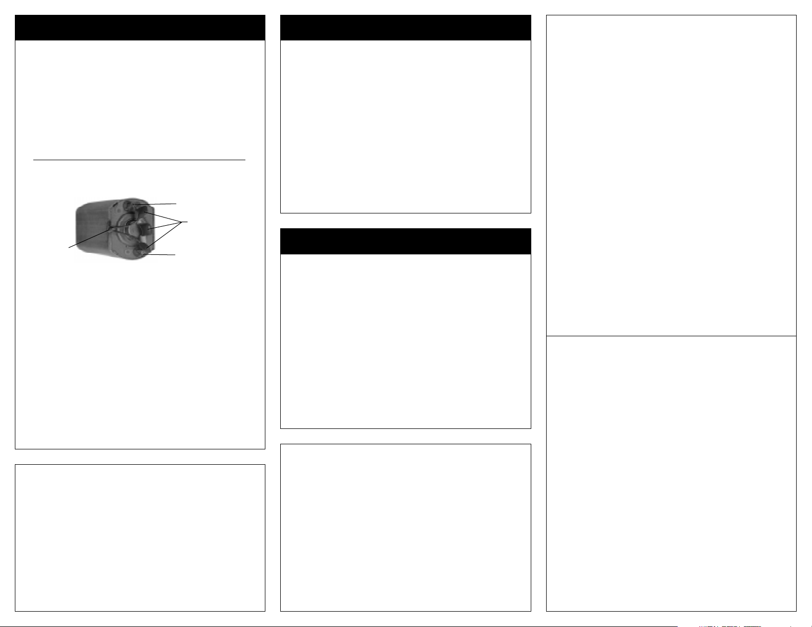
1. CHECK MOTOR CAPACITOR INSTALLATION
Electric motors generate radio noise that can interfere
with your receiver and cause radio problems. Three 0.1µF
(50V) non-polarized, ceramic capacitors are included and
must be installed on every motor to help reduce the noise
generated by the motor and to prevent ESC damage. If
your motor does not have all 3 capacitors shown below,
they must be added
in Novak kit #5620
0.1µF (50V) capacitors should be soldered between:
• POSITIVE (+) motor tab & NEGATIVE (
• POSITIVE (+) motor tab & GROUND (motor can).
• NEGATIVE (
Ground
(motor can)
2. NO EXTERNAL SCHOTTKY DIODE IS REQUIRED
The Micro GT speed control does NOT require an external Schottky diode.
3. CONNECT SPEED CONTROL TO THE RECEIVER
After the proper input plug plastic has been installed to
match the receiver (Refer to Step 1), plug the speed control
into the THROTTLE CHANNEL (#2) of the receiver.
4. CONNECT SPEED CONTROL TO THE BATTERY PACK
Plug the RED Micro connector from speed
4 to 7 cell battery pack (1.2 volts DC/cell).
*Note: Use of non-OEM
5. CONNECT SPEED CONTROL TO THE MOTOR
Plug the YELLOW Micro connector from speed
into
the connector on the motor.
*Replacement battery/motor leads w/Micro connectors available in Novak kit #5330.
TIP: Twisting the motor wires once or twice as they go to the motor
can help reduce any radio noise emitted from the wires.
CUSTOMER SERVICE
Monday-Thursday: 8:00am-5:00pm (PST)
Friday: 8:00am-4:00pm
(949) 833-8873 • FAX (949) 833-1631
e-mail: cs@teamnovak.com
©2005 Novak Electronics, Inc. • All Rights Reserved
No part of these operating instructions may be reproduced without
the written permission of Novak Electronics, Inc.
All Novak speed controls are designed and manufactured in the U.S.A.
Micro GT, Polar Drive Technology, Radio Priority Circuitry,
Set-Up, Smart Braking Circuitry, and Reverse Disable Circuitry
trademarks of Novak Electronics, Inc.
Printed in the U.S.A. 1/2005 • #55-1875-1
(0.1µF capacitors are also available
).
-) motor tab.
-) motor tab & GROUND (motor can).
Positive (+) motor tab
µ
F Capacitors
0.1
Negative (–) motor tab
control into a
Micro
connectors voids warranty.
control
(closed every other Friday)
One-Touch
are all
STEP 4 TRANSMITTER ADJUSTMENTS
1. Set HIGH ATV or EPA to maximum setting.
[Amount of throw at full throttle]
2. Set LOW ATV, EPA, or ATL to maximum setting.
[Amount of throw at full brakes]
3. Set EXPONENTIAL to zero setting.
[Throttle channel linearity]
4.
Set THROTTLE CHANNEL REV. SWITCH to either position.
[Do not change switch position after programming]
5. Set THROTTLE CHANNEL TRIM to middle position.
[Adjusts neutral position/Increases or decreases coast brakes]
6. Set ELECTRONIC TRIGGER THROW ADJUSTMENT to
70% throttle and 30% brake throw (or 7:3).
[Adjusts trigger throw on electronic/digital pistol-grip transmitters]
7. Set MECHANICAL TRIGGER THROW ADJUSTMENT
to position with 2/3 throttle and 1/3 brake throw.
[Adjusts trigger throw on mechanical/analog pistol-grip transmitters]
STEP 5 PROGRAMMING SPEED CONTROL
With ESC connected to receiver & charged battery pack:
1. TURN ON THE TRANSMITTER, THEN SPEED CONTROL
2. PRESS AND HOLD SPEED CONTROL’S SET BUTTON
With transmitter throttle at neutral, press and hold the
ESC SET button until the status LED turns solid red.
RELEASE ESC SET BUTTON WHEN LED IS RED
3.
4.
PULL TRANSMITTER THROTTLE TO FULL-ON POSITION
Hold it there until the status LED turns solid green.
NOTE: Motor will not run during programming even if connected.
5. PUSH TRANSMITTER THROTTLE TO FULL-REVERSE
Hold it there until the status LED blinks green.
6. RETURN TRANSMITTER THROTTLE TO NEUTRAL
Status LED will turn solid red, indicating that throttle is
at neutral and proper programming has been completed.
If transmitter settings are changed, programming must be repeated.
If you experience any problems, turn off ESC and repeat programming.
PRODUCT WARRANTY
The Micro GT is guaranteed to be free from defects in materials or workmanship
for a period of 120 days from original date of purchase (verified by dated, itemized
sales receipt). Warranty does not cover incorrect installation, components worn
by use, damage from using fewer than 4 or more than 7 cells (1.2 volts DC/cell)
input voltage, cross-connection of the battery/motor, using the same-gender
connectors on ESC, not using OEM Micro connectors or using 540-size or larger
, reverse voltage application, damage resulting from thermal overload
motors
installing three 0.1µF (50V) capacitors on motors, splices to input or
harnesses, damage from disassembling case, replacing wires, or excessive
when using SET button, tampering with internal electronics, allowing water,
moisture, or other foreign material to enter ESC or get onto PC board,
installation/wiring of battery/motor leads, alternate input plug plastic
receiver battery pack, or FET servo, allowing exposed wiring to short-circuit
leaving battery pack connected to ESC while unattended or
of time, or any damage caused by crash, flooding, or act of God.
In no case shall our liability exceed the product's original cost. We reserve the
right to modify warranty provisions without notice.
Because Novak Electronics, Inc. has no control over connection and use of the
ESC, no liability may be assumed nor will be accepted for damage resulting
from the use of this product. Every ESC is thoroughly tested and cycled before
leaving our facility and is, therefore, considered operational. By the act of connecting/operating ESC, the user accepts all resulting liability.
for extended periods
, not
switch
force
incorrect
, external
TROUBLE-SHOOTING GUIDE
•NOT ALL TRANSMITTERS HAVE THESE ADJUSTMENTS•
Steering Channel Works But Motor Will Not Run
• Speed control has thermally shut down––Allow ESC to cool
down––Use milder motor or smaller pinion gear––Check vehicle’s
drive train for free operation.
• Check motor connections. Check motor.
•
Make sure ESC is plugged into the throttle channel (#2) of receiver.
Check throttle channel operation with a servo. Check wiring color
sequence of receiver signal harness.
• Possible internal damage––Refer to Service Procedures.
Receiver Glitches/Throttle Stutters During Acceleration
• Motor capacitors broken or missing––Refer to Step 3.
• Receiver or antenna too close to speed control, power wires,
battery, or motor––Refer to Step 2.
• Bad connections––Check wiring and connectors.
• Motor brushes worn––Replace/rebuild motor.
•
Excessive motor current––Use milder motor/smaller pinion gear.
Motor and Steering Servo Do Not Work
• Check wires, receiver signal harness wiring & color sequence,
radio system, crystals, battery/motor connectors, & battery pack.
• Possible internal damage––Refer to Service Procedures.
Model Runs Slowly/Slow Acceleration
• Check motor and battery connectors––Replace if needed.
• Bad battery or motor––Check operation with another.
•
Incorrect transmitter/ESC adjustment––Refer to Steps 4 & 5.
Motor Runs Backwards
• Motor wired backwards––Check wiring and reverse.
ESC Is Melted Or Burnt/ESC Runs With Switch Off
• Internal damage––Refer to Service Procedures.
*For more assistance call our Customer Service Department or check our website.
SERVICE PROCEDURES
Before sending your speed control in for service, review the TroubleShooting guide and the instructions.
when other problems exist.
After reviewing the instructions, if you feel that your ESC requires
service, please obtain the most current product service
and pricing by one of the following methods:
WEBSITE: Print a copy of the PRODUCT SERVICE FORM from
the SERVICE section of the website. Fill out the needed information
on this form and return it with the Novak product for servicing.
PHONE/FAX: If you do not have access to the internet,
contact our customer service department by phone, or fax
listed in the CUSTOMER SERVICE section below, and they will
supply you with current service options.
WARRANTY SERVICE: For warranty work, you MUST CLAIM
WARRANTY on the PRODUCT SERVICE FORM and include a valid
cash register receipt with purchase date on it, or an invoice
from previous service work. If warranty provisions have been
voided, there will be service charges.
,
ADDITIONAL NOTES:
•
Dealers/distributors are not authorized to replace Novak products
thought to be defective.
• If a hobby dealer returns your Novak product for service, submit
a completed PRODUCT SERVICE FORM to the dealer and make
sure it is included with the product.
• Novak Electronics, Inc. does not make any internal electronic
components (transistors, resistors, etc.) available for sale.
ESC may appear to have failed
options
please
as
 Loading...