

Novak Kinetic 1S User Manual
timing indicator led
To conform to ROAR’s Sportsman Class racing rules and help race organizers
monitor driver compliance in non-timing race classes, we have included a
feature in this speed control that indicates when the ESC has its electronic
motor timing advancement feature activated.
At all times when the speed control is powered ON and the Dynamic Motor
Timing is turned ON and set to a level greater than zero timing advance,
the ESC’s white status LED will be illuminated during normal operation.
motor hall sensor test
The Hall Sensor Test diagnostic feature in the Kinetic allows you to easily check
the sensors in the brushless motor connected to the ESC to determine if they
are operating normally. This will help you pinpoint the cause of problems in
your system, and hopefully reduce down time and expenses associated with
sending your product in for service when you can resolve the issue yourself.
To access this feature, simply follow these steps:
1. Follow the steps in the ‘CUSTOM PROGRAMMING OPTIONS’ section
to access the Hall Sensor Test option via the ESC’s SET button.
2. Slowly rotate the motor’s output/pinion shaft. If motor is installed in
a vehicle, slowly rotate the drive train so that the motor also rotates.
3. The status LEDs on the speed control should cycle through illuminating
the BLUE, YELLOW, and RED status LEDs.
If the BLUE, YELLOW, and RED LEDs light up one after another as the motor’s
shaft is rotated, the Hall Sensors in the motor are operating normally.
If any one of the BLUE, YELLOW, or RED status LEDs do not light while rotating
the motor’s shaft, there is a either a problem with the Sensor Harness Cable
(or its connections either at the motor end or the ESC end) or with the actual
Hall Effect Sensors in the motor’s timing section.
If your motor has a user-replaceable double-ended sensor harness, replace
it with another one to determine if this is this source of the problem. If, after
replacing the harness, all three of the LEDs still do not light up, it would
appear that one of the sensors inside the motor has been damaged--replace
the timing section of your motor, or if your motor is not user-rebuildable,
send it in the manufacturer for the appropriate service.
voltage cut-off circuitry
The Kinetic ESC features Novak’s Smart-Stop Voltage Cut-Off Circuitry built-in,
and when used properly will allow you to safely use LiPo and LiFe batteries,
without letting the cells drop below their critical safety voltage.
The default in the ESC is LiPo voltage cut-off. If using NiMH or NiCd cells,
you will need to switch this feature off. If using LiFe cells, you will need to
switch to the LiFe battery setting.
Note: Whenever the speed control’s One-Touch Programming is
performed, this setting will revert to the LiPo default setting.
DO NOT USE LiPo/LiFe BATTERIES WITH VOLTAGE CUT-OFF TURNED OFF
temperature monitoring
The Kinetic has a built-in diagnostic temperature monitoring feature that lets
you quickly check the ESC’s operating temperature at any time.
While connected to a battery and powered ON, simply tap the ESC’s SET
button and one of the on-board LED lights will flash 4 times to indicate the
operating temperature of the speed control.
WHITE flashing LED = normal operating temp--under 135°F (57°C).
BLUE flashing LED = medium operating temp--136-147°F (58-64°C).
YELLOW flashing LED = hot operating temp--148-167°F (65-75°C).
GREEN flashing LED = hotter operating temp--168-194°F (76-90°C).
RED flashing LED = hottest operating temp--195-215°F (91-102°C).
You are now pushing the ESC extremely hard and should be very
careful to avoid overheating and possible thermal shut-down.
All LEDs flashing = DANGEROUS operating temp--216-239°F (103-115°C).
---Reduce the pinion size to avoid overheating and potential ESC damage---
www . t e a m n o v a k . c o m
Your ESC is now about to thermally shut-down.
P8
trouble-shooting guide
Steering Channel Works But Motor Will Not Run
• Possible receiver damage––Check operation with a different receiver.
• Possible internal damage––Refer to ‘SERVICE PROCEDURES’ section.
• Check motor or motor connections.
• Make sure ESC is plugged into the throttle channel of receiver. Check wiring color
sequence of receiver signal harness (Refer to STEP 1 in Basic Set-Up Guide).
Receiver Glitches/Throttle Stutters During Acceleration
• Receiver or antenna too close to ESC, power wires, battery, or motor.
• Bad motor sensors, sensor harness, or connections––Check wiring, sensor harness, &
connections, perform hall sensor test (Refer to ‘MOTOR HALL SENSOR TEST’ section).
• Low voltage to receiver––Try Novak Glitch Buster capacitor on receiver to help
retain power during high current draw situations (Novak accessory #5626).
• Power Trans-Cap Module damaged/missing––Replace Power Trans-Cap Module.
• Battery pack damaged or weak––Try a different battery pack.
• Motor magnet weak or overheated––Replace rotor
• Excessive current to motor—Use a milder motor or a smaller pinion gear.
• Untidy wires or signal and power wired bundled together. Input harness and servo
wires should be bundled separately. Power wires should be as short as possible.
Motor and Steering Servo Do Not Work
• Check wires, receiver signal harness wiring & color sequence, radio system, crystals,
battery/motor connectors, & battery pack.
• Possible receiver damage––Check operation with a different receiver.
• Possible internal damage––Refer to Service Procedures.
Motor Runs Backward
•
Reverse motor rotation direction––Refer to ‘CUSTOM PROGRAMMING OPTIONS’ section.
• Improper One-Touch set up––Refer to ‘ONE-TOUCH PROGRAMMING’ section.
Timing Does Not Operate Properly
• Improper gearing––Refer to ‘PROPER GEAR SELECTION’ section.
•
Motor rotation is set to clockwise––
in counter-clockwise rotation direction
• Timing Set Point set incorrectly––Refer to
Speed Control Runs Excessively Hot
• Electronic motor timing set too high––reduce timing level setting in ESC.
•
Gear ratio too low––Increase gear ratio/Reduce pinion
• Motor is damaged––Try a different motor.
Model Runs Slowly/Slow Acceleration
•
Gear ratio too high––Reduce gear ratio/Increase pinion
• Check battery & connectors––Check battery pack & connectors. Replace if needed.
• Incorrect transmitter/ESC adjustment––Refer to ‘TRANSMITTER ADJUSTMENTS’.
• Power Trans-Cap Module damaged/missing––Replace Power Trans-Cap Module.
ESC Is Melted Or Burnt/ESC Runs With Switch Off
• Internal damage––Refer to Service Procedures.
No Power to the BEC
• Check power wire connections to your battery, ESC and BEC unit.
• Check that the input harness from the BEC is plugged into the receiver correctly
and the red wire from the ESC’s input harness is removed.
• Be sure that the BEC unit’s power switch is turned ON.
•
Blue status LED on solid at neutral––Minimum Brake is set to value greater than 0%.
• Yellow status LED on solid at neutral––Drag Brake is set to value greater than 0%.
• Red & Green status LEDs on solid––Check input signal harness connections at ESC
and receiver. Check input signal harness wiring sequence––Refer to STEP 1.
• Red status LED on solid & Green LED blinking––Check motor sensor harness
connection. Possible internal motor damage.
• Blue & Green status LEDs both blinking. Possible ESC shut-down due to locked
rotor detection––return throttle to neutral position to regain motor control––check
vehicle’s drive train for free operation.
• Blue & Red status LEDs blinking. Possible ESC thermal shut-down––Check gear
ratio & free operation of drive train for possible overloading/ESC is being severely
over-loaded––allow system to cool & return throttle to neutral position to regain
motor control. LEDs will continue to blink until system is cooled down.
• Blue & Yellow status LEDs blinking. Possible Motor thermal shut-down––Check
gear ratio & free operation of drive train for possible overloading/Motor is being
severely over-loaded––allow system to cool & return throttle to neutral position to
regain motor control. LEDs will continue to blink until system is cooled down.
• Blue & Green (Locked Rotor Detection), Blue & Red (ESC Thermal Shut-Down), or
Blue & Yellow (Motor Thermal Shut-Down) status LEDs blinking. ESC may have shutdown & ESC’s neutral point is too far off to sense that transmitter throttle has
been returned to neutral (Refer to ‘ONE-TOUCH’ & ‘TRANSMITTER ADJUSTMENTS’).
•
Green & White status LEDs blinking. RPM safety limit reached & physical limit of motor
bearings being reached/Possible over-rev condition. Increase gear ratio or reduce pinion.
• White status LED blinking. ESC timing is turned ON. ESC is operating normal.
• Red & Green status LEDs toggling. LiPo/LiFe Safety Cut-Off voltage reached. Remove
and charge/replace battery pack.
n
ovalink interface
In addition to on-board programming, the Kinetic
can be fine-tuned via Novak’s fully adjustable PC
interface, the NovaLinkTM Programming Interface
(#5440). The NovaLink includes an ESC adaptor
module to plug into the input harness, a USB cord
to connects the adaptor to the computer, and a
NovakLink CD to install the required PC software.
ESC parameter values are easily typed in or input via user-friendly graphic controls.
Each personalized set of ESC parameters can be stored on the PC and recalled later
or shared with other drivers to find the best set-up for given tracks, vehicles, and
conditions. Both the NovakLink and your ESC are easy to keep up-to-date, thanks
to software & firmware updates available for download from the Novak web site.
error codes
Check Novak’s web site for additional information.
(Refer to motor manufacturer’s website).
Electronic motor timing advancement only functions
(refer to ‘CUSTOM PROGRAMMING OPTIONS’)
‘CUSTOM PROGRAMMING OPTIONS’ section
(refer to ‘PROPER GEAR SELECTION’).
(refer to ‘PROPER GEAR SELECTION’).
NovaLinkTM
(#5440)
.
kinetic track guide
2-2011#55-1741P-1 Rev.2
The Kinetic 1S Racing Brushless ESCs (#1741)
is factory loaded with well over a dozen
programmable features. While this may seem
overwhelming at first glance, this Kinetic 1S
Track Guide was designed to keep with you
at the track to use as a quick-reference and
help walk you through the programming of
all of the speed control’s features.
Take the time to thoroughly read through this programming guide before
operation to fully understand the different ESC parameters, and how they
can be used to fine tune your ESC’s feel and performance. Most importantly,
enjoy all of the technical benefits and features the Kinetic ESCs have to offer.
Visit our web site for up to date information and to learn more, and check out
the NovaLinkTM PC Interface (#5440) for even more customization options.
one-touch programming
With the ESC connected to (at least) a charged battery pack, the receiver, and the
brushless motor’s sensor harness:
.
1. TURN ON THE TRANSMITTER’S POWER
2. PRESS & HOLD ESC’S ONE-TOUCH/SET BUTTON
3. TURN ON THE SPEED CONTROL’S POWER
With transmitter throttle at neutral, and still pressing the SET button, slide the
ESC’s ON/OFF switch to ON position.
4.
CONTINUE HOLDING SET BUTTON UNTIL RED LED COMES ON
5. RELEASE SET BUTTON AS SOON AS LED TURNS RED
6.
PULL TRANSMITTER THROTTLE TO FULL-ON POSITION
Hold it there until the green status LED turns solid green.
Note: Motor will not run during programming even if connected.
7. PUSH TRANSMITTER THROTTLE TO FULL-BRAKE/REVERSE
Hold it there until the green status LED blinks green.
8. RETURN TRANSMITTER THROTTLE TO NEUTRAL
The red status LED will turn solid red, indicating that speed control is at neutral and
that proper programming has been completed. Blue & yellow LEDs will also be on
indicating Minimum Brake (blue) & Drag Brake (yellow) settings are at levels above 0%.
If transmitter settings are changed, the One-Touch Programming must be repeated.
If you experience any problems, turn off ESC and repeat One-Touch.
NOTE: Whenever the One-Touch Programming is performed, the speed control
will automatically revert back to the factory-default settings.
esc parameters
1. Minimum Brake (1 of 10) .......................................................... 0-30%
2. Drag Brake (1 of 10) .................................................................. 0-30 %
3. Minimum Drive (1 or 10) ...........................................................0-15%
4. Timing Level
5. Timing Set Point
6. Current Limit (1 of 10) ........................................................... OFF-50 A
7. Dead Band (1 of 5) ...................................................................... 2-8 %
8. Throttle Curve (1 of 2) ............................................ Linear/Exponential
9. Brake Curve (1 of 2) ................................................ Linear/Exponential
10.
Brake Frequency (1 of 10) ...............................................1.67-13.7 KHz
11.
Brake End Point (1 of 10)....................................................... 10-100%
12.
Drive Frequency (1 of 10) ........................................................7-16KHz
13.
Reverse ................................................................................... OFF/ON
14.
Motor Rotation ..................................................................... CCW/CW
15.
Voltage Cut-Off .............................................................. OFF-LiPo-LiFe
(1 of 8)
....................................................... 0-55°(+Boost)
(1 of 8)
.............................................. 2000-6500 RPM
timing esc warning
Due to the nature of timing advance speed controls, motor tolerances &
settings, vehicle performance, and track conditions, it has become virtually
impossible to provide installation and operation recommendations that
will allow you to use these speed controls and motors at their highest
performance levels without the potential for unwanted damage.
You must, use extreme caution when setting up these electronics and
carefully test your application to avoid overloading and overheating
either the speed control or the motor.
These are racing electronics used
in racing conditions, and therefore damage as the result of excessive
overheating will not be covered under the product’s factory warranty.
Electronic motor timing advancement can generate extrememly high speeds and
result in an uncontrollable vehicle. Use caution when operating vehicle and do not
operate around other people or in an unsafe manner to avoid injuries or damage.
proper gear selection
Motor operating temperature is the ONLY
way to properly set vehicle gearing
The Motor and Speed Control should not exceed
160°F MAX at any time during run!
Change the gearing to avoid overheating!
transmitter adjustments
Transmitter adjustments may not be needed to operate the Kinetic ESC.
However, if you have any problems with ONE-TOUCH PROGRAMMING, adjust
the transmitter as follows and repeat the ONE-TOUCH PROGRAMMING step.
THROTTLE CHANNEL ADJUSTMENTS
A.
Set HIGH ATV or EPA to 100% setting. [amount of throw at full throttle]
B.
Set LOW ATV, EPA, or ATL to 100% setting. [amount of throw at full brakes]
C. Set EXPONENTIAL to zero setting. [throttle channel linearity]
D.
Set THROTTLE CHANNEL REV. SWITCH to either position.
E. Set THROTTLE CHANNEL TRIM to middle setting.
[adjusts neutral position/increases or decreases coast brakes]
F.
Set ELECTRONIC TRIGGER THROW ADJUSTMENT to 50%
50% brake throw–best for reversible ESCs.
[adjusts trigger throw electronic/digital pistol-grip transmitters]
G.
Set MECHANICAL TRIGGER THROW ADJUSTMENT to position
throttle and 1/2 brake throw.
throttle and
with 1/2
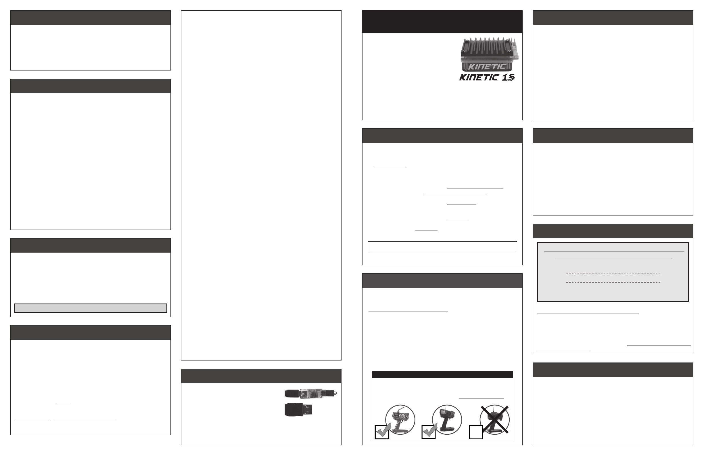
GOOD QUALITY RADIO SYSTEM SUGGESTED
With the higher performance of brushless systems, undesirable radio system
noise may occur when used with lower quality radio systems. 2.4GHz radio
systems are the best to use. FM radio systems are acceptable, as long as
the system is high quality. AM radio systems are NOT recommended.
2.4 GHz
Best to use
FM
OK to use
AM
Do not use
NOT ALL TRANSMITTERS HAVE THESE ADJUSTMENTS
Free-running your brushless motor in a no-load condition can cause rotor failure
& ESC transistor damage that will not be covered by the product’s warranty.
Because of the potential danger of overheating, ESC/motor damage & failure,
you must start with VERY small pinion sizes and check ESC & motor
temperatures at multiple times throughout the initial runs. This is the only
way to ensure that you are not causing excessive heating.
If ESC & motor temperatures remain low & stable, you can slowly increase
the pinion size while again monitoring the temperatures to determine the
safe gearing for your vehicle, motor, and climate/track conditions. Because
these variables can change or be modified, you MUST continually monitor
ESC & motor temperatures to protect your electronics from damage.
temperature OVERLOAD
The Kinetic 1S ESCs has built-in ESC temperature overload protection
that will turn off the Dynamic Timing Advance feature and will also limit
the power to the motor in an attempt to prevent thermal overloading of
the speed control. While this feature can not guarantee the survival of
the speed control when subjected to conditions that produce excessive
heating of the electronics, it does provide another tool that you can use
to avoid extensive damage.
If you notice a significant decrease in performance of your brushless
system during a run, immediately check the operating temperatures
of the speed control and the motor. Reduce gearing or ESC timing
settings to lower operating temperatures!
P5
DO NOT FREE-REV MOTOR
!

CUSTOM programmiNG options -- advanced
kinetic 1S software flow chart
The Kinetic 1S ESC features over
a dozen parameters that can be
customized to fine-tune the ESC’s
feel & response to your liking.
The flow chart bel ow and the
adju stment steps to the right
describe the different parameters
and how they effect the ESC.
One-Touch Programming must be
completed before customization of
parameters, as all ESC parameters
are defaulted back to the factory
settings whenever the One-Touch
Programming is performed.
DEFAULT SETTINGS FOR
THE ESC PARAMETERS ARE
LISTED IN BOLD IN THE
TABLES TO THE RIGHT
TO CHANGE PARAMETER SETTINGS:
1. C O NNEC T T HE ES C T O A
CH ARGE D BATTERY PACK,
REC E IVE R , AN D MO T O R’S
SENSOR HARNESS
2. S L IDE T H E ESC’s ON / O F F
SWITCH TO ‘ON’ POSITION
3. WITH ESC AT NEUTRAL, PRESS
& HOLD SET BUTTON
Release ESC’s SET button once LEDs
are lit for the desired setting.
To skip a para meter, continue
to press & hold SET button until
desired parameter is reached.
4. SELECT PARAMETER VALUE
LE D f la sh es to i nd ic ate active
setting (refer to tables at right).
Quick press & release SET button
to select desired setting.
5. PRESS & HOLD SET BUTTON
TO STORE NEW SELECTION
When SET button is pressed and
he ld for ab ou t 1 s eco nd , the
new selection is stored in ESC’s
memory—
to indicate ESC is exiting programming
& ESC returns to neutral.
There is no time constraint during
selection of custom parameters.
Status LEDs will scroll across
THROTTLE and
brake CURVES
The Kinetic features both linear and
exponential throttle & brake curves.
The ‘Expo’ curves provide a more
controllable bottom end response.
100%
Linear
Motor Output
Expo
0
Trigger Position
100%
MIN. BRAKE
DRAG BRAKE
MIN. DRIVE
TIMING LEVEL
GREEN-RED-WHITE
TIMING SET PT.
YELLOW-GREEN-RED-WHITE
CURRENT LIMIT
YELLOW-GREEN-WHITE
DEAD BAND
THROTTLE CURVE
BRAKE CURVE
BRAKE FREQ.
BRAKE END PT.
YELLOW-RED-WHITE
continue holding ESC’s SET button to skip steps here
DRIVE FREQ.
YELLOW-GREEN-RED
MOTOR ROTATION
VOLTAGE CUT-OFF
HALL SENSOR TEST
BLUE-YELLOW-RED
@NEUTRAL
RED LED on solid
press & hold SET button
BLUE
BLUE & YELLOW
YELLOW
BLUE & GREEN
GREEN & WHITE
RED & WHITE
RED
GREEN
REVERSE
BLUE-GREEN-RED
YELLOW & RED
PROFILE
all LEDs (flashing)
# flashes
**profile 2 via NovaLink
if pressed within 3 sec.
of all LEDs flashing
active profile changed
if not pressed within
3sec. of all LEDs flashing
LEDs roll off
ESC exits programming
@NEUTRAL
RED LED on solid
=
active profile
(1-2**)
TM
minimum brake
#1 MINIMUM BRAKE SETTINGS
Amount of braking applied with the first pulse of transmitter throttle information sent.
>> Increasing starts braking at a higher level. Minimizes the trigger
throw required before effective braking is applied with heavy vehicles.
Setting (# of flashes) 1 2 3 4 5 6 7 8 9
Minimum Brake
(%)
:
0 3 6 9 12 15 18 21 24 30
(1 of 10)
drag brake
#2 DRAG BRAKE SETTINGS
Amount of braking being applied while transmitter is at neutral. AKA ‘coast’ brakes.
>> Increasing this setting makes the motor slow down more without
pushing the transmitter’s trigger into the brake/reverse direction.
Setting (# of flashes) 1 2 3 4 5 6 7 8 9
Drag Brake (%):
(1 of 10)
BLUE & YELLOW LEDs
0 3 6 9 12 15 18 21 24 30
minimum drive
#3 MINIMUM DRIVE SETTINGS
Amount of forward drive applied with first pulse of transmitter throttle information sent.
>> Increasing starts forward drive at a higher level. Minimizes trigger
throw required before effective drive is applied with heavy vehicles.
Setting (# of flashes) 1 2 3 4 5 6 7 8 9
Minimum Drive
(%)
:
0 1 2 3 4 6 8 10 12 15
(1 of 10)
TIMING level
#4 TIMING LEVEL SETTINGS
The maximum degrees of Dynamic Timing Advance applied to the motor.
>>
Increasing this setting will increase the maximum amount of electronic
motor timing that is applied to the motor throughout the throttle band.
Setting (# of flashes) 1 2 3 4 5 6* 7* 8*
Timing Level
Setting #1 disables all timing to meet ROAR’s Sportsman Class racing specs.
WARNING: DO NOT FREE-REV MOTOR TO CHECK TIMING SETTINGS
*Timing Levels 6-8 produce excessive heating & must be used with caution.
Physical motor timing should be set to 30° (“N” on older Ballistic motors)
Note: Do NOT use Timing Advance with 3.5-5.5 turn 540-Size motors.
(degrees):
(1 of 8)
GREEN-RED-WHITE LEDs
0 10 15 20 30 40 55
TIMING SET POINT
#5 TIMING SET POINT
The RPM trip point at which Dynamic Timing Advance is applied.
>> Increasing this setting will decrease the RPM at which the electronic
motor timing advancement comes on.
Setting (# of flashes) 1 2 3 4 5 6 7 8
Timing Set Pt
(x1000 RPM)
(1 of 8)
YELLOW-GREEN-RED-WHITE LEDs
6.5 5.5 4.5 4.0 3.5 3.0 2.5 2.0
:
CURRENT LIMIT
#6 CURRENT LIMIT SETTINGS
The maximum amount of current the ESC will allow the motor to draw.
>> Increasing this setting reduces the maximum current that can pass
through the ESC to reduce temperatures or for limiting wheel slip.
Setting (# of flashes) 1 2 3 4 5 6 7 8 9
Current Limit
P6
(Amps)
:
OFF
Note: ESC Parameter values are subject to change due to ongoing development. Refer to our web site for updated values and more information on ESC param
(1 of 10) YELLOW-GREEN-WHITE LEDs
Hi – – – – – – –> Lo
BLUE LED
10
10
YELLOW LED
10
Boost
10
dead band
#7 DEAD BAND SETTINGS
The space between Minimum Brake and Minimum Drive, with Neutral in the middle.
>>
Increasing this setting increases the amount of ‘free play’, or distance your
transmitter’s trigger must move before forward drive or braking begins.
Setting (# of flashes) 1 2 3 4 5
Dead Band (%):
(1 of 5)
BLUE & GREEN LEDs
2 3 4 5 8
THROTTLE CURVE
#8 THROTTLE CURVE SELECTION
How the ESC’s throttle (or forward drive) responds to the transmitter’s trigger input.
>> Changing this setting changes how the throttle responds to your
transmitter’s trigger movement. The ‘Expo’ curve gives a less responsive,
or more forgiving low-end acceleration.
Setting (# of flashes) 1 2
Throttle Curve:
(1 of 2)
GREEN & WHITE LEDs
Linear Expo
BRAKE CURVE
#9 BRAKE CURVE SELECTION
How the ESC’s brakes respond to the transmitter’s trigger input.
>> Changing this setting changes how the brakes respond to your
transmitter’s trigger movement. The ‘Expo’ curve gives a less responsive,
or more forgiving low-end braking.
Setting (# of flashes) 1 2
Brake Curve:
(1 of 2)
RED & WHITE LEDs
Linear Expo
BRAKE FREQUENCY
#10 BRAKE FREQUENCY SELECTION
How the ESC’s braking response feels with respect to the transmitter’s trigger input.
>> Increasing the Brake Frequency makes the brake response feel
smoother and more controllable.
Setting
(# of flashes)
Brake Freq.
Note: Brake/Drive Frequency is not adjustable with Expo Brake/Drive Curves.
(KHz)
1 2 3 4 5 6 7 8 9
:
1.6722.25
(1 of 10)
2.5
3
3.5 4.5
5.75
BRAKE END POINT
#11 BRAKE END PT. SELECTION
The percentage of the ESC’s braking power that can be attained as well as the
transmitter trigger throw required to reach that power.
>> Decreasing this setting reduces the maximum braking power and the
usable distance of the transmitter’s brake trigger throw. The ‘Linear’ or
‘Expo’ brake curves will be cut off at this point, and you will get that
percentage/level of braking for the rest of the transmitter’s trigger throw.
Setting (# of flashes) 1 2 3 4 5 6 7 8 9
Brake End Pt. (%):
Note: At high timing settings, use 100% (setting 10) Brake End Point.
10 20 30 40 50 60 70 80 90 100
(1 of 10) YELLOW-RED-WHITE LEDs
DRIVE FREQUENCY
#12 DRIVE FREQUENCY SELECTION
How the ESC’s throttle response feels with respect to the transmitter’s trigger input.
>> Increasing the Drive Frequency makes the throttle response feel
smoother and more controllable.
Setting
(# of flashes)
Drive Freq.
(KHz)
1 2 3 4 5 6 7 8 9
:
16
15.2
(1 of 10)
13.8
13 12 11 10 9.5 8 7
GREEN LED
eters.
RED LED
10
13.7
10
10
10
reverse
#13 REVERSE SELECTION
>> Changing this setting activates or deactivates the ESC’s reverse
functionality. When OFF, ESC has forward and brakes only. When ON,
ESC has forward with brakes, then reverse with 2nd push of trigger.
Setting (# of flashes) 1 2
Reverse:
(1 of 2)
YELLOW-GREEN-RED LEDs
OFF ON
motor rotation
#14 MOTOR ROTATION SELECTION
>>
Changing this setting changes the rotational direction of the motor’s
output/pinion shaft. Counter-clockwise rotation is standard in
remote control vehicles. For optimal motor performance, use counterclockwise rotation instead of reversing the transmitter’s throttle
channel throw. Advanced timing is not available in clockwise rotation.
Setting (# of flashes) 1 2
Rotation Direction:
CCW Q CW P
(1 of 2) BLUE-GREEN-RED LEDs
voltage cut-off
#15 VOLTAGE CUT-OFF SELECTION
>> Changing this setting enables or disables the ESC’s Smart Stop
cut-off circuitry, and also sets the voltage cut-off point based on what
type of batteries are being used in the vehicle’s main battery pack.
DO NOT USE LiPo/LiFe BATTERIES WITH VOLTAGE CUT-OFF TURNED OFF
Setting (# of flashes)
Voltage Cut-Off Type:
1 2 3
(
NiMH/NiCd
OFF
(1 of 3) YELLOW & RED LEDs
)
LiPo LiFe
hall sensor test
#16 MOTOR SENSOR TEST
>>
This diagnostic feature that allows you to easily check your brushless
motor’s hall effect sensors & your sensor harness and its connections
at the ESC & motor. Once activated, rotate the motor’s output/pinion
shaft and the appropriate LED will light up if a signal is received for
its sensor in the motor. Refer to ‘MOTOR HALL SENSOR TEST’ section.
Motor Hall Sensor A B C
LED Color:
BLUE YELLOW RED
BLUE-YELLOW-RED LEDs
throttle profile
#17 THROTTLE PROFILE SELECTION
>> Changing this setting changes ESC’s active Throttle Profile.
Note: Profile #2 can only be activated by syncing ESC with the
NovaLinkTM interface, and is only programmable via the NovaLink
software. You can switch from Profile 2 to 1 on the ESC.
Setting (# of flashes) 1 2
Throttle Profile:
Built-In Custom
restoring factory defaults
Every time you perform the One-Touch Set-Up, the
speed control will automatically revert back to
Throttle Profile #1, and the factory default settings
are restored for each of the ESC parameters.
www . t e a m n o v a k.c o m
P7
(1 of 2)
most
ALL LEDs
 Loading...