

Page 1
MOTOR MAINTENANCE MOTOR MAINTENANCE
• CHECK ALL MOTOR SCREWS for loosening at regular intervals, just like
other hardware on your vehicle. Note: The 3 main socket head screws
that hold the motor together may require tightening after a few runs of
the motor. Also check the 3 flat head screws securing the end cap on
the back of the motor--DO NOT OVER-TIGHTEN THESE SCREWS.
• CHECK MOTOR BEARING WEAR after extensive use. The motor’s
BALLISTIC
BRUSHLESS MOTOR INSTRUCTIONS
55-3800-1 Rev. B • 1/2014
8
PRECAUTIONS PRECAUTIONS
NEVER FREE-REV THE MOTOR Free-running your brushless
motor in a no-load condition can result in rotor failure and ESC
transistor damage & will void the product’s warranty!
Never free-rev your system to “see how it runs” or you may not get to drive it again!
• WATER & ELECTRONICS DON’T MIX Never allow water, moisture, or
other foreign materials to get inside motor, or on PCBs.
• NOVAK MOTORS & ESCs FOR BEST RESULTS Use Novak sensored
motors with Novak Brushless ESCs for best performance & protection.
use motors with the proper number of turns to match ESC’s rating.
Use of this brushless motor with ESCs that advance motor
timing can result in excessive current draw & severe motor
damage that will NOT be covered by the product’s warranty!
• DO NOT use Ballistic8 motors above 50,000 RPM.
• INSULATE EXPOSED WIRES Use heat shrink tubing to prevent shorts.
• NO SOLVENTS Do NOT expose the motor to any type of solvents.
• SET GEAR MESH PROPERLY Too tight of a gear mesh can result in
motor pinion shaft breakage--be sure to adjust mesh properly.
Only
closed design will keep most dirt & debris out, but some will get in
and eventually cause wear. If the shaft does not spin freely, you may
need bearing replacement
from Novak)
help extend bearing life--however, too much oil will attract dirt and will
cause problems, so apply sparingly.
• CLEAN INSIDE MOTOR periodically by removing front end cap,
removing the rotor, and blowing out the inside of the motor with
compressed air. Be sure not to lose any small shim washers that may be
on the ends of the rotor shaft & keep them in the correct location.
. A small drop of light oil on the bearings periodically can
(replacement bearing accessory kits are available
SENSOR HARNESS WIRING SENSOR HARNESS WIRING
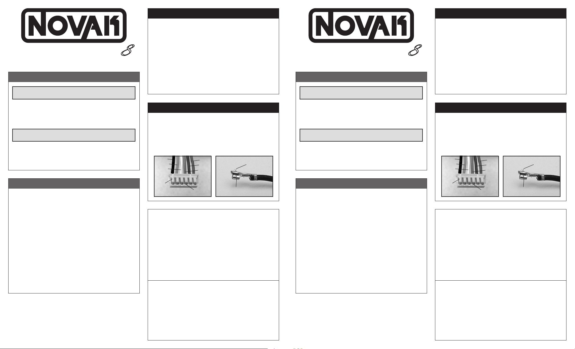
Should any of the small Teflon wires pull out of the motor’s sensor
harness connector, re-insert them in the connector’s appropriate
slot as shown below. There is a small plastic tab that grabs a small
raised barb on the back of the metal socket crimped onto the Teflon
wire’s end. Check the plastic tab to make sure it has not deformed
excessively before inserting the socket into the plastic connector
housing with the barb toward the plastic tabs.
Note: Remove or loosen the bearing cap to remove or insert a sensor harness.
black
orange
white
red
blue
green
raised
metal
barb
BALLISTIC
BRUSHLESS MOTOR INSTRUCTIONS
NEVER FREE-REV THE MOTOR Free-running your brushless
motor in a no-load condition can result in rotor failure and ESC
transistor damage & will void the product’s warranty!
Never free-rev your system to “see how it runs” or you may not get to drive it again!
• WATER & ELECTRONICS DON’T MIX Never allow water, moisture, or
other foreign materials to get inside motor, or on PCBs.
• NOVAK MOTORS & ESCs FOR BEST RESULTS Use Novak sensored
motors with Novak Brushless ESCs for best performance & protection.
use motors with the proper number of turns to match ESC’s rating.
Use of this brushless motor with ESCs that advance motor
timing can result in excessive current draw & severe motor
damage that will NOT be covered by the product’s warranty!
• DO NOT use Ballistic8 motors above 50,000 RPM.
• INSULATE EXPOSED WIRES Use heat shrink tubing to prevent shorts.
• NO SOLVENTS Do NOT expose the motor to any type of solvents.
• SET GEAR MESH PROPERLY Too tight of a gear mesh can result in
motor pinion shaft breakage--be sure to adjust mesh properly.
55-3800-1 Rev. B • 1/2014
8
Only
• CHECK ALL MOTOR SCREWS for loosening at regular intervals, just like
other hardware on your vehicle. Note: The 3 main socket head screws
that hold the motor together may require tightening after a few runs of
the motor. Also check the 3 flat head screws securing the end cap on
the back of the motor--DO NOT OVER-TIGHTEN THESE SCREWS.
• CHECK MOTOR BEARING WEAR after extensive use. The motor’s
closed design will keep most dirt & debris out, but some will get in
and eventually cause wear. If the shaft does not spin freely, you may
need bearing replacement
from Novak)
help extend bearing life--however, too much oil will attract dirt and will
cause problems, so apply sparingly.
• CLEAN INSIDE MOTOR periodically by removing front end cap,
removing the rotor, and blowing out the inside of the motor with
compressed air. Be sure not to lose any small shim washers that may be
on the ends of the rotor shaft & keep them in the correct location.
. A small drop of light oil on the bearings periodically can
(replacement bearing accessory kits are available
Should any of the small Teflon wires pull out of the motor’s sensor
harness connector, re-insert them in the connector’s appropriate
slot as shown below. There is a small plastic tab that grabs a small
raised barb on the back of the metal socket crimped onto the Teflon
wire’s end. Check the plastic tab to make sure it has not deformed
excessively before inserting the socket into the plastic connector
housing with the barb toward the plastic tabs.
Note: Remove or loosen the bearing cap to remove or insert a sensor harness.
black
orange
white
red
blue
green
raised
metal
barb
ACCESSORIES ACCESSORIES
51XX
(5100-5123) 5mm Mod-1 Steel Pinion Gears--9T to 20T--Hardened steel, 5mm bore.
51XX
(5152-5161) 5mm 32-Pitch Steel Pinion Gears--12T to 17T--Hardened steel, 5mm bore.
5351 Brushless Shielded Sensor Harness--4”--Double-ended motor sensor harness.
5352 Brushless Shielded Sensor Harness--6”--Double-ended motor sensor harness.
5353 Brushless Shielded Sensor Harness--9”--Double-ended motor sensor harness.
5508 14GA Brushless Wire Set--2 pieces each of 9” silicone blue, yellow, orange, black & red.
5512 12GA Super-Flex Wire--Black, Red, & Blue--3 ft each color, silicone.
5514 14GA Super-Flex Wire--Black, Red, & Blue--3 ft each color, silicone.
5644 Black Cooling Fan: 40mm x 40mm x 10mm--2-pin JST connector, 5.7CFM @ 5VDC.
5731 3.5mm Power Connectors--5 pair--Gold plated low-loss connectors for 12-14G wire.
5741 4mm Power Connectors--5 pair--Gold plated low-loss high-amp 12-14G connectors.
5832 Lead-Free 3% Silver Racing Solder--15g--Low-resistance, high-conductivity solder.
5850 Heat Shrink Tubing Assortment--6pc--6” long tubing in six sizes from 1/16”-3/8”.
5851 Heat Shrink Tubing Assortment--24pc--6” long tubing in six sizes from 1/16”-3/8”.
5980 Ballistic 8 Sintered Rotor--Replacement 16mm 4-pole Kevlar-wrapped/epoxied rotor.
5981 Ballistic 8L Sintered Rotor--Replacement 16mm 4-pole Kevlar-wrapped/epoxied rotor.
5982 Ballistic 8/8L Front & Rear Flanged Bearing Set--Replacement bearing set.
5983
Ballistic 8/8L Back End Cap/Bearing
5984 Ballistic 8/8L Timing Assembly--Replacement timing & sensor section of Ballistic 8/8L.
5985 Ballistic 8 Outer Sleeve/Heat Sink--Replacement outer sleeve for Ballistic 8.
5986 Ballistic 8L Outer Sleeve/Heat Sink--Replacement outer sleeve for Ballistic 8L.
5987 Ballistic 8/8L Front End Cap/Back Ring--Front end cap (w/bearing) & back end ring.
5988 Ballistic 8 Motor Hardware Set--Replacement screws & shims for Ballistic 8 motor.
5989 Ballistic 8L Motor Hardware Set--Replacement screws & shims for Ballistic 8L motor.
6801 Ballistic 8 Hand-Wound Stator--Y1.5T--Ballistic 8 Wye-wound 1.5-turn stator.
6802 Ballistic 8 Hand-Wound Stator--D2.0T--Ballistic 8 Delta-wound 2.0-turn stator.
--Replacement back end cap w/bearing factory-installed.
Novak Electronics, Inc.
19 Rancho Circle
Lake Forest, CA 92630
(949) 833-8873 • Monday-Thursday
Customer Service e-mail: cs@teamnovak.com
www.tea m n o v a k . c o m
plastic
tabs
metal
barbs
metal socket on end of
Teflon sensor harness wires
SERVICE PROCEDURES
Consider changing out motor parts yourself. All of the Ballistic 8/8L’s main components
are available as service items--Refer to ‘Accessories’ section or check out our web site. In
most cases, replacing motor parts is less expensive than sending in your motor for service.
After reviewing instructions, tech section and how-to video section of website, if you feel
your motor requires service
the most current product service options & pricing by one of the following methods:
WEB: Print out the product SERVICE FORM from CUSTOMER SERVICE section of the web
site. Fill out required information on form & return it with the product requiring service.
PHONE/FAX/E-MAIL: Contact our customer service department by phone, fax, or
e-mail, and we will supply you with current service options.
WARRANTY SERVICE: You MUST CLAIM WARRANTY on product PRODUCT SERVICE FORM &
include a valid cash register receipt with purchase date, dealer name, & phone # on it, or a
previous service invoice. If warranty provisions have been voided, there will be service charges.
ADDITIONAL NOTES:
•
Dealers/distributors are not authorized to replace products thought to be defective.
•
If a hobby dealer returns your product for service, submit a completed product SERVICE
FORM to dealer & make sure it’s included with items.
PRODUCT WARRANTY
Novak Brushless motors are guaranteed to be free from defects in materials or workmanship for a period of 120
days from the original date of purchase (verified by dated, itemized sales receipt). Warranty does not cover incor-
rect installation, components worn by use, cross-connection of battery/motor power wires, overheating solder
tabs, damage resulting from thermal overload or operation above 175°F, use of excessive timing or overheating,
splices or damage to the sensor harness, damage from disassembling motor, tampering with internal electronics,
allowing water, moisture, or any other foreign material to enter motor or get onto the PC board, short-circuiting
of motor by allowing exposed wiring or solder tabs to cross-connect or ESC applying simultaneous power to
more than one phase at a time from switching to Brush Mode, free-revving motor, or any damage caused by
a crash, flooding, or natural disaster. In no case shall our liability exceed the product’s original cost. We reserve
the right to modify warranty provisions without notice.
Because Novak R/C, Inc. has no control over the connection & use of motor or other related electronics, no liability
may be assumed nor will be accepted for damage resulting from the use of this product. Every motor is thoroughly
tested and cycled before leaving our facility and is, therefore, considered operational. This product is not a toy,
and is not intended for use by children under 14 years of age without the strict supervision of an adult. Use of
this product in a uncontrolled manner may result in physical damage or injuries. Take extra care when operating
any remote control vehicle. By the act of connecting/operating speed control, the user accepts all resulting liability.
No part of these instructions may be reproduced without the written permission of Novak R/C, Inc.
©Novak R/C, Inc. California, U.S.A. All Rights Reserved. Novak motors are proudly designed in the U.S.A.
(motor may appear to have failed when other problems exist)
, obtain
51XX
(5100-5123) 5mm Mod-1 Steel Pinion Gears--9T to 20T--Hardened steel, 5mm bore.
51XX
(5152-5161) 5mm 32-Pitch Steel Pinion Gears--12T to 17T--Hardened steel, 5mm bore.
5351 Brushless Shielded Sensor Harness--4”--Double-ended motor sensor harness.
5352 Brushless Shielded Sensor Harness--6”--Double-ended motor sensor harness.
5353 Brushless Shielded Sensor Harness--9”--Double-ended motor sensor harness.
5508 14GA Brushless Wire Set--2 pieces each of 9” silicone blue, yellow, orange, black & red.
5512 12GA Super-Flex Wire--Black, Red, & Blue--3 ft each color, silicone.
5514 14GA Super-Flex Wire--Black, Red, & Blue--3 ft each color, silicone.
5644 Black Cooling Fan: 40mm x 40mm x 10mm--2-pin JST connector, 5.7CFM @ 5VDC.
5731 3.5mm Power Connectors--5 pair--Gold plated low-loss connectors for 12-14G wire.
5741 4mm Power Connectors--5 pair--Gold plated low-loss high-amp 12-14G connectors.
5832 Lead-Free 3% Silver Racing Solder--15g--Low-resistance, high-conductivity solder.
5850 Heat Shrink Tubing Assortment--6pc--6” long tubing in six sizes from 1/16”-3/8”.
5851 Heat Shrink Tubing Assortment--24pc--6” long tubing in six sizes from 1/16”-3/8”.
5980 Ballistic 8 Sintered Rotor--Replacement 16mm 4-pole Kevlar-wrapped/epoxied rotor.
5981 Ballistic 8L Sintered Rotor--Replacement 16mm 4-pole Kevlar-wrapped/epoxied rotor.
5982 Ballistic 8/8L Front & Rear Flanged Bearing Set--Replacement bearing set.
5983
Ballistic 8/8L Back End Cap/Bearing
5984 Ballistic 8/8L Timing Assembly--Replacement timing & sensor section of Ballistic 8/8L.
5985 Ballistic 8 Outer Sleeve/Heat Sink--Replacement outer sleeve for Ballistic 8.
5986 Ballistic 8L Outer Sleeve/Heat Sink--Replacement outer sleeve for Ballistic 8L.
5987 Ballistic 8/8L Front End Cap/Back Ring--Front end cap (w/bearing) & back end ring.
5988 Ballistic 8 Motor Hardware Set--Replacement screws & shims for Ballistic 8 motor.
5989 Ballistic 8L Motor Hardware Set--Replacement screws & shims for Ballistic 8L motor.
6801 Ballistic 8 Hand-Wound Stator--Y1.5T--Ballistic 8 Wye-wound 1.5-turn stator.
6802 Ballistic 8 Hand-Wound Stator--D2.0T--Ballistic 8 Delta-wound 2.0-turn stator.
Novak Electronics, Inc.
Lake Forest, CA 92630
(949) 833-8873 • Monday-Thursday
Customer Service e-mail: cs@teamnovak.com
www.tea m n o v a k . c o m
--Replacement back end cap w/bearing factory-installed.
19 Rancho Circle
plastic
tabs
metal
barbs
metal socket on end of
Teflon sensor harness wires
SERVICE PROCEDURES
Consider changing out motor parts yourself. All of the Ballistic 8/8L’s main components
are available as service items--Refer to ‘Accessories’ section or check out our web site. In
most cases, replacing motor parts is less expensive than sending in your motor for service.
After reviewing instructions, tech section and how-to video section of website, if you feel
your motor requires service
the most current product service options & pricing by one of the following methods:
WEB: Print out the product SERVICE FORM from CUSTOMER SERVICE section of the web
site. Fill out required information on form & return it with the product requiring service.
PHONE/FAX/E-MAIL: Contact our customer service department by phone, fax, or
e-mail, and we will supply you with current service options.
WARRANTY SERVICE: You MUST CLAIM WARRANTY on product PRODUCT SERVICE FORM &
include a valid cash register receipt with purchase date, dealer name, & phone # on it, or a
previous service invoice. If warranty provisions have been voided, there will be service charges.
ADDITIONAL NOTES:
•
Dealers/distributors are not authorized to replace products thought to be defective.
•
If a hobby dealer returns your product for service, submit a completed product SERVICE
FORM to dealer & make sure it’s included with items.
PRODUCT WARRANTY
Novak Brushless motors are guaranteed to be free from defects in materials or workmanship for a period of 120
days from the original date of purchase (verified by dated, itemized sales receipt). Warranty does not cover incor-
rect installation, components worn by use, cross-connection of battery/motor power wires, overheating solder
tabs, damage resulting from thermal overload or operation above 175°F, use of excessive timing or overheating,
splices or damage to the sensor harness, damage from disassembling motor, tampering with internal electronics,
allowing water, moisture, or any other foreign material to enter motor or get onto the PC board, short-circuiting
of motor by allowing exposed wiring or solder tabs to cross-connect or ESC applying simultaneous power to
more than one phase at a time from switching to Brush Mode, free-revving motor, or any damage caused by
a crash, flooding, or natural disaster. In no case shall our liability exceed the product’s original cost. We reserve
the right to modify warranty provisions without notice.
Because Novak R/C, Inc. has no control over the connection & use of motor or other related electronics, no liability
may be assumed nor will be accepted for damage resulting from the use of this product. Every motor is thoroughly
tested and cycled before leaving our facility and is, therefore, considered operational. This product is not a toy,
and is not intended for use by children under 14 years of age without the strict supervision of an adult. Use of
this product in a uncontrolled manner may result in physical damage or injuries. Take extra care when operating
any remote control vehicle. By the act of connecting/operating speed control, the user accepts all resulting liability.
No part of these instructions may be reproduced without the written permission of Novak R/C, Inc.
©Novak R/C, Inc. California, U.S.A. All Rights Reserved. Novak motors are proudly designed in the U.S.A.
(motor may appear to have failed when other problems exist)
, obtain
Page 2
INSTALLATION INSTRUCTIONS INSTALLATION INSTRUCTIONS
1. NO MOTOR CAPACITORS & SCHOTTKY NEEDED
Novak brushless motors do not need motor capacitors or external
Schottky diodes--
2. CHECK MOTOR SCREW LENGTH & INSTALL MOTOR
•
Insert the motor mounting screws that came with your vehicle
through the motor mounting plate. Ballistic8 motors need no
more than about 3/16” of screw extending past the vehicle’s
Schottky diode usage will damage ESC
.
TIMING WARNING (Important
Due to the nature of timing advance speed controls, motor tolerances & settings, vehicle
performance, and track conditions, it has become virtually impossible to provide installation and operation recommendations that will allow you to use these speed controls and
motors at their highest performance levels without the potential for unwanted damage.
You must, use extreme caution when setting up these electronics and carefully test your
application to avoid overloading and overheating either the speed control or the motor.
These are racing electronics used in racing conditions, and therefore damage as the
result of excessive overheating will not be covered under the product’s factory warranty.
mounting plate (4-5mm)--Too little can strip the motor’s threads,
too much will cause internal motor damage & will void warranty.
• Attach motor to vehicle’s motor mount using one of the sets of
threaded mounting holes--select a mounting position that keeps the
solder tabs clear of conductive surfaces like aluminum or graphite.
3.
INSTALL PINION GEAR (see GEAR SELECTION)
Install pinion on motor and test fit in vehicle to align pinion and
spur gears. Tighten pinion’s set screw on the flat of motor shaft.
4. ADJUST MOTOR FOR PROPER GEAR MESH
•
Adjust the motor position for proper amount of free play. You
NEED to have a small amount of play between the pinion gear
and the spur gear
(about the thickness of piece of paper)--check
the free play at several positions around the spur gear to
ensure a proper mesh
MAKE SURE THE PINION/SPUR GEAR MESH IS NOT TOO TIGHT!
(just in case the gears are out of round).
If gear mesh is too tight, motor shaft breakage can occur.
• Tighten motor mounting screws--Avoid using excessive force,
as the threaded holes in motor could become stripped.
5. SOLDER MOTOR POWER WIRES
(skip this step if motor is wired to ESC)
• Determine the best routing in vehicle for the motor’s silicone
power wires--avoid any moving parts & suspension.
GEAR SELECTION (Important
Motor operating temperature is the ONLY
way to properly set the maximum vehicle gearing
The motor should be 160-175°F MAX at end of run!
Temperatures above 175°F will weaken the magnet & may
melt the coils! This voids warranty & can damage ESC!
Change the gearing to avoid overheating.
Because of potential ESC/Motor overheating, damage, & failure, you must start
with VERY small pinion sizes and check ESC & motor temperatures multiple
times during initial runs to ensure that you are not causing excessive heating.
If ESC/Motor temperatures remain low & stable, you can slowly increase the pinion size
while again monitoring the temperatures to determine safe gearing for your vehicle,
motor, & track conditions. Because these variables can change, you MUST continually
monitor ESC & motor temperatures to protect your electronics from damage.
Because of the broad power band of brushless, you can go 1-2 teeth higher
pinion than the above recommendations for more top speed, but remember any
See our website or contact us for additional gearing information & recommendations.
higher will produce excessive ESC & motor heating.
• Prepare ends of power wires by stripping 3/16-1/4” of
insulation from end of wire. Tin wire ends with solder.
• Lay tinned end of the wire flat on the proper solder tab
(refer to phase markings on end ring above solder tabs)
and solder
wires to the motor. Apply heat with a high-power soldering
iron to the power wire and solder tab--begin adding solder to
tip of iron and to wire--Add just enough solder to form a clean
& continuous joint from the solder tab up onto the wire.
WARNING: Be sure no phase wires make contact with an adjacent solder
tab--this will cause short-circuiting, damage electronics, & void warranty.
IMPORTANT NOTE: DO NOT OVERHEAT SOLDER TABS
Prolonged/excessive heating will damage tabs & void the warranty.
6. CONNECT MOTOR SENSOR HARNESS
• Determine the best routing in vehicle for the motor’s sensor
harness--securing sensor harness to the motor power wires with a
tie-wrap can provide a good location & also act as a strain relief.
• Connect one end of sensor harness to ESC & the other end
to the motor’s sensor harness connector located under the
back bearing cover--remove two flat head screws to remove
cover to access connector. Be sure the plug on the ends of the
harness insert all the way into the sensor harness connectors--the
plug & connector are keyed and will only go together one direction.
MOTOR TIMING ADJUSTMENT MOTOR TIMING ADJUSTMENT
The Ballistic 8/8L motor’s timing is adjustable by simply loosening the three M2.5
flat head screws on the back bearing cap, rotating the bearing cap to desired setting,
and then re-tightening the screws.
The motor’s factory timing is marked with a timing label located on the side of the
back bearing cap and lines up with a groove milled into the top of the back end ring.
Novak motors are factory timed to the most efficient setting for their given wind.
Note: Wye-wound motors are timed to the “Y” mark on the motor’s timing
label and Delta-wound motors are timed to the “D” mark on the label. When
replacing a stator with a different wind type (Wye/Delta) rotate the end cap to
line up with the appropriate wind type for proper motor operation.
Advancing the timing will increase the motor’s RPM range & reduce its torque, but
will also make the motor less efficient and it will in turn pull more current, resulting
in higher speed control & motor operating temperatures.
Adjusting the timing more than 2 timing marks on the timing label
will result in dangerously high current draw and heating that can lead
to ESC & motor failure, and will void the product’s warranty.
Retarding the timing will reduce the motor’s RPM range & increase its torque--this
also usually reduces current draw and lowers operating temperatures. For each timing mark (on label) reduced, you should increase the pinion gear size by one tooth
to accommodate for the lower RPM range.
)
1. NO MOTOR CAPACITORS & SCHOTTKY NEEDED
Novak brushless motors do not need motor capacitors or external
Schottky diodes--
2. CHECK MOTOR SCREW LENGTH & INSTALL MOTOR
•
Insert the motor mounting screws that came with your vehicle
through the motor mounting plate. Ballistic8 motors need no
more than about 3/16” of screw extending past the vehicle’s
mounting plate (4-5mm)--Too little can strip the motor’s threads,
too much will cause internal motor damage & will void warranty.
)
• Attach motor to vehicle’s motor mount using one of the sets of
threaded mounting holes--select a mounting position that keeps the
solder tabs clear of conductive surfaces like aluminum or graphite.
3.
INSTALL PINION GEAR (see GEAR SELECTION)
Install pinion on motor and test fit in vehicle to align pinion and
spur gears. Tighten pinion’s set screw on the flat of motor shaft.
4. ADJUST MOTOR FOR PROPER GEAR MESH
•
Adjust the motor position for proper amount of free play. You
NEED to have a small amount of play between the pinion gear
and the spur gear
the free play at several positions around the spur gear to
ensure a proper mesh
MAKE SURE THE PINION/SPUR GEAR MESH IS NOT TOO TIGHT!
If gear mesh is too tight, motor shaft breakage can occur.
• Tighten motor mounting screws--Avoid using excessive force,
as the threaded holes in motor could become stripped.
5. SOLDER MOTOR POWER WIRES
• Determine the best routing in vehicle for the motor’s silicone
power wires--avoid any moving parts & suspension.
• Prepare ends of power wires by stripping 3/16-1/4” of
insulation from end of wire. Tin wire ends with solder.
• Lay tinned end of the wire flat on the proper solder tab
(refer to phase markings on end ring above solder tabs)
wires to the motor. Apply heat with a high-power soldering
iron to the power wire and solder tab--begin adding solder to
tip of iron and to wire--Add just enough solder to form a clean
& continuous joint from the solder tab up onto the wire.
WARNING: Be sure no phase wires make contact with an adjacent solder
tab--this will cause short-circuiting, damage electronics, & void warranty.
IMPORTANT NOTE: DO NOT OVERHEAT SOLDER TABS
Prolonged/excessive heating will damage tabs & void the warranty.
6. CONNECT MOTOR SENSOR HARNESS
• Determine the best routing in vehicle for the motor’s sensor
harness--securing sensor harness to the motor power wires with a
tie-wrap can provide a good location & also act as a strain relief.
• Connect one end of sensor harness to ESC & the other end
to the motor’s sensor harness connector located under the
back bearing cover--remove two flat head screws to remove
cover to access connector. Be sure the plug on the ends of the
harness insert all the way into the sensor harness connectors--the
plug & connector are keyed and will only go together one direction.
Schottky diode usage will damage ESC
(about the thickness of piece of paper)--check
(just in case the gears are out of round).
(skip this step if motor is wired to ESC)
and solder
ww w.t eam nov ak .c om ww w.t eam nov ak .c om
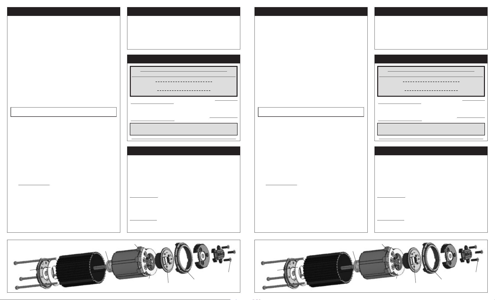
BALLISTIC 8/8L MOTOR
Exploded View
4-40 socket
head cap screws
fiberglass
front insulator
front end cap front end cap
drill balanced
Kevlar-wrapped
4-pole rotor
outer sleeve/heat sink outer sleeve/heat sink
low-loss solder tabs low-loss solder tabs
epoxy-dipped
hand-wound
12 slot stator
fiberglass
stamping
insulators
timing
assembly
sensor harness
connector
bearing
bearing
back
end ring
available replacement components.
cap
timing groove timing groove
Refer to ‘Accessories’ section for
cover
M2.5x10mm
flat head
cap screws
BALLISTIC 8/8L MOTOR
Exploded View
4-40 socket
head cap screws
fiberglass
front insulator
drill balanced
Kevlar-wrapped
4-pole rotor
.
epoxy-dipped
hand-wound
12 slot stator
TIMING WARNING (Important
Due to the nature of timing advance speed controls, motor tolerances & settings, vehicle
performance, and track conditions, it has become virtually impossible to provide installation and operation recommendations that will allow you to use these speed controls and
motors at their highest performance levels without the potential for unwanted damage.
You must, use extreme caution when setting up these electronics and carefully test your
application to avoid overloading and overheating either the speed control or the motor.
These are racing electronics used in racing conditions, and therefore damage as the
result of excessive overheating will not be covered under the product’s factory warranty.
GEAR SELECTION (Important
)
)
Motor operating temperature is the ONLY
way to properly set the maximum vehicle gearing
The motor should be 160-175°F MAX at end of run!
Temperatures above 175°F will weaken the magnet & may
melt the coils! This voids warranty & can damage ESC!
Change the gearing to avoid overheating.
Because of potential ESC/Motor overheating, damage, & failure, you must start
with VERY small pinion sizes and check ESC & motor temperatures multiple
times during initial runs to ensure that you are not causing excessive heating.
If ESC/Motor temperatures remain low & stable, you can slowly increase the pinion size
while again monitoring the temperatures to determine safe gearing for your vehicle,
motor, & track conditions. Because these variables can change, you MUST continually
monitor ESC & motor temperatures to protect your electronics from damage.
Because of the broad power band of brushless, you can go 1-2 teeth higher
pinion than the above recommendations for more top speed, but remember any
See our website or contact us for additional gearing information & recommendations.
The Ballistic 8/8L motor’s timing is adjustable by simply loosening the three M2.5
flat head screws on the back bearing cap, rotating the bearing cap to desired setting,
and then re-tightening the screws.
The motor’s factory timing is marked with a timing label located on the side of the
back bearing cap and lines up with a groove milled into the top of the back end ring.
Novak motors are factory timed to the most efficient setting for their given wind.
Note: Wye-wound motors are timed to the “Y” mark on the motor’s timing
label and Delta-wound motors are timed to the “D” mark on the label. When
replacing a stator with a different wind type (Wye/Delta) rotate the end cap to
line up with the appropriate wind type for proper motor operation.
Advancing the timing will increase the motor’s RPM range & reduce its torque, but
will also make the motor less efficient and it will in turn pull more current, resulting
in higher speed control & motor operating temperatures.
Adjusting the timing more than 2 timing marks on the timing label
will result in dangerously high current draw and heating that can lead
Retarding the timing will reduce the motor’s RPM range & increase its torque--this
also usually reduces current draw and lowers operating temperatures. For each timing mark (on label) reduced, you should increase the pinion gear size by one tooth
to accommodate for the lower RPM range.
higher will produce excessive ESC & motor heating.
to ESC & motor failure, and will void the product’s warranty.
timing
assembly
bearing
cover
M2.5x10mm
flat head
cap screws
fiberglass
stamping
insulators
sensor harness
connector
bearing
back
end ring
available replacement components.
cap
Refer to ‘Accessories’ section for
 Loading...