

Novak Atom ESC User Manual

OPERATING INSTRUCTIONS
The ATOM
SPECIFICATIONS
Part #1770
STEP 1
CHANGING THE INPUT PLUG
The Atom ESC comes with the industry
harness connector. This connector works
radio brands. However, with some older style
sequence of the wires in the plastic connector
needs to be changed. This is an important step,
the electronics inside the receiver may be damaged
wiring sequence is incorrect. Changing the sequence is
easily accomplished as described below.
standard input
with all major
receivers the
housing
because
if the
JR • Hitec • Futaba • New KO • Airtronics Z
If your receiver is a JR, Hitec, Futaba, new KO, or an
Airtronics Z
the ESC's input harness wires. The new Airtronics Z receiver
has a blue colored plastic case. The new KO cases have
tabs on the input harness openings as shown in Figure 1.
• Insert the input plug into the receiver with the BLACK
wire toward the outside edge of the receiver case.
tabs
New KO (with tabs) Old KO (no tabs)
you do not need to change the sequence of
FIGURE 1 FIGURE 2
no tabs
black
wires
red
wires
Old-style KO • Old-style Sanwa/Airtronics
If your receiver is an older KO or Sanwa/Airtronics, you
must change the sequence of the ESC's input harness
wires. Old Sanwa/Airtronics cases are black in color. Old
KO cases do not have the tab openings (See Figure 2).
• Interchange the red and black wires in the plug plastic
of the ESC's input harness as shown in Figure 3 below.
• Insert the input plug into the receiver with the RED
wire toward the outside edge of the receiver case.
FIGURE 3 With a small standard screwdriver, gently lift
the plastic prong until the wire and metal socket easily
slides out of the plastic housing. Repeat for each wire.
STEP 2
MOUNTING INSTRUCTIONS
1.
DETERMINE BEST ESC MOUNTING LOCATION
Speed control should be positioned away from the
receiver and antenna as shown in set-up photo (back page).
Choose a mounting position that will keep power wires
away from the receiver and antenna. Choose position
that will provide maximum airflow through transistor
tabs or heat sinks to allow for proper cooling.
2. INSTALL THE SPEED CONTROL
Use the included double-sided tape to mount ESC.
3. INSTALL THE ON/OFF SWITCH
Determine a convenient place to mount the switch
where it will be easy to get to. Mount switch using a
piece of double-sided tape or with a screw through
the hole in the base of the switch housing.
4. INSTALL THE RECEIVER AND ANTENNA
Mount receiver as far from ESC, motor, power wires,
battery, and servo as possible. These components all
emit radio noise when the throttle is being applied.
On graphite or aluminum, it may help to place the
receiver on edge with the crystal and antenna as far
above the
to the receiver
the antenna mast.
Cutting or coiling excess wire will reduce radio range.
chassis as possible. Mount the antenna close
and trail any excess wire off the top of
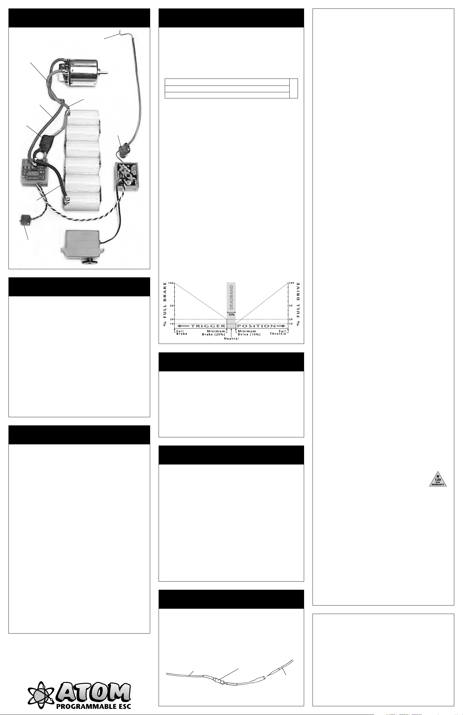
The Novak Atom is an all-digital, microprocessor-based
ESC
(Electronic Speed Control)
components and the best HYPERFET III transistors to deliver
the highest performance with the smallest size and lightest
weight. The Atom has 3
the ability to store a 4th custom profile created by the
software in the Millennium Pro (#4490) or Pit Wizard (#1035/
older Pit Wizards requires adaptor #5710)
Novak’s Constant Force Braking provides more effective
braking at lower motor RPMs, while a minimum brake
adjustment pot lets you set initial braking from 0-75%.
Low-resistance solder posts and Super-Flex™ wire give
minimal voltage drop and high current handling, while
allowing quick and easy wire replacement and positioning.
Novak’s Polar Drive Circuitry gives you increased power
and reduced operating temperatures. This means even
smoother throttle response, increased radio system range,
quicker acceleration, and longer run times.
Other features include the original One-Touch Set-Up™,
exclusive Radio Priority Circuitry™, Digital Anti-Glitch
Circuitry™, the Novak Input Plug System™, a heavy-duty
BEC to handle high power racing servos, and trouble free
low-voltage operation down to 2 volts.
that uses advanced micro-
user-selectable throttle
, for extreme flexibility.
profiles and
PRECAUTIONS
• WATER & ELECTRONICS DON’T MIX! Do not operate
model in or around water. Never allow water, moisture, or
other foreign materials to get inside the ESC.
• 4 to 6 CELLS ONLY Never use more than 6 cells (7.2 volts
DC) in the main battery pack.
•
MOTOR CAPACITORS REQUIRED Three 0.1µF (50V) ceramic
capacitors must be properly installed on every motor to
prevent radio interference.
•
SCHOTTKY DIODE & POWER CAPACITOR REQUIRED An
external Schottky diode
because the Atom does not have internal ones.
without these components can damage ESC and will void warranty.
•
NO REVERSE VOLTAGE! Reverse battery polarity can damage
speed control––Disconnect battery immediately.
• DON’T LET TRANSISTOR TABS TOUCH Never allow the
two transistor tab banks to touch each other or any
metal. The short circuit will
•
DISCONNECT THE BATTERIES Always disconnect the battery
pack from the speed control when not in use.
• TRANSMITTER ON FIRST Always turn on the power of
your transmitter first so that you will have control of the
radio equipment when you turn on the speed control.
•
DON’T GET BURNT! Transistor tabs can get hot, so be careful.
If transistor tabs get
• INSULATE WIRES Always insulate exposed wiring with heat
shrink tubing to prevent short circuits.
STEP 3
HOOK-UP INSTRUCTIONS
1. INSTALL MOTOR CAPACITORS
Electric motors generate radio noise that causes radio
interference. Included are three 0.1 µF (50V) non-polarized
ceramic capacitors. These capacitors must be installed on
every motor to help reduce the noise generated by the motor
and also to prevent possible damage to the speed control.
Note: Some motors come with capacitors built-in, and you may
only need to install the capacitor between the positive & negative
motor tabs if the motor comes with only two capacitors.
Solder 0.1µF (50V) capacitors between:
• POSITIVE (+) motor tab & NEGATIVE (–) motor tab.
• POSITIVE (+) motor tab & GROUND tab*.
• NEGATIVE (–) motor tab & GROUND tab*.
*If motor has no ground tab, solder the capacitors to motor can.
Extra 0.1µF capacitors are available in Novak kit #5620.
2. INSTALL SCHOTTKY DIODE
Solder the lead CLOSEST to the silver stripe on the body of
the Schottky diode to the POSITIVE (+) motor tab.
Solder the lead OPPOSITE the silver stripe on the body of
the Schottky to the NEGATIVE (–) motor tab.
If installed backwards, a Schottky diode will be destroyed. The
body of a bad diode will normally crack open. Replace only with
Schottky diodes that have a minimum rating of 35 volts / 8 amps.
Schottky diodes are available in Novak kit #5640.
3. INSTALL POWER CAPACITOR
The included power capacitor will drop the speed control’s
operating temperatures by 10-15°F, and will help dissipate noise
and voltage spikes from the ESC’s high switching speed.
To allow greater flexibility for your application, you can
install the power capacitor up against the side or back of
the Atom, or heat shrink it along the power wires.
To install capacitor alongside the Atom:
Use included double-sided tape to hold the capacitor
against the side or back of the Atom’s case.
Bend negative lead (–) {shorter/marked with stripe} toward the
BLK solder post. Insulate lead with included vinyl tubing.
Solder negative lead
Bend positive lead (+) {longer/unmarked} toward the RED
solder post. Insulate lead with included vinyl tubing.
Solder positive lead
and power capacitor must be used
damage the ESC.
extremely hot use optional heat sinks.
Refer to Set-Up photo on back
Negative (–) motor tab
0.1µF Capacitors
Schottky diode
Positive (+) motor tab
Ground / motor can
(–)
to the BLK solder post.
(+)
to the RED solder post.
negative lead (–)
with stripe
Insulate leads
with vinyl tubing
Atom usage
exposed
Input Voltage 4-6 cells (1.2 volts DC/cell)
Case Width 1.23 inches [3.12 cm]
Case Depth 1.16 inches [2.95 cm]
Case Height 0.69 inch [1.75 cm]
Weight (w/o heat sinks) 1.00 ounce [28.4 g]
On-Resistance
Rated Current 240 amps
Braking Current 80 amps
BEC Voltage / Current 6.0 volts DC / 3.0 amps
Power Wire (Battery/Motor)
Signal Harness Length 8 inches [20.3 cm]
Minimum Brake Range 0 to 75 % Full Brake
Minimum Drive
Deadband (% Full Throttle) (1) 6.0 (2) 6.0 (3) 4.0
Drive Frequency (kHz) (1) 5.86 (2) 7.80
Brake Frequency (kHz) (1) 3.90 (2) 5.86
@ Transistors 0.0013 Ω
9“
Super-Flex
(% Full Drive)
(1) 6.0 (2) 6.0 (3) 1.5
@ 25°C transistor
junction temp.
[22.8 cm]
(3) 15.6
(3) 3.90
ACCESSORIES
MOTOR CAPACITORS
To prevent radio interference, you must have three 0.1µF
capacitors properly installed on every motor. Three 0.1µF
(50v) capacitors are included for one motor. Additional
0.1µF (50V) capacitors are available in Novak kit #5620.
Refer to Step 3 for motor capacitor installation instructions.
SCHOTTKY DIODES
The Atom does not have an internal Schottky diode.
External Schottky diodes are included, and must be used
for optimum braking, motor, and speed control performance. Refer to Step 3 for installation instructions.
Additional Schottky diodes are available in Novak kit #5640.
HEAT SINKS
Heat sinks are not required with the Atom. However,
added cooling from heat sinks can increase
An optional Heat Sink Set is
Heat sinks are recommended
and set-ups with limited air
get excessively hot during
available as Novak kit #5411.
for heavy load applications
circulation, or if the transistors
operation.
efficiency.
POWER CAPACITORS
An external power capacitor is included, and must be
used to maintain cool and smooth operation.
Refer to Step 3 for installation instructions.
Additional Power Capacitors are available in Novak kit #5670.
STEP 3
HOOK-UP INSTRUCTIONS (Cont.)
To install capacitor along the Atom’s power wires:
,
Install capacitor as close to the speed control as possible.
Make a small splice on the black and red power wires.
Solder the negative lead (–) to the splice on the black wire.
Solder the positive lead (+) to the splice on the red wire.
Secure power capacitor to power wires with included
large heat shrink to insulate and protect from vibration.
4. CONNECT SPEED CONTROL TO THE RECEIVER
After the proper input plug plastic has been installed
to match the receiver (Refer to Step 1), plug the speed
control into the
5. CONNECT SPEED CONTROL TO THE BATTERY PACK
Cut the BLACK wire to the desired length and strip
about 1/8”-1/4” of insulation off each end. Solder to
the negative side of a completely charged 4 to 6 cell
battery pack and the other end to the BLK solder post.
Cut the
battery positive to motor) and strip about 1/8”-1/4” of
insulation off each end. Strip a short section of insulation
(1/4”-3/8”) from the middle section of the RED wire
where it will attach to positive of battery pack. Solder
the stripped section of
pack and one end to the RED solder post.
NOTE:
result in the post desoldering from PCB and short-circuiting.
6. CONNECT SPEED CONTROL TO THE MOTOR
Solder the free end of the
Cut the BLUE wire to desired length and strip about
1/8”-1/4” of insulation off each end. Solder to the
negative tab of the motor and to the BLUE solder post.
TIP: Twisting the BLUE & RED motor wires one or two times
around each other as they go to motor can help reduce any
radio noise that may be emitted from the power wires.
7.
USING PLUGS FOR BATTERY & MOTOR CONNECTION
High-quality/low-resistance connector plugs, such as
Dean’s Ultra Plugs, can also be used to connect the
motor and battery pack. While connectors make component changes quick and easy, they
the low resistance of a good solder joint.
Use connectors that can not be connected backwards.
It is good practice to use female connectors on batteries
to avoid shorting the connector and the battery.
If you use connectors for the battery and the motor,
use a male connector on the ESC wires going to the
battery and a female connector on the wires going to
the motor. By doing this, you will avoid plugging the
battery into the motor output of the ESC by mistake.
RED wire to desired length (to go from ESC to
Prolonged or excessive heating of solder post can
THROTTLE CHANNEL of the receiver.
RED wire to positive of battery
RED
wire to positive motor tab.
will never have
SET-UP PHOTO
Trail excess wire
off antenna mast.
(Do not cut or coil)
Tip: Twist motor
wires to reduce
radio noise!
Blue wire
(motor negative)
Power Capacitor
Black wire
(battery negative)
Mount switch
where it will be
easy to get to.
(–)
(+)
Red wire
(battery & motor positive)
(+)
(–)
Keep receiver and
antenna away
from motor,
servo, battery,
and power wires.
STEP 6
THROTTLE PROFILE SELECTION
The Atom allows you to choose between three user-selectable
throttle profiles that are programmed at the factory. This chart
gives the specifics of each profile:
Brake Frequency
Profile
1 Stock 6.0 5.86 6.0 3.90 OFF
2 Drag Brake 6.0 7.80 6.0 5.86 ON
3
Experiment with each profile to determine which works best for you!
1. TURN ON THE TRANSMITTER
2. TURN ON THE SPEED CONTROL
3. PRESS & HOLD ESC’S 1-TOUCH BUTTON until the status
LED turns solid green. The LED will first turn red, then a
few seconds later it will turn green.
4. RELEASE 1-TOUCH BUTTON and then the status LED will
begin to blink red. The number of times the LED blinks
indicates the profile number selected.
PRESS & RELEASE 1-TOUCH BUTTON TO SELECT PROFILE
5.
Each press will change to the next consecutive profile number.
NOTE: After profile #3, the sequence begins again at profile #1.
6. If 1-TOUCH button is not pushed for about five seconds,
the ESC LOADS THE SELECTED PROFILE INTO MEMORY,
and the status LED turns solid red, indicating that the speed
control has exited the profile selection mode and is in neutral.
The Atom can store a custom 4th profile that is created with the
optional software in the Millennium Pro (#4490) & the Pit Wizard
(#1035). Once a custom profile has been created and downloaded into the ESC, there will be four profiles to choose from.
Both programming devices come with complete details on creating
your own custom profiles and give you the ability to modify the
following parameters: Neutral, Full Throttle, & Full Brake Positions
Dead Band Value, Drag Brake Value, Drag Brake Frequency*, Drive
PWM Frequency*, Minimum Drive Value, Brake PWM Frequency*,
and Drag Brake Toggle. *Adjustable from 122-23,400 Hz
Illustration below shows graphical display of adjustable parameters
Description
**Modified 4.0 15.60 1.5 3.90 OFF
Dead Band
(**default)
% kHz % kHz
Minimum Drive
Drive Frequency
Dr.Brake Toggle
ATOM
,
TROUBLE-SHOOTING GUIDE
This section describes possible speed control problems,
causes, and solutions.
Steering Channel Works But Motor Will Not Run
• Speed control has thermally shut down––Allow ESC to
cool down––Use milder motor or smaller pinion gear.
• Check motor connections. Check motor and brushes.
• Make sure ESC is plugged into the throttle channel of
receiver. Check throttle channel operation with a servo.
Check wiring color sequence of receiver signal harness.
• Possible internal damage––Refer to Service Procedures.
Receiver Glitches/Throttle Stutters During Acceleration
• Motor capacitors broken or missing––Refer to Step 3.
• Receiver or antenna too close to speed control, power
wires, battery, or motor––Refer to Step 2.
• Bad connections––Check wiring and connectors.
• Motor brushes worn––Replace brushes.
• Excessive current to motor––Use a milder motor or a
smaller pinion gear.
Motor and Steering Servo Do Not Work
• Check wires, receiver signal harness wiring and color
sequence, radio system, crystals, battery and motor connectors, and battery pack.
• Possible internal damage––Refer to Service Procedures.
Model Runs Slowly / Slow Acceleration
•
Check motor and battery connectors––Replace if needed.
• Bad battery or motor––Check operation with another.
• Incorrect transmitter or speed control adjustment––
Refer to Steps 4 and 5.
• Optional external Schottky diode installed backwards
or damaged––Refer to Step 3.
Motor Runs Backwards
• Motor wired backwards––Check wiring and reverse.
• Backwards motor timing––Reverse motor end bell.
ESC Is Melted Or Burnt/ESC Runs With Switch Off
• Internal damage––Refer to Service Procedures.
*For more help call our Customer Service Department.
STEP 4
TRANSMITTER ADJUSTMENTS
For proper ESC operation adjust transmitter as follows:
1. Set HIGH ATV or EPA to maximum setting.
[Controls amount of throw from neutral to full throttle]
2. Set LOW ATV, EPA, or ATL to maximum setting.
[Controls amount of throw from neutral to full brakes]
[Reduce this after programming to reduce amount of brakes]
3. Set EXPONENTIAL to zero.
[Controls the linearity of the throttle channel]
4. Set THROTTLE CHANNEL TRIM to middle setting.
[Adjusts neutral position/Increases or decreases coast brakes]
5.
Set CHANNEL REVERSING SWITCH to either position.
6. Set ELECTRONIC TRIGGER THROW ADJUSTMENT
to 70% throttle and 30% brake throw (or 7:3).
[Adjusts pistol-grip transmitter’s throttle trigger throw]
7. Set MECHANICAL TRIGGER THROW ADJUSTMENT
to position with 2/3 throttle and 1/3 brake throw.
[Adjusts pistol-grip transmitter’s throttle trigger throw]
STEP 5
SPEED CONTROL PROGRAMMING
Before beginning this step, the speed control should be
connected to the receiver and to a charged 4 to 6 cell
battery pack, and the transmitter should be adjusted.
1. CONNECT THE BATTERY
2.
TURN ON TRANSMITTER THEN THE SPEED CONTROL
Slide the ON/OFF switch to the ON position.
3. PRESS AND HOLD ESC’S 1-TOUCH BUTTON
With the transmitter throttle in the neutral position,
press and hold the
until the status LED turns solid red.
4. RELEASE ESC’S 1-TOUCH BUTTON
5. PULL THROTTLE TO FULL-FORWARD POSITION
Hold it there until the status
NOTE: The motor will not run during programming even
if it is connected to the speed control.
6. PUSH THROTTLE TO FULL-BRAKE POSITION
Hold it there until the status
7. RETURN TRANSMITTER THROTTLE TO NEUTRAL
The status
LED will turn solid red, indicating that the
throttle is in the neutral position and also that proper
programming has been completed.
The speed control is programmed and ready to race!
If transmitter settings are changed, it will be necessary
to complete the programming sequence once again.
If you experience any problems during programming,
turn off the speed control and repeat programming.
NOVAK ELECTRONICS, INC.
18910 Teller Avenue
Irvine, CA 92612
www.teamnovak.com
SET button on the speed control
LED turns solid green.
LED blinks green.
STEP 7
MINIMUM BRAKE ADJUSTMENT
The BRAKE pot on the Atom speed control allows you to adjust
the percentage of total braking power applied with the initial
trigger movement in the brake direction. Refer to the illustration
above for indication of Minimum Brake Value.
Note: In profile 2 the Atom’s pot adjusts the amount of drag brake.
•
Turning BRAKE pot clockwise, increases amount of minimum
braking up to a maximum of 75% of the total brake force.
• Turning BRAKE pot all the way counter-clockwise, sets the
amount of minimum braking at the lowest value of 0.39%,
or 1/256th (one step) of the total brake force.
RECEIVER BATTERY PACK
The Atom speed control should not require an external
receiver battery pack for most racing situations.
Radio-Priority Circuity™ provides complete control of the
steering servos even after the main battery pack has ‘dumped’
and can no longer provide the power required to turn the
motor. However, applications with multiple high-power servos,
and some 4-cell set-ups may require an external receiver battery
pack to prevent overloading or underpowering of the speed
control’s voltage regulator.
1. Plug the external 5 cell nickel cadmium receiver battery
pack into the battery slot of the receiver.
Leave the speed control’s ON/OFF switch in the OFF position
2.
This switch is not used with this configuration.
3. Use the ON/OFF switch on the external receiver battery
pack to turn the system power on and off.
Note: If using a FET servo with an external receiver battery pack, the
separate power wire from the servo must be connected to the red or
positive servo wire. For this application do not use blue wire from ESC.
The built-in
.
FET SERVO CONNECTION
The Atom speed control is wired for connecting a FET servo
that requires seperate power connection. The fourth wire from
the servo is connected to the small blue 24 gauge silicone
wire exiting the speed control along with the signal and switch
harnesses. This wire supplies 6 volts DC to the servo, and is
controlled by the ESCs ON/OFF switch.
Be sure to install the 10µH inductor (supplied with servo) in
series with the blue FET wire as shown below.
Blue FET servo wire
from speed control
NOTE: Do not allow the blue FET servo wire to contact the battery
or any condutive surfaces, as this may cause damage to the speed
control and will void the warranty.
10
µ
H inductor
Fourth wire
from servo.
SERVICE PROCEDURES
Before sending your Atom for service, review
Shooting guide and the instructions. The ESC may appear
to have failed when other problems exist.
After reviewing the instructions, if you feel that your ESC
requires service, please obtain the most current product
service options and pricing by one of the following methods:
WEBSITE: We have an abundance of information available
for all levels of speed controls, and all of our products.
Print a copy of the PRODUCT SERVICE FORM from the
SERVICE section of the website. Fill out the needed information on this form and return it with the Novak product
that requires servicing.
PHONE/FAX/E-MAIL: If you do not have access to the
internet, contact our customer service department by
phone, fax, or e-mail as listed in the CUSTOMER SERVICE
section below, and they will supply you with current service
options and send you a PRODUCT SERVICE FORM.
WARRANTY SERVICE:
For warranty work, you MUST CLAIM
WARRANTY on the PRODUCT SERVICE FORM and include
a valid cash register receipt with purchase date on it, or an
invoice from previous service work. If warranty provisions
have been voided there will be service charges.
ADDITIONAL NOTES:
•
Hobby dealers or distributors are not authorized to
replace Novak products thought to be defective.
• If a hobby dealer returns your speed control for service,
submit a completed PRODUCT SERVICE FORM to the
dealer and make sure it is included with the speed control.
•
Novak Electronics, Inc. does not make any electronic
components (transistors, resistors, etc.) available for sale.
the Trouble-
PRODUCT WARRANTY
Novak Electronics, Inc. guarantees the Atom to be free from defects
in materials or workmanship for a period of 120 days from original
date of purchase
not cover incorrect installation, components worn by use, damage
from using fewer than 4 or more than 6 cells
voltage, short-circuiting heat sinks, cross-connection of battery/
motor, reverse voltage application, damage resulting from thermal
overload, damage from incorrect installation of FET servo or receiver
battery pack, damage from
not installing
ode & power capacitor on ESC, splices to input or switch harnesses,
damage from excessive force when using SET button or BRAKE pot or
disassembling case, tampering with internal electronics, allowing water,
moisture, or other foreign materials to enter
incorrect installation of alternate input plug plastic, allowing exposed
wires or solder posts to short-circuit, or any damage caused by a crash.
In no case shall our liability exceed product's original cost. We reserve
the right to modify warranty provisions without notice.
Because Novak Electronics, Inc. has no control over the connection
and use of the speed control, no liability may be assumed nor will
be accepted for damage resulting from the use of this product. Every
ESC is thoroughly tested and cycled before leaving our facility and
is, therefore, considered operational. By the act of connecting/operating
ESC, the user accepts all resulting liability.
(verified by dated, itemized sales receipt)
three 0.1µF(50V) capacitors
excessive force while installing heat sinks,
on motor or Schottky di-
. Warranty does
(1.2 volts DC/cell)
ESC or get on PC board,
input
CUSTOMER SERVICE
CUSTOMER SERVICE HOURS (PST)
Monday-Thursday: 8:00am-5:00pm
Friday: 8:00am-4:00pm
(949) 833-8873 • FAX (949) 833-1631
©2001 Novak Electronics, Inc. • All Rights Reserved
No part of these operating instructions may be reproduced without the
written permission of Novak Electronics, Inc.
All Novak speed controls are designed and manufactured in the U.S.A.
Atom™, HYPERFET III™, Polar Drive™, One-Touch Set-Up™, Radio Pri-
ority Circuitry™, and Digital Anti-Glitch Circuitry™ are all trademarks of
Novak Electronics, Inc.
Printed in the U.S.A. 9/2001 • #IM-1770-2
(closed every other Fri.)
 Loading...