

Page 1
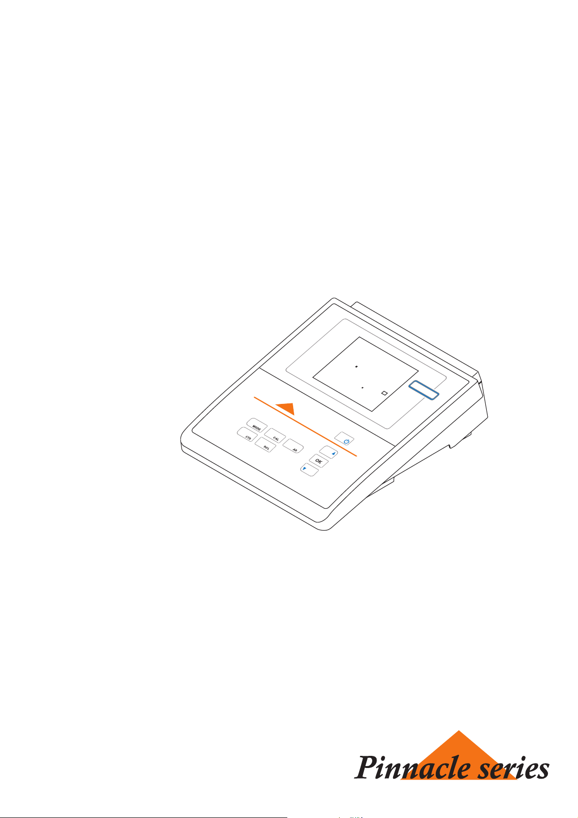
M545P
Operating manual
Pinnacle series
6
2
9
4
8
9
p
H
2
°
C
TP
M 545P
Laboratory pH meter
ba75564e03 02/2007
Page 2

M 545P
Accuracy when
going to press
Warranty We guarantee the meter described for 3 years from the date of purchase.
The use of advanced technology and the high quality standard of our meters
are the result of a continuous development. This may result in differences
between this operating manual and your meter. Also, we cannot guarantee
that there are absolutely no errors in this manual. Therefore, we are sure you
will understand that we cannot accept any legal claims resulting from the
data, figures or descriptions.
The meter warranty covers manufacturing faults that are discovered within
the warranty period.
The warranty does not cover components that are replaced during
maintenance work, e. g. batteries.
The warranty claim extends to restoring the meter to readiness for use but
not, however, to any further claim for damages. Improper handling or
unauthorized opening of the meter invalidates any warranty claim.
To ascertain the warranty liability, return the meter and proof of purchase
together with the date of purchase freight paid or prepaid.
ba75564e03 02/2007
Page 3

M545P
ba75564e03 02/2007
3
Page 4

M545P
4
ba75564e03 02/2007
Page 5

M 545P Contents
M 545P - Contents
1 Overview . . . . . . . . . . . . . . . . . . . . . . . . . . . . . . . . . . . . . 7
1.1 Keypad . . . . . . . . . . . . . . . . . . . . . . . . . . . . . . . . . . . . . . . 8
1.2 Display . . . . . . . . . . . . . . . . . . . . . . . . . . . . . . . . . . . . . . . 9
1.3 Socket field . . . . . . . . . . . . . . . . . . . . . . . . . . . . . . . . . . . 10
2 Safety . . . . . . . . . . . . . . . . . . . . . . . . . . . . . . . . . . . . . . . 11
2.1 Authorized use . . . . . . . . . . . . . . . . . . . . . . . . . . . . . . . . 12
2.2 General safety instructions . . . . . . . . . . . . . . . . . . . . . . . 12
3 Commissioning. . . . . . . . . . . . . . . . . . . . . . . . . . . . . . . 15
3.1 Scope of delivery. . . . . . . . . . . . . . . . . . . . . . . . . . . . . . . 15
3.2 Initial commissioning . . . . . . . . . . . . . . . . . . . . . . . . . . . . 15
4 Operation. . . . . . . . . . . . . . . . . . . . . . . . . . . . . . . . . . . . 17
4.1 Switching on the meter . . . . . . . . . . . . . . . . . . . . . . . . . . 17
4.2 General operating principles . . . . . . . . . . . . . . . . . . . . . . 18
4.2.1 Operating modes . . . . . . . . . . . . . . . . . . . . . . . . 18
4.2.2 Operation . . . . . . . . . . . . . . . . . . . . . . . . . . . . . . 18
4.3 Measuring . . . . . . . . . . . . . . . . . . . . . . . . . . . . . . . . . . . . 19
4.3.1 Measuring the pH value . . . . . . . . . . . . . . . . . . . 20
4.3.2 Measuring the ORP . . . . . . . . . . . . . . . . . . . . . . 21
4.4 Calibration . . . . . . . . . . . . . . . . . . . . . . . . . . . . . . . . . . . . 22
4.4.1 Calibration interval (Int.C) . . . . . . . . . . . . . . . . . 27
4.4.2 Automatic calibration Automatic Calibration
(AutoCal) . . . . . . . . . . . . . . . . . . . . . . . . . . . . . . 28
4.4.3 Conventional calibration (ConCal) . . . . . . . . . . . 31
4.5 Storage in memory . . . . . . . . . . . . . . . . . . . . . . . . . . . . . 33
4.5.1 Manual storage . . . . . . . . . . . . . . . . . . . . . . . . . 33
4.5.2 Automatic storage at intervals . . . . . . . . . . . . . . 35
4.5.3 Downloading the data memory . . . . . . . . . . . . . 37
4.5.4 Erasing the data memory . . . . . . . . . . . . . . . . . . 38
4.5.5 Downloading calibration data . . . . . . . . . . . . . . . 38
4.6 Transmitting data . . . . . . . . . . . . . . . . . . . . . . . . . . . . . . 41
4.6.1 Options for data transmission . . . . . . . . . . . . . . 41
4.6.2 Automatically downloading measurement datasets
at intervals . . . . . . . . . . . . . . . . . . . . . . . . . . . . . 42
4.6.3 Downloading stored measurement datasets . . . 42
4.6.4 Downloading calibration data . . . . . . . . . . . . . . . 42
4.6.5 RS232 interface . . . . . . . . . . . . . . . . . . . . . . . . . 42
4.7 Settings . . . . . . . . . . . . . . . . . . . . . . . . . . . . . . . . . . . . . . 44
ba75564e03 02/2007
5
Page 6

Contents M 545P
4.7.1 System settings . . . . . . . . . . . . . . . . . . . . . . . . . 45
4.7.2 Measurement settings . . . . . . . . . . . . . . . . . . . . 47
4.7.3 Interval for automatic storing (AutoStore) . . . 51
4.7.4 Interval for automatic data transmission . . . . . . . 52
4.8 Reset . . . . . . . . . . . . . . . . . . . . . . . . . . . . . . . . . . . . . . . . 53
4.8.1 Resetting calibration values . . . . . . . . . . . . . . . . 53
4.8.2 Resetting meter settings. . . . . . . . . . . . . . . . . . . 54
5 Maintenance, cleaning, disposal . . . . . . . . . . . . . . . . . 55
5.1 Maintenance . . . . . . . . . . . . . . . . . . . . . . . . . . . . . . . . . . 55
5.1.1 Replacing the batteries. . . . . . . . . . . . . . . . . . . . 55
5.2 Cleaning. . . . . . . . . . . . . . . . . . . . . . . . . . . . . . . . . . . . . . 56
5.3 Packing . . . . . . . . . . . . . . . . . . . . . . . . . . . . . . . . . . . . . . 56
6 What to do if... . . . . . . . . . . . . . . . . . . . . . . . . . . . . . . . . 57
7 Technical data . . . . . . . . . . . . . . . . . . . . . . . . . . . . . . . . 61
7.1 General data . . . . . . . . . . . . . . . . . . . . . . . . . . . . . . . . . . 61
7.2 Measuring ranges, resolution, accuracy . . . . . . . . . . . . . 63
8 Lists . . . . . . . . . . . . . . . . . . . . . . . . . . . . . . . . . . . . . . . . 65
6
ba75564e03 02/2007
Page 7
M 545P Overview
1Overview
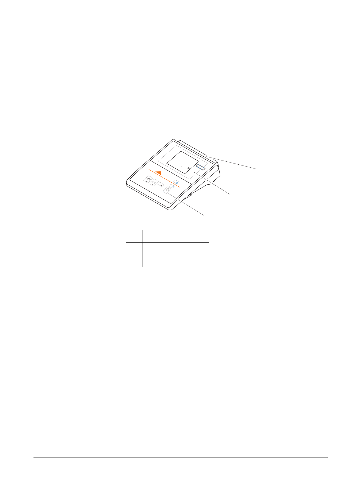
The compact M 545P precision pH meter enables you to perform pH
measurements rapidly and reliably. The M 545P provides the
maximum degree of operating comfort, reliability and measuring
certainty for all applications.
The proven calibration procedures and special AutoRead function (AR)
support your work with the pH meter.
pH
6
9
9
2
2
Pinnacle series
4
M
8
5
4
°
5
C
TP
P
3
2
1 Keypad
2 Display
3 Socket field
1
ba75564e03 02/2007
7
Page 8
Overview M 545P
STO
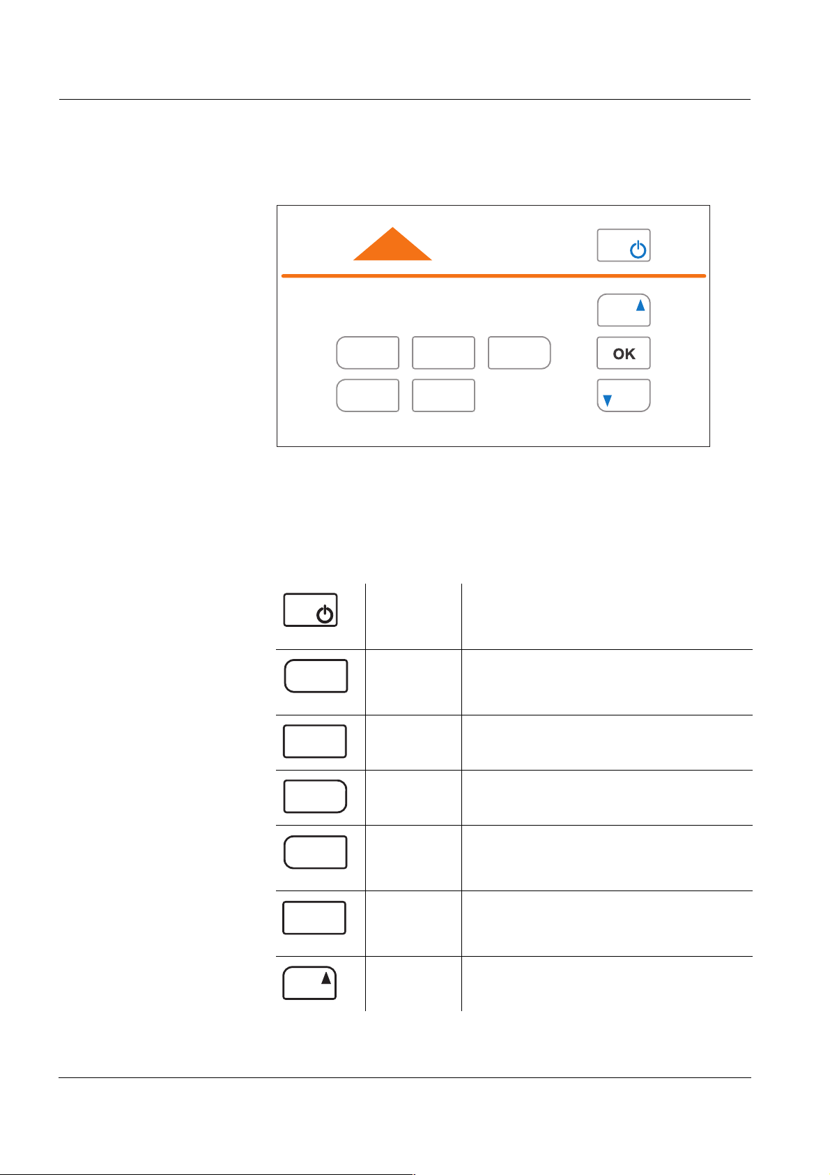
1.1 Keypad
Pinnacle series
_
_>:
CAL
RCL
Switch the measuring instrument on/off
Call up calibration data
Select measured parameter
Open setting menu for calibration and
measurement
Call up calibration procedure
Call up initialization
MODE AR
STO
In this operating manual, keys are indicated by brackets <..> .
The key symbol (e.g. <OK>) generally indicates a short keystroke
(under 2 sec) in this operating manual. A long keystroke (approx.
2 sec) is indicated by the underscore behind the key symbol (e.g.
<OK
_>).
<On/Off>:
<On/
Off
_>:
<MODE>:
MODE
CAL
<MODE
>:
<CAL>:
<CAL
<AR>:
_>:
AR
STO
RCL
8
<AR
<STO>:
_>:
<STO
<RCL>:
<RCL
_>:
<▲>: Increment values, scroll
Activate / deactivate AutoRead
Set the interval for data transmission
Store measured value
Set the interval for automatic storing
processes
Display / transmit measured values and
calibration records
Erase stored measured values
ba75564e03 02/2007
Page 9
M 545P Overview
<▼>: Decrement values, scroll
Function display
indicators
<OK>:
_>:
<OK
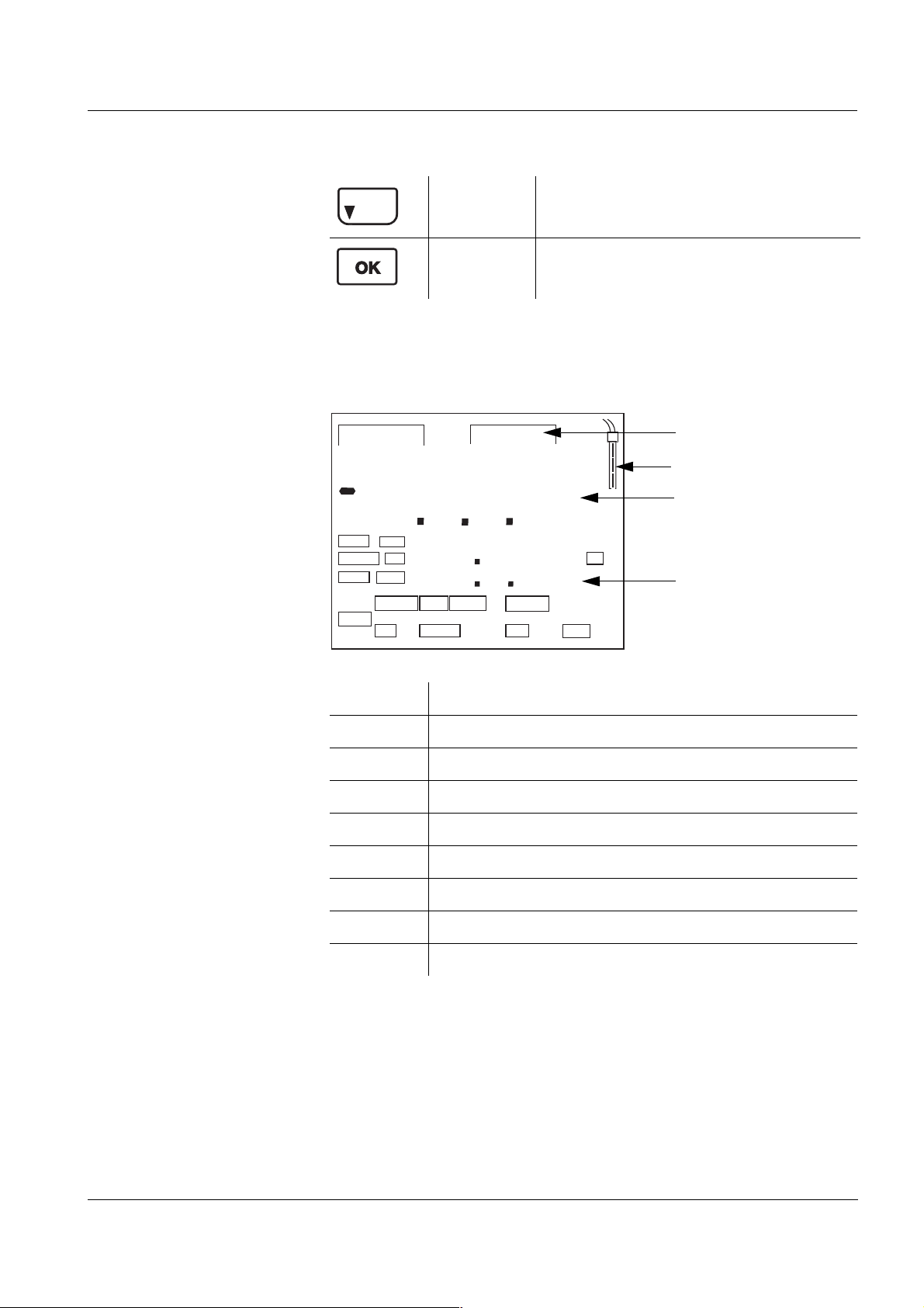
1.2 Display
SET
1
Time
Day.Month
Year
AutoCal
LoBat
DIN
SET During calibration: number of the buffer set
BUFFER During calibration: number of the buffer
U pH
8
8
Baud
No.
Ident
88
Auto
BUFFER
8
8
Store
Confirm entries
Open setting menu for system settings
Status display
Sensor symbol
8
8
CalError
ARConCal
%
mV/pH
°F
°
C
RCL
TP
Measured value
display
Function and
temperature display
indicators
AutoCal Calibration with automatic buffer recognition
AutoStore Automatic storing is switched on
CalError An error occurred during calibration
LoBat With battery operation: batteries almost empty
AR AutoRead is active
RCL Memory display / memory download
TP Temperature measurement active
ba75564e03 02/2007
9
Page 10
Overview M 545P
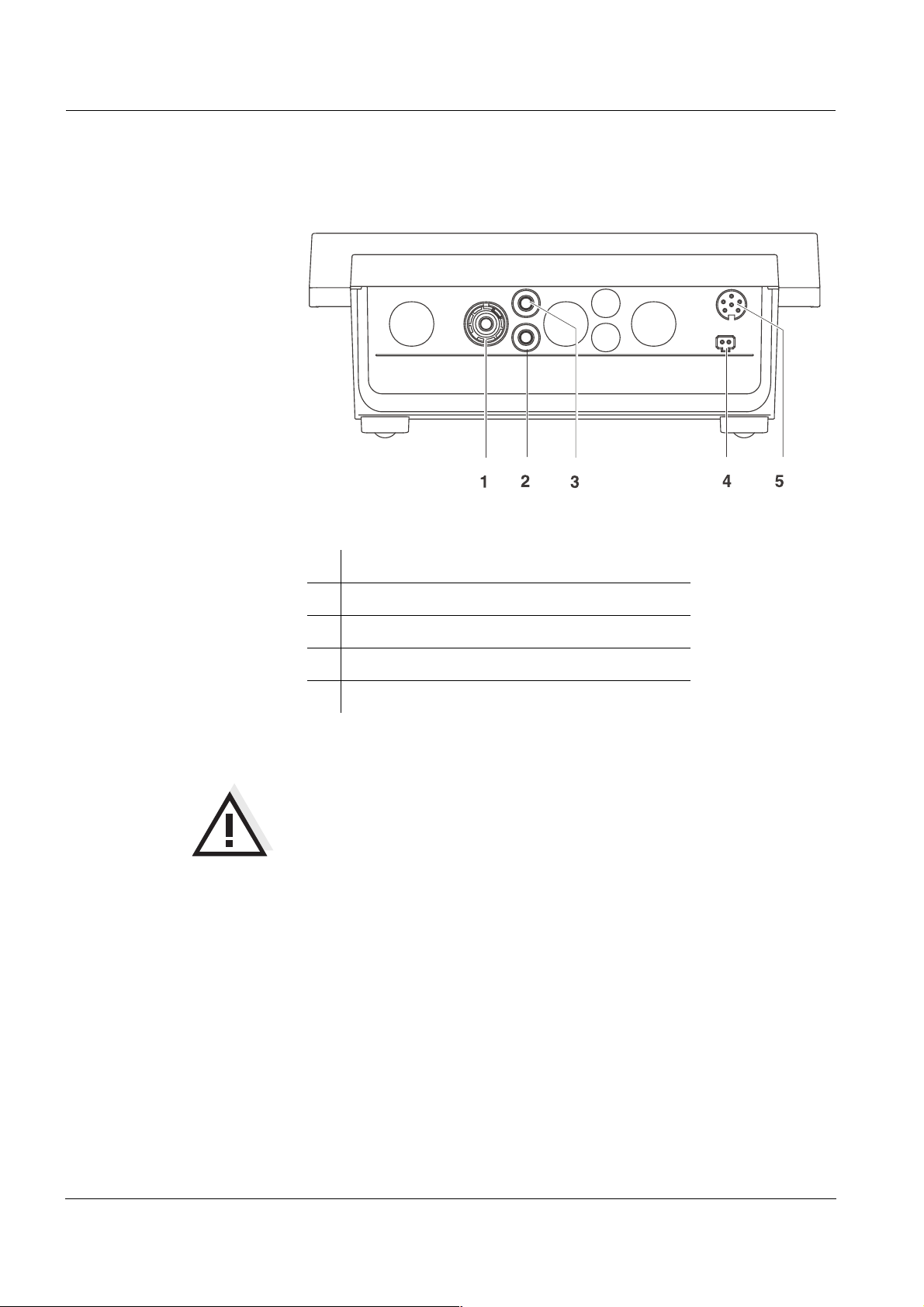
1.3 Socket field
Connectors:
1 pH electrode
2 Reference electrode
3 Temperature sensor
4 Power pack
5 RS 232 interface
Caution
Only connect sensors to the meter that cannot return any voltages
or currents that are not allowed (> SELV and > current circuit with
current limiting).
Almost all customary sensors fulfill these conditions.
10
ba75564e03 02/2007
Page 11
M 545P Safety
2 Safety
This operating manual contains basic instructions that you must follow
during the commissioning, operation and maintenance of the meter.
Consequently, all responsible personnel must read this operating
manual before working with the meter.
The operating manual must always be available within the
vicinity of the meter.
Target group The meter was developed for work in the laboratory.
Thus, we assume that, as a result of their professional training and
experience, the operators will know the necessary safety precautions
to take when handling chemicals.
Safety instructions Safety instructions in this operating manual are indicated by the
warning symbol (triangle) in the left column. The signal word (e.g.
"Caution") indicates the level of danger:
Further notes
Warning
indicates instructions that must be followed precisely in order to
avoid possibly great dangers to personnel.
Caution
indicates instructions that must be followed precisely in order to
avoid the possibility of slight injuries or damage to the meter or
the environment.
Note
indicates notes that draw your attention to special features.
Note
indicates cross-references to other documents, e.g. operating
manuals.
ba75564e03 02/2007
11
Page 12

Safety M 545P
2.1 Authorized use
This meter is authorized exclusively for pH and ORP measurements in
the laboratory.
The technical specifications as given in chapter 7 T
ECHNICAL DATA must
be observed. Only the operation and running of the meter according to
the instructions given in this operating manual is authorized.
Any other use is considered unauthorized.
2.2 General safety instructions
This meter is constructed and tested in compliance with the IEC 1010
safety regulations for electronic measuring instruments.
It left the factory in a safe and secure technical condition.
Function and
operational safety
The smooth functioning and operational safety of the meter can only be
guaranteed if the generally applicable safety measures and the specific
safety instructions in this operating manual are followed during
operation.
The smooth functioning and operational safety of the meter can only be
guaranteed under the environmental conditions that are specified in
chapter 7 T
ECHNICAL DATA.
If the meter was transported from a cold environment to a warm
environment, the formation of condensate can lead to the faulty
functioning of the meter. In this event, wait until the temperature of the
meter reaches room temperature before putting the meter back into
operation.
Caution
The meter is only allowed to be opened by authorized personnel.
12
ba75564e03 02/2007
Page 13

M 545P Safety
Safe operation If safe operation is no longer possible, the meter must be taken out of
service and secured against inadvertent operation!
Safe operation is no longer possible if the meter:
z has been damaged in transport
z has been stored under adverse conditions for a lengthy period of
time
z is visibly damaged
z no longer operates as described in this manual.
If you are in any doubt, please contact the supplier of the meter.
Obligations of the
purchaser
The purchaser of this meter must ensure that the following laws and
guidelines are observed when using dangerous substances:
z EEC directives for protective labor legislation
z National protective labor legislation
z Safety regulations
z Safety datasheets of the chemical manufacturers.
ba75564e03 02/2007
13
Page 14

Safety M 545P
14
ba75564e03 02/2007
Page 15
M 545P Commissioning
3 Commissioning
3.1 Scope of delivery
z M 545P laboratory meter
z Power pack
z 4 batteries 1.5 V Mignon type AA
z Stand with stand base
z Operating manual
3.2 Initial commissioning
Perform the following activities:
z Switch on the meter
Switching on the meter
Setting the date and
time
Connecting the power
pack
z Set the date and time
z Connect the power pack (for line power operation only).
1 Switch on the meter with <On/Off>.
A display test is briefly displayed.
2 See section 4.7.1
Caution
The line voltage at the operating site must lie within the input
voltage range of the original power pack (see chapter 7 T
DATA).
ECHNICAL
Caution
Use original power packs only (see chapter 7 TECHNICAL DATA).
ba75564e03 02/2007
3 Insert the plug into the socket of the pH meter.
4 Connect the original power pack to an easily accessible power
outlet.
Note
You can carry out measurements without the power pack.
15
Page 16

Commissioning M 545P
16
ba75564e03 02/2007
Page 17

M 545P Operation
4 Operation
4.1 Switching on the meter
1 Place the meter on a flat surface and protect it from intense
light and heat.
2 Press the <On/Off>
A display test is briefly displayed.
Subsequently, the meter switches to the measuring mode
(measured value display).
Note
The meter has an energy saving feature to avoid unnecessary battery
depletion during battery operation.
The energy saving feature switches off the meter if no key was pressed
during the specified interval (setting the switch-off interval see section
4.7.1).
The energy saving feature is not active:
z if the power is supplied by the power pack
z if the AutoStore function is active (see section 4.5.2)
z if a PC is connected (with communication cable to RS232 interface)
z if the printer cable is connected (for external printers).
key.
ba75564e03 02/2007
17
Page 18

Operation M 545P
4.2 General operating principles
This section contains basic information on the operation of the M 545P.
4.2.1 Operating modes
The meter has the following operating modes:
z Measurement
The display indicates the measurement data in the measured value
display
z Calibration
The display guides you thru a calibration procedure with calibration
information
z Storage in memory
The meter stores measuring data automatically or manually
z Data transmission
The meter transmits measuring data and calibration records to a
serial interface automatically or manually.
z Configuration
The system menu or a sensor menu with submenus, settings and
functions is displayed
4.2.2 Operation
Keys The meter is operated via keys. The keys can have different functions
with long or short keystrokes.
Functions Generally, with a short keystroke a function is carried out. A long
keystroke opens a setting menu.
In a setting menu, settings are selected with the <▲><▼> keys.
A setting is confirmed with <OK>. With confirming, the setting is
finished and the next setting is displayed.
Representation In this operating manual, keys are indicated by brackets <..> .
The key symbol (e.g. <OK>) generally indicates a short keystroke
(under 2 sec) in this operating manual. A long keystroke (approx.
2 sec) is indicated by the underscore behind the key symbol (e.g.
<OK
_>).
18
ba75564e03 02/2007
Page 19
M 545P Operation
4.3 Measuring
Preparatory activities Perform the following preparatory activities when you want to measure:
1 Connect an electrode to the meter.
2 Adjust the temperature of the buffer solutions or test solutions,
or measure the current temperature, if you measure without a
temperature sensor.
3 Calibrate or check the meter with the electrode.
4 Select the measured parameter with <MODE>.
Note
Incorrect calibration of pH electrodes leads to incorrect measured
values. Calibrate regularly before measuring.
Caution
When connecting an earthed PC/printer, measurements cannot be
performed in earthed media as incorrect values would result.
The RS232 interface is not galvanically isolated.
Temperature sensor You can measure with or without a temperature sensor. If a
temperature sensor is connected, it is indicated on the display by TP.
Note
The pH meter automatically recognizes the type of the temperature
sensor used. Therefore, you can connect electrodes with an NTC30 or
Pt1000.
The temperature measurement is absolutely essential for a
reproducible pH measurement. If the measurement is made without a
temperature sensor, proceed as follows:
1 Measure the current temperature using a thermometer.
2 Set the temperature value with <▲><▼>.
Note
When calibrating without temperature sensor, also set the current
temperature of each buffer solution manually with the <▲><▼>
keys.
ba75564e03 02/2007
19
Page 20
Operation M 545P
4.3.1 Measuring the pH value
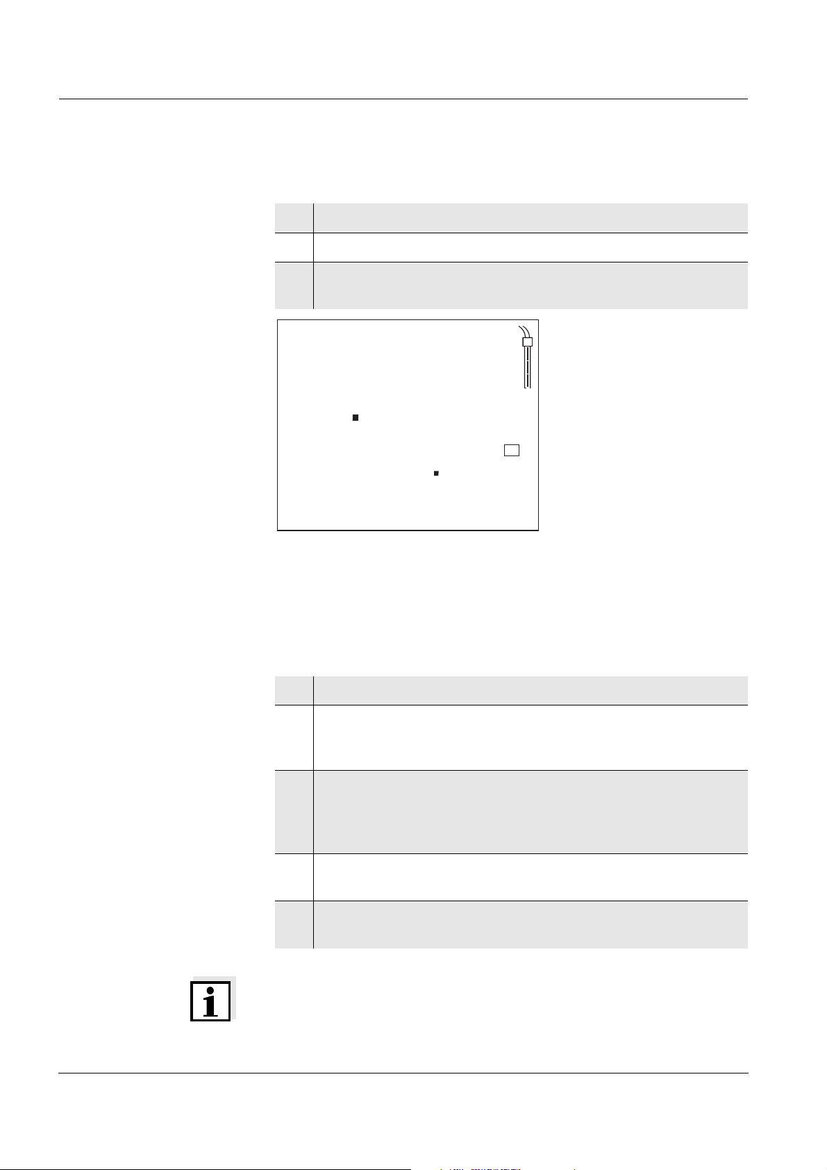
1 Perform the preparatory activities according to section 4.3.
2 Immerse the pH electrode in the test sample.
3 Using <MODE>, scroll as necessary until the measured
parameter pH is displayed.
pH
AutoRead AR
(drift control)
9
4
2
8
TP
°
C
9
6
2
The AutoRead function (drift control) checks the stability of the
measurement signal. The stability has a considerable effect on the
reproducibility of the measured value.
For identical measurement conditions, the following criteria apply:
Drift within 15 sec < 0.02 pH units.
1 If necessary, call up the measured variable pH with <MODE>.
2With <AR>, activate the AutoRead function.
The AR function display indicator appears.
The current measured value is frozen (hold function).
3 Start measurement with AutoRead with <OK>.
The AR display indicator flashes until a stable value is
measured.
This measured value is downloaded to the interface.
20
4 If necessary, start the next measurement with AutoRead with
<OK>.
5 To terminate the AutoRead function: press the <MODE> or
<AR>
key.
Note
The current measurement with AutoRead can be terminated at any
time (accepting the current value) by pressing <OK>.
ba75564e03 02/2007
Page 21
M 545P Operation
4.3.2 Measuring the ORP
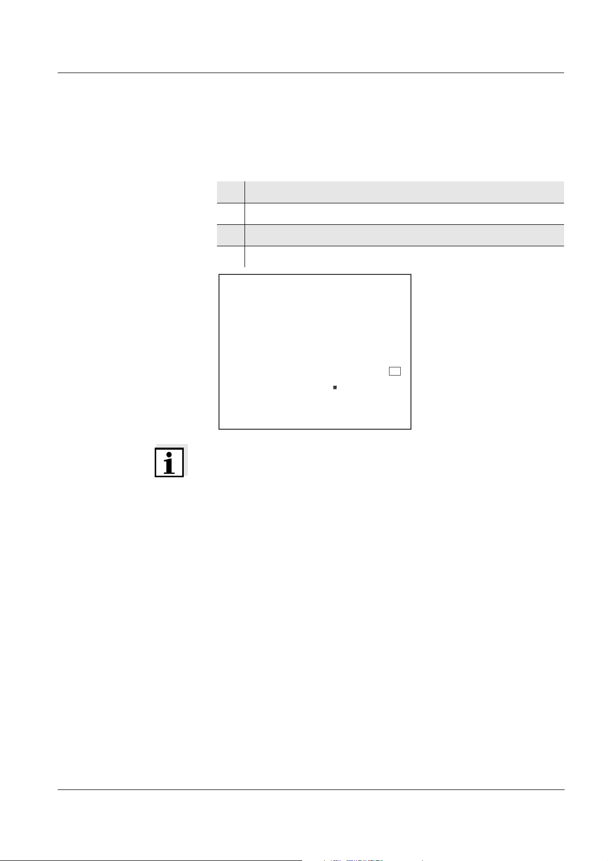
The meter can, in conjunction with an ORP electrode, measure the
ORP (mV) of a solution.
1 Perform the preparatory activities according to section 4.3.
2 Immerse the ORP electrode in the test sample.
3 If necessary, call up the measured parameter U with <MODE>.
4 Wait for a stable measured value.
U
°
mV
TP
C
4
8
2
Note
ORP electrodes are not calibrated. However, you can check ORP
electrodes using a test solution.
6
1
3
ba75564e03 02/2007
21
Page 22

Operation M 545P
4.4 Calibration
Why calibrate? pH electrodes age. This changes the zero point (asymmetry) and slope
of the pH electrode. As a result, an inexact measured value is
displayed. Calibration determines the current values of the zero point
and slope of the electrode and stores them in the meter. Thus, you
should calibrate at regular intervals.
When do you have to
calibrate?
AutoCal is adapted to the permanently programmed buffer solutions as a fully
Buffer sets for
calibration
z After connecting another electrode
z When the sensor symbol flashes on the display:
– after the calibration interval has expired
– after a voltage interruption (empty batteries)
automatic single-point, two-point or three-point calibration. The buffer
solutions are automatically recognized by the meter.
You can use the buffer sets quoted in the table for an automatic
calibration. The pH values are valid for the specified temperature
values. The temperature dependence of the pH values is taken into
consideration during the calibration.
No. Buffer set * pH values at
1 Buffers according to DIN 19266 and
NIST Retraceable Buffers
1.679
4.006
25 °C
6.865
9.180
12.454
22
2 Technical buffers 2.000
4.010
7.000
10.011
3 Merck1* 4.000
7.000
9.000
4 Merck2 * 1.000
6.000
8.000
13.000
5 Merck3 * 4.660
6.880
9.220
ba75564e03 02/2007
25 °C
20°C
20°C
20°C
Page 23

M 545P Operation
No. Buffer set * pH values at
6 DIN 19267 1 1.090
4.650
6.790
9.230
7 Mettler Toledo USA * 1.679
4.003
7.002
10.013
8 Mettler Toledo TEC * 1.995
4.005
7.002
9.208
9 Fisher * 2.007
4.002
7.004
10.002
10 Fluka BS * 4.006
6.984
8.957
11 Radiometer * 1.678
4.005
7.000
9.180
25 °C
25 °C
25 °C
25 °C
25 °C
25 °C
12 Baker * 4.006
25 °C
6.991
10.008
13 Metrohm * 3.996
25 °C
7.003
8.999
14 Beckman * 4.005
25 °C
7.005
10.013
15 Hamilton Duracal * 4.005
25 °C
7.002
10.013
16 Precisa * 3.996
25 °C
7.003
8.999
* Brand names or trade names are trademarks of their respective owners
protected by law (see page 69).
ba75564e03 02/2007
23
Page 24

Operation M 545P
Note
The buffer set is selected in the menu for measurement settings (see
section 4.7.2).
A list of the stored buffer sets can be downloaded to the interface (Set
1 ... 16) with <CAL
measurement settings.
Calibration points Calibration can be performed using one, two or three buffer solutions in
any order (single-point, two-point or three-point calibration).The meter
determines the following values and calculates the calibration line as
follows:
_> while selecting the buffer set in the menu for
Determined
values
1-point ASY z Zero point = ASY
2-point ASY
SLO
3-point ASY
SLO
Note
You can display the slope in the units, mV/pH or %.
You can display the zero point in the units, mV or pH.
ConCal This function is a conventional two-point calibration using two buffer
solutions (pH 7.0 ± 0.5 and any other buffer solution) or a single-point
calibration using any buffer solution and is used as a high-speed
method.
Displayed calibration data
z Slope = Nernst slope
(-59.16 mV/pH at 25 °C)
z Zero point = ASY
z Slope = SLO
z Zero point = ASY
z Slope = SLO
The calibration line is calculated
by linear regression.
24
AutoRead The calibration procedure automatically activates the AutoRead
function.
The current measurement with AutoRead can be terminated at any
time (accepting the current value) by pressing <OK>.
Calibration record When finishing a calibration, the new calibration values are first
displayed as an informative message and stored.
ba75564e03 02/2007
Page 25

M 545P Operation
Displaying the
calibration data
You can display the data of the last calibration (see ). Subsequently,
you can transmit the displayed calibration data to the interface, e. g. to
a printer or PC, with the <CAL
_> key.
Note
The calibration record is automatically transmitted to the interface after
calibrating.
Sample record:
16.09.2005 08:53:54
M 545P 02320025
Calibration pH
Cal time: 16.09.2005 08:22:14
Cal interval: 14d
Buffer 1 2.000
Buffer 2 4.010
Buffer 3 7.000
Buffer 4 10.011
b1 -177.0 mV 25.0 °C
b2 177.0 mV 25.0 °C
b3 0.0 mV 25.0 °C
Slope : -58.99 mV/pH
Asymmetry : 0.4 mV
Sensor : +++
AutoCal
Calibration evaluation After calibrating, the meter automatically evaluates the calibration. The
zero point and slope are evaluated separately. The worse evaluation of
both is taken into account. The evaluation appears on the display as
the sensor symbol and in the calibration record.
Sensor symbol Calibration
record
Zero point
[mV]
Slope
[mV/pH]
+++ -15 ... +15 -60.5 ... -58
++ -20 ... +20 -58 ... -57
+ - 25 ... + 25 -61 ... -60.5
or
-57 ... -56
ba75564e03 02/2007
25
Page 26

Operation M 545P
Preparatory activities
Sensor symbol Calibration
record
- -30 ... +30 -62 ... -61
Clean the electrode
according to the
sensor operating
manual
CalError CalError
Eliminate the error according to
chapter 6 W
HAT TO DO IF...
1 Switch on the meter with <On/Off>.
2 Connect a pH electrode to the meter.
Zero point
[mV]
< -30 or
> 30
Slope
[mV/pH]
or
-56 ... -50
... -62 or
... -50
3 Keep the buffer solutions ready.
4 Adjust the temperature of the solutions and measure the
current temperature if the measurement is made without
temperature sensor.
5 Set the buffer set to be used for calibration as necessary.
26
ba75564e03 02/2007
Page 27
M 545P Operation
4.4.1 Calibration interval (Int.C)
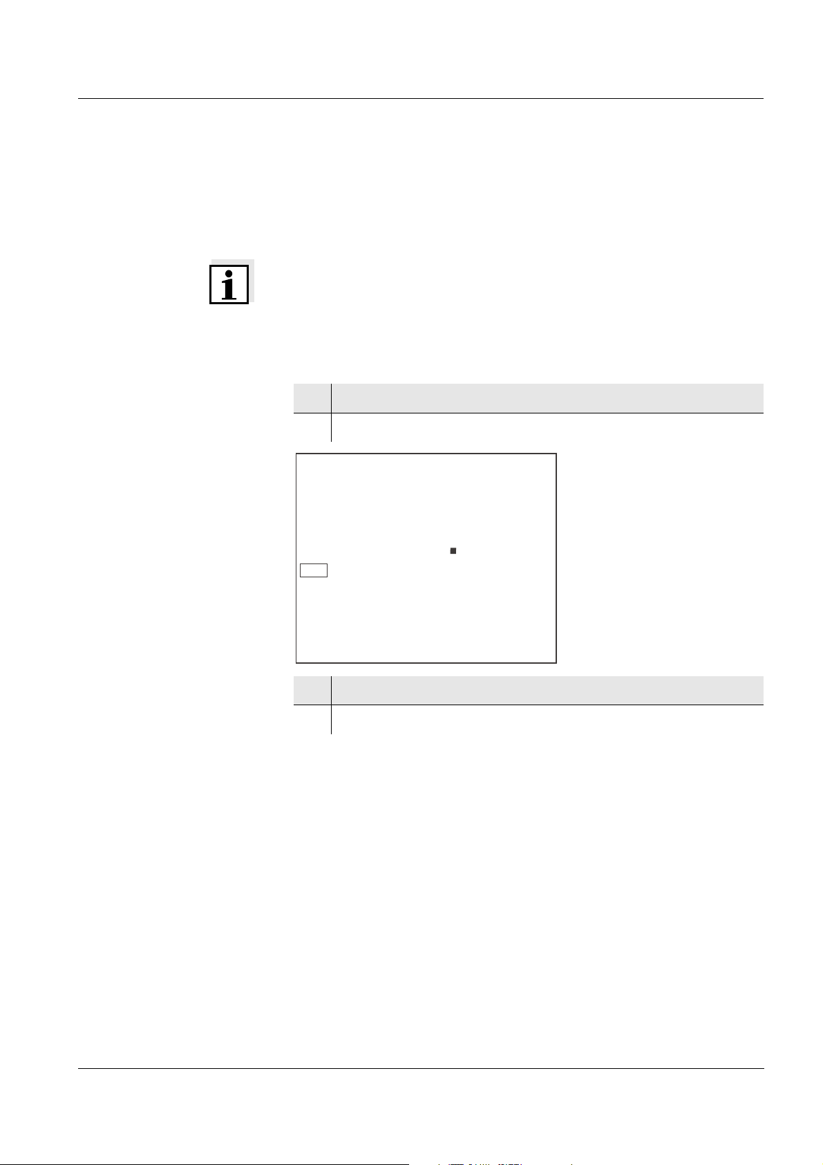
The calibration interval reminds you to calibrate regularly. When the
adjusted calibration interval (Int.C) has expired, the sensor symbol
flashes. It is still possible to measure.
Note
To ensure the high measuring accuracy of the measuring system,
calibrate after the calibration interval has expired.
Setting the calibration
interval
The calibration interval (Int.C) is set to 7 days (d7) in the factory.
You can change the interval (1 ... 999 days):
1 Open the menu for measurement settings with <MODE_>.
2 Confirm all settings with <OK> until Int.C is displayed.
pH
T
C
8
N
1
Time
D
3 Set the calibration interval with <▲><▼>.
4 Confirm the setting with <OK>.
ba75564e03 02/2007
27
Page 28
Operation M 545P
4.4.2 Automatic calibration Automatic Calibration (AutoCal)
For this procedure, use two or three buffer solutions of the selected
buffer set in any order.
Note
The steps 2, 6 and 10 are not necessary if you use a temperature
sensor.
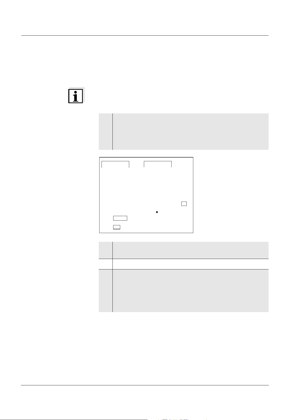
1 Start the calibration with <CAL>.
The number of the specified buffer set is displayed (SET 1 ...
16).
The first buffer (BUFFER 1) of the buffer set (SET_x) is
requested.
2
Buffer
5
1
8
TP
°
C
SET
pH
1
AutoCal
DIN
2 If necessary, set the temperature of the buffer solution with
<▲><▼>.
3 Immerse the pH electrode in the first buffer solution.
4 Start the measurement with <OK>.
The AR display indicator flashes.
Depending on the setting, the display shows the nominal pH
value for the recognized buffer or the electrode voltage (mV).
As soon as a stable value is recognized, the next buffer
(BUFFER 2) is requested.
28
ba75564e03 02/2007
Page 29
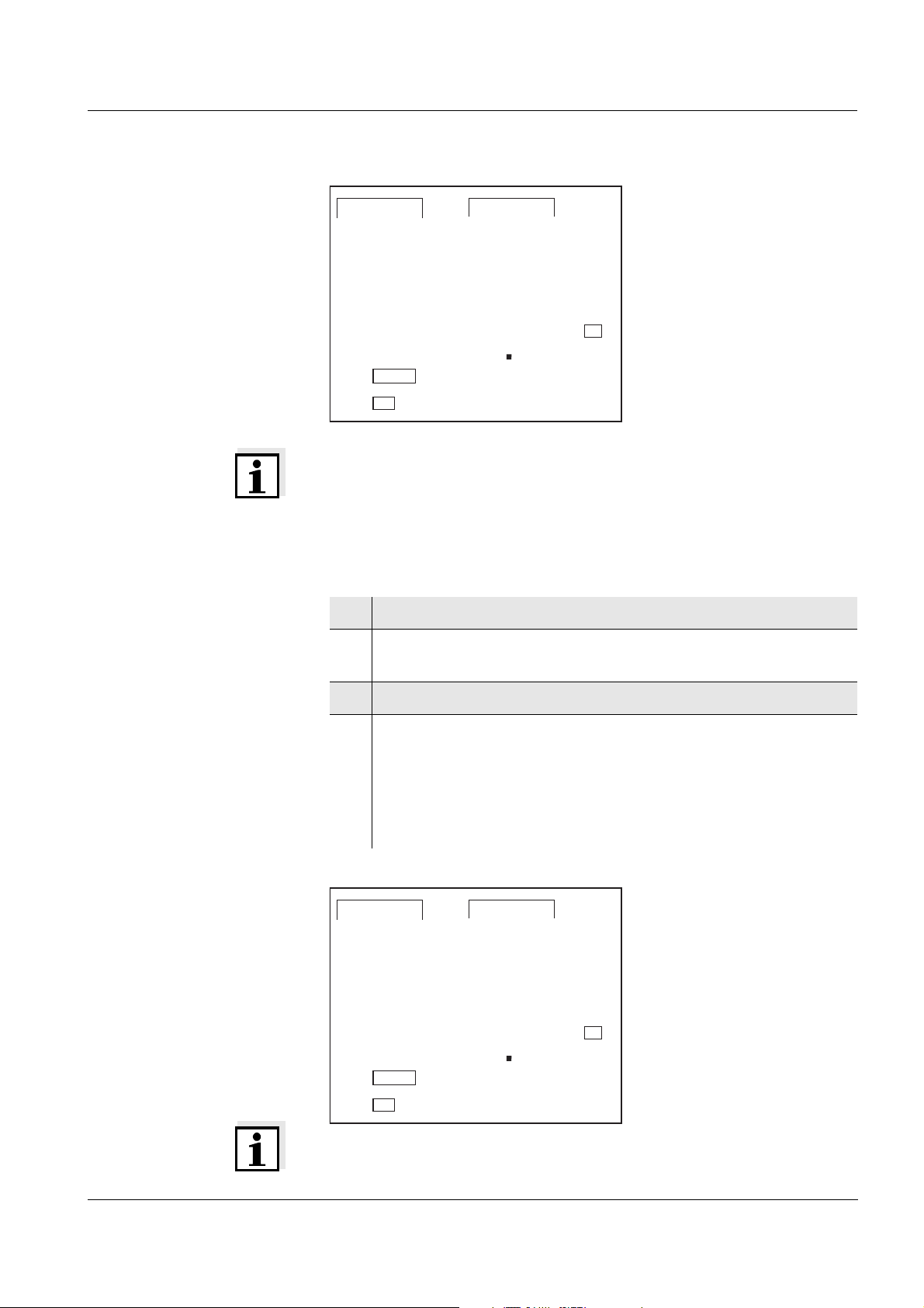
M 545P Operation
Continuing with two-
point calibration
2
Buffer
5
2
8
TP
°
C
SET
pH
1
AutoCal
DIN
Note
Here you can cancel the calibration procedure with <MODE>. This
corresponds to a single-point calibration. The value of the zero point
(ASY) is displayed for 10 seconds, then the value of the slope (SLO) is
displayed for 10 seconds. After this the meter switches to the
measuring mode.
5 Thoroughly rinse the electrode with distilled water.
6 If necessary, set the temperature of the second buffer solution
with <▲><▼>.
7 Immerse the electrode in the second buffer solution.
8 Start the measurement with <OK>.
The AR display indicator flashes.
Depending on the setting, the display shows the nominal pH
value for the recognized buffer or the electrode voltage (mV).
As soon as a stable value is recognized, the next buffer
(BUFFER 3) is requested.
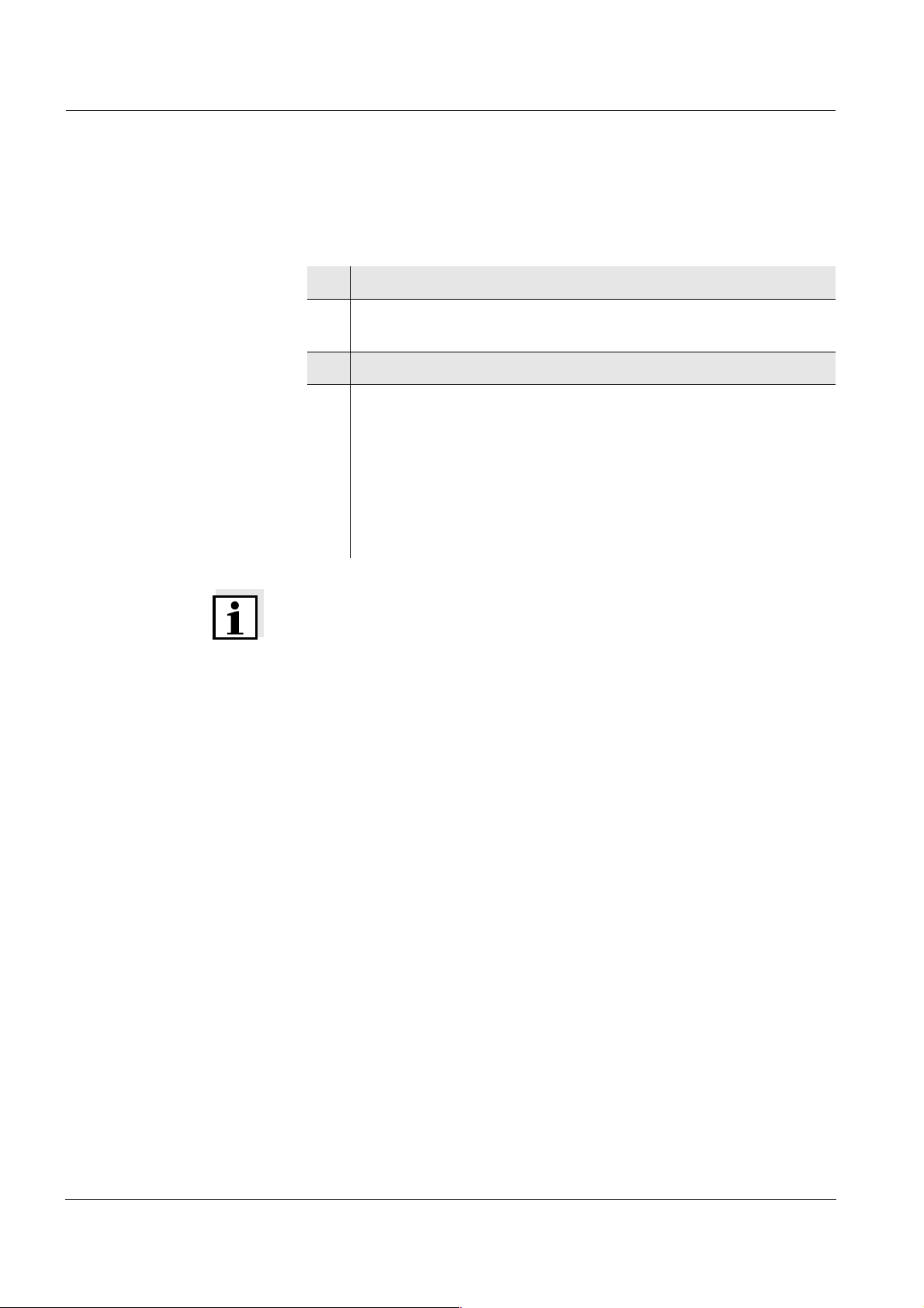
2
Buffer
5
3
8
TP
°
C
SET
pH
1
AutoCal
DIN
Note
Here you can cancel the calibration procedure with <MODE>. This
corresponds to a two-point calibration. The value of the zero point
ba75564e03 02/2007
29
Page 30
Operation M 545P
(ASY) is displayed for 10 seconds, then the value of the slope (SLO) is
displayed for 10 seconds. After this the meter switches to the
measuring mode.
Continuing with three-
point calibration
9 Thoroughly rinse the electrode with distilled water.
10 If necessary, set the temperature of the third buffer solution
with <▲><▼>.
11 Immerse the pH electrode in the third buffer solution.
12 Press the <OK>
The AR display indicator flashes.
Depending on the setting, the display shows the nominal pH
value for the recognized buffer or the electrode voltage (mV).
As soon as a stable value is recognized, the value of the zero
point (ASY) is displayed for 10 seconds, then the value of the
slope (SLO) is displayed for 10 seconds.
After this the meter switches to the measuring mode.
Note
While the zero point (ASY) is being displayed, you can change the unit
of the zero point with
While the slope (SLO) is being displayed, you can change the unit of
the slope with
The % display refers to the Nernst slope of 59.2 mV/pH at 25° C
(100 x determined slope/Nernst slope).
<▲><▼>.
key.
<▲><▼>.
The unit of zero point and slope can also be changed permanently in
the measurement settings (see section 4.7.2).
30
ba75564e03 02/2007
Page 31
M 545P Operation
4.4.3 Conventional calibration (ConCal)
Single-point calibration Use any buffer solution for this rapid method.
The calibration will be the more exact the nearer the pH value of the
buffer solution is to that of the test sample.
Two-point calibration Use two buffer solutions for this procedure:
z pH 7.0 ± 0.5
z any other buffer solution
Note
The steps 2 and 9 are not necessary if you use a pH electrode with a
temperature sensor.
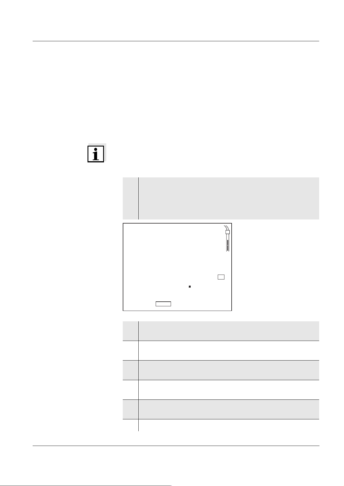
1 Press the <CAL> key repeatedly until the ASY display indicator
and the ConCal function indicator appear. The sensor symbol
displays the evaluation of the last calibration (or no sensor
symbol in the delivery state or after the measurement
parameters have been reset).
S
4
Y
8
TP
°
C
A
2
ConCal
2 If necessary, set the temperature of the first buffer solution with
<▲><▼>.
3 Immerse the pH electrode in the first buffer solution (pH 7.0 ±
0.5 for two-point calibration).
4 Press the <OK> key.
The measured pH value appears on the display.
5 Using <▲><▼>, set the measured value to the nominal pH
value of the buffer solution (at the current temperature).
6 Press the <OK> key. The value of the zero point (mV) and the
sensor symbol appear on the display.
7 Press the <OK> key. SLO appears on the display.
ba75564e03 02/2007
31
Page 32
Operation M 545P
Note
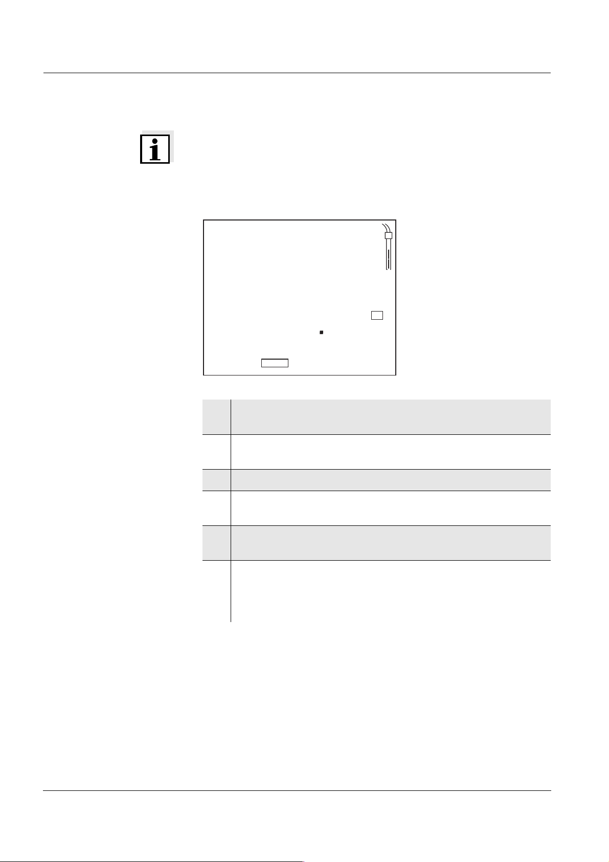
Here you can cancel the calibration procedure with <MODE>. This
corresponds to a single-point calibration. The value of the zero point
(ASY) is displayed for 10 seconds, then the value of the slope (SLO) is
displayed for 10 seconds. After this the meter switches to the
measuring mode.
L
4
O
8
TP
°
C
s
2
ConCal
8 To continue the two-point calibration, thoroughly rinse the
electrode with deionized water.
9 If necessary, set the temperature of the second buffer solution
with <▲><▼>.
10 Immerse the pH electrode in the second buffer solution.
11 Press the <OK> key. The second pH value appears on the
display.
12 Using <▲><▼>, set the measured value to the nominal pH
value of the buffer solution (at the current temperature).
13 When the measured value is stable, press the <OK> key.
The value of the zero point (ASY) is displayed for 10 seconds,
then the value of the slope (SLO) is displayed for 10 seconds.
After this the meter switches to the measuring mode.
32
ba75564e03 02/2007
Page 33
M 545P Operation
4.5 Storage in memory
The pH meter has an internal data memory. It can store up to 800
datasets.
A complete dataset consists of:
z Date/time
z Memory location
z ID number
z Measured value
z Temperature
z Temperature measuring procedure (manual or automatic)
You can transmit measured values (datasets) to the data memory in
two ways:
z Store manually (<STO>)
z Switch on AutoStore (Int.1) (<STO
4.5.1 Manual storage
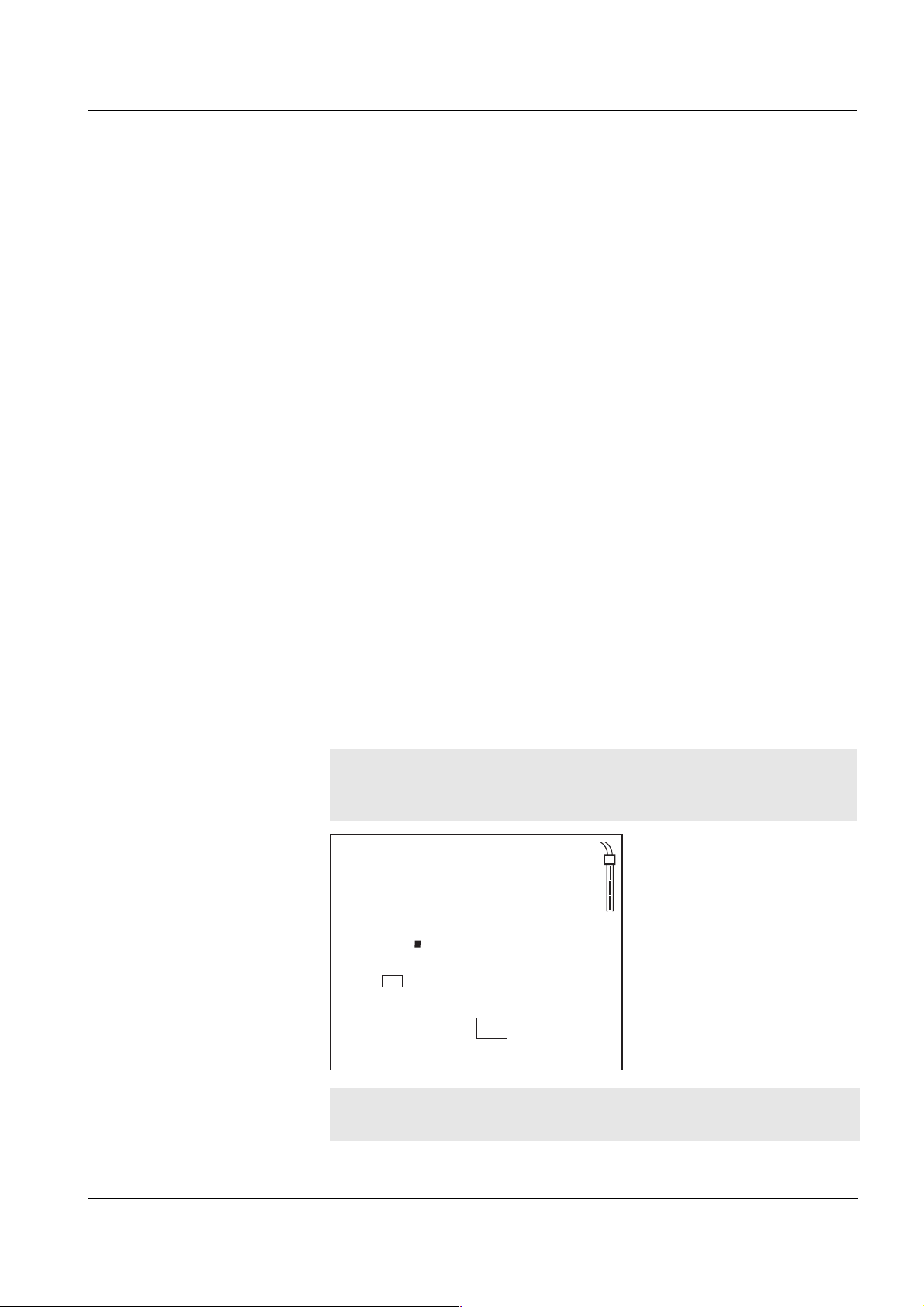
You can transmit a measured value to the data memory as follows:
1 Store the measurement dataset with <STO>.
The consecutive number of the next free memory location is
shown on the display.
pH
6
No.
9
N
9
Store
2
4
_>).
ba75564e03 02/2007
2 Confirm with <OK>.
The display switches to the entry of the ID number.
33
Page 34
Operation M 545P
pH
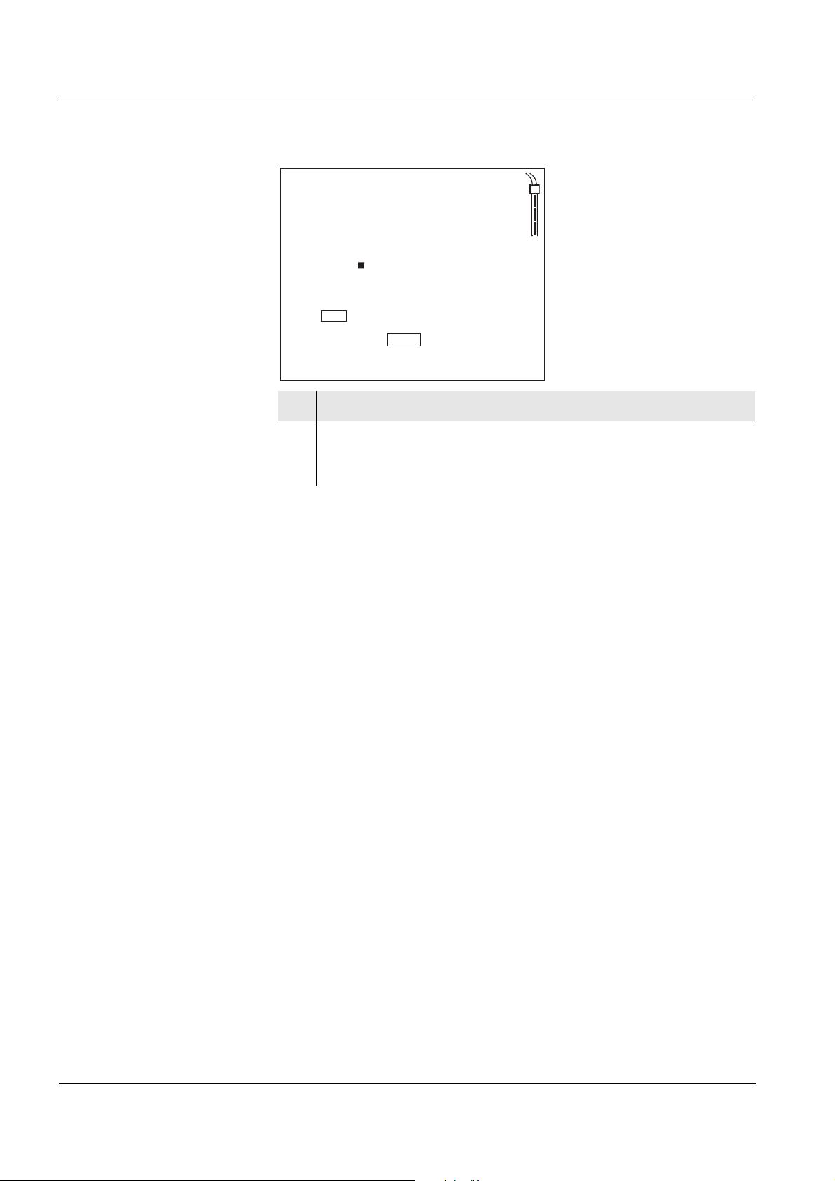
Message StoFull
StoFull This message appears when all of the 800 memory locations are
StoFullStoFull
9
6
Ident
3 Using <▲><▼>, enter the required ID number (1 ... 9999).
4 Confirm with <OK>.
The dataset is stored.
The meter switches to the measuring mode.
occupied.
When the memory is full, you can:
z press <OK> to store the current measured value.
0
00
Store
2
9
1
The oldest measured value (memory location
1) will be overwritten by this
z press <MODE> to switch to the measured value display
without storing
z download the data memory (see section 4.5.3)
z clear the memory (see section 4.5.4).
34
ba75564e03 02/2007
Page 35
M 545P Operation
4.5.2 Automatic storage at intervals
In order to store measured values automatically at certain time
intervals, set the memory interval (Int.1).
Setting the save interval The default setting for the storage interval (Int 1) is OFF.
By this, the AutoStore function is switched off.
To switch the function on, set an interval (5 s, 10 s, 30 s, 1 min, 5 min,
10 min, 15 min, 30 min, 60 min):
Note
When the AutoStore function is active, the automatic switchoff function
is off.
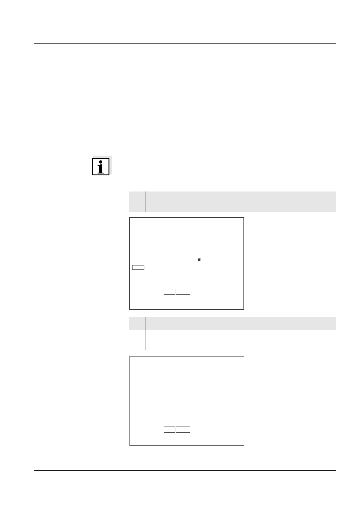
1 Using <STO_>, call up the setting menu for automatic storing
(Int.1) .
t
0
e
9
1
0
e
9
n
I
Time
1
Auto
Store
2 Set the required interval with <▲><▼>.
3 Confirm with <OK>.
FrEE, the number of free memory locations is displayed.
F
r
1
Auto
Store
ba75564e03 02/2007
35
Page 36

Operation M 545P
4 Confirm with <OK>.
Ident, the entry of the ID number is displayed.
Ident
5 Set the required ID number with <▲><▼>.
6 Confirm with <OK>.
The meter switches to the measured value display and starts
the measuring and storing procedure.
AutoStore flashes on the display.
7 As soon as all of the 800 memory locations are occupied,
AutoStore is terminated (Int.1 = OFF).
If there are not enough memory locations available for your
measurements:
– Output and backup the data memory (see section 4.5.3)
– clear the memory (see section 4.5.4).
0
00
and
1
36
Switching off the
automatic storing
function
You can terminate the automatic storing function in the following ways:
z set the storage interval (Int.1) to OFF, or
z switch the meter off and then on again.
ba75564e03 02/2007
Page 37
M 545P Operation
4.5.3 Downloading the data memory
You can download stored measurement datasets:
z to the display
z to the interface (section 4.6.1)
Download to the display
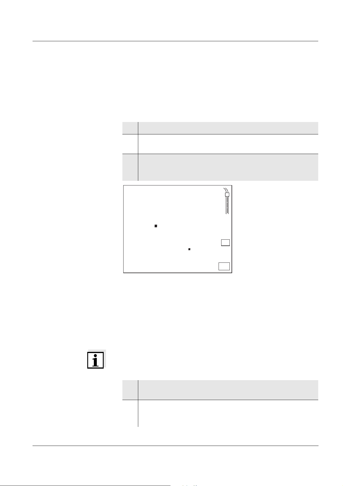
1 Open the memory menu with <RCL>.
2 If necessary, scroll with <RCL> until Sto disp (measurement
datasets) is displayed.
3 Press <OK> to display the dataset that was last stored.
The memory location of the dataset is displayed for approx.
2 s, then the respective temperature appears.
pH
6
5
6
5
TP
°
C
RCL
8
6
2
While the memory is displayed you can:
ba75564e03 02/2007
z press <OK> to display further data of the dataset (ID number,
date, time, memory location, temperature)
z press <▲> to display the next dataset
z press <▼> to display the previous dataset
Note
In order to search for certain data of the dataset, e.g. for the date,
proceed as follows:
1 Use <OK> to scroll on until the required data, e. g. the date, is
displayed.
2Use <▲> or <▼> to scroll until the required date is displayed.
After approx. 2 s the display shows the respective temperature
value.
37
Page 38

Operation M 545P
4.5.4 Erasing the data memory
You can erase all stored measurement datasets.
1 Open the memory menu with <RCL>.
2 If necessary, scroll with <RCL> until Sto disp or Sto prt is
displayed.
3 Press <RCL_> to display the Clr All function.
4Press <OK> to erase the entire contents of the memory.
or
Return to the measured value display with <MODE>.
The stored data is retained.
4.5.5 Downloading calibration data
Download to display via
memory menu
You can download calibration data:
z to the display
– via the memory menu
– via the calibration menu
z to the interface (see section 4.6.1)
1 Open the memory menu with <RCL>.
2 If necessary, scroll with <RCL> until CAL diSP is displayed.
3 Press <OK> to display the calibration data.
The following data is displayed consecutively for 10 seconds
each:
date, asymmetry, slope.
Download to display
(during display test)
38
Alternatively, you can also display the calibration data during the
display test:
1 Switch on the meter with <On/Off>.
The display test appears briefly on the display.
ba75564e03 02/2007
Page 39
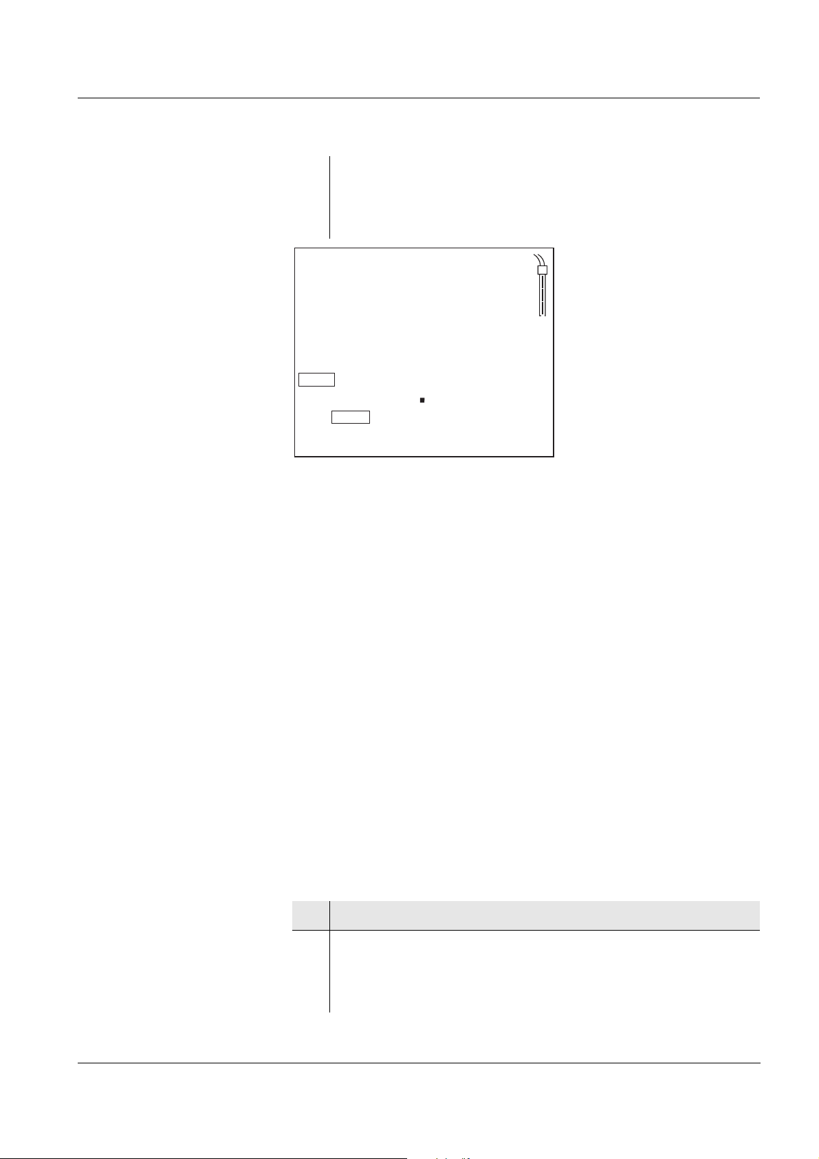
M 545P Operation
2 During the display test, display the calibration data with <CAL>.
The following data is displayed consecutively for 10 seconds
each:
date, zero point, slope.
C
Day.Month
0
30
AutoCal
While the calibration data is being displayed you can:
z press <OK> to display further calibration data
z press <▲><▼> to switch over the unit of the zero point (ASY)
z press <▲><▼> to switch over the unit of the slope (SLO)
z press <CAL
_> to download the calibration record to the
L
A
9
(date, zero point, slope)
(while the zero point is being displayed)
(while the slope is being displayed)
interface
Download to display via
calibration menu
ba75564e03 02/2007
1 Press <CAL>.
2 Press <CAL
The following data is displayed consecutively for 10 seconds
each:
date, asymmetry, slope.
_> to display the calibration data.
39
Page 40

Operation M 545P
While the calibration data is being displayed you can:
z press <OK> to display further calibration data
(date, zero point, slope)
z press <▲><▼> to switch over the unit of the zero point (ASY)
(while the zero point is being displayed)
z press <▲><▼> to switch over the unit of the slope (SLO)
(while the slope is being displayed)
z press <CAL
_> to download the calibration record to the
interface
40
ba75564e03 02/2007
Page 41

M 545P Operation
4.6 Transmitting data
The meter has an RS232 interface (serial interface). Via the interface,
you can transmit data to a PC or printer and update the meter software.
Note
The relevant interface cable has to be connected if you want to
download data to the interface (RS232).
Caution
The interface is not galvanically isolated.
When connecting an earthed PC/printer, measurements cannot be
performed in earthed media as incorrect values would result.
4.6.1 Options for data transmission
The following table shows which data are transmitted to the interface in
which way:
Data Control Operation / description
Current measured
values
Stored measured
values
Calibration records manual z Without display indication
manual z With <OK>.
automatic, at
intervals
automatic z After each measurement
manual z All datasets
z With <AR
can set the transmission
interval (Int.2) (section
4.6.2).
z Simultaneously with every
automatic storage process
(Int.1)
(see section 4.6.2).
with AutoRead.
(see section 4.6.3)
(see section 4.5.5).
z During display indication
with <CAL
(see section 4.5.5).
_>. Then you
_>
ba75564e03 02/2007
automatic z At the end of a calibration
procedure.
41
Page 42

Operation M 545P
4.6.2 Automatically downloading measurement datasets at intervals
In order to automatically download to the interface measured values at
certain time intervals, set the download interval (Int.2).
Setting the download
interval
The default setting for the download interval (Int 2) is OFF.
To switch the function on, set an interval (5 s, 10 s, 30 s, 1 min, 5 min,
10 min, 15 min, 30 min, 60 min):
1 Press <AR_> to open the setting of the Int.2 interval.
2 If necessary, set an interval with <▲><▼>.
3 Close the setting with <OK>.
The download to the interface takes place at the specified
interval.
4.6.3 Downloading stored measurement datasets
1 Open the memory menu with <RCL>.
2 If necessary, scroll with <RCL> until Sto Prt is displayed.
3 Press <OK> to download the calibration data to the interface.
42
4.6.4 Downloading calibration data
1 Open the memory menu with <RCL>.
2 If necessary, scroll with <RCL> until CAL Prt is displayed.
3 Press <OK> to download the calibration data to the interface.
4.6.5 RS232 interface
ba75564e03 02/2007
Page 43

M 545P Operation
1 Connect the interface to the PC or printer via a suitable cable.
2 Set up the following transmission data on the PC/printer:
– Baud rate: selectable from 1200, 2400, 4800, 9600,
– Handshake: RTS/CTS + Xon/Xoff
– PC only:
– Parity: none
– Data bits: 8
– Stop bits: 1
Socket assignment
(RS232)
4
5
RS 232
3
2
6
1
2 RxD
3 TxD
4 not used
5 SGnd
6 CTS
1 not used
ba75564e03 02/2007
43
Page 44

Operation M 545P
4.7 Settings
You can adapt the meter to your individual requirements. The settings
are done in the following menus:
z System settings (<OK
– Baud rate (Baud)
– Switch-off interval (t.Off)
– Date (Day.Month)
– Date (Year)
– Time (Time)
z Calibration and measurement settings (<MODE
– Number of the buffer set for pH calibration (Set 1 ... 16)
– Display of the buffer during calibration
(pH nominal value or measured voltage value in mV)
– Unit of the value for the slope (mV/pH or %)
– Unit of the value for the zero point (mV, pH)
– Resolution (Hi, Lo)
– Temperature unit (°C / °F)
– Calibration interval (Int.C [0 ... 999])
z Setting for automatic storage (<STO
– AutoStore interval (Int.1)
_>)
_>)
_>)
z Setting for data download (<AR
– Data download interval (Int.2)
Note
You can exit the setting menu at any time by pressing <MODE>.
Settings already modified and confirmed with <OK> are stored.
_>)
44
ba75564e03 02/2007
Page 45

M 545P Operation
4.7.1 System settings
The default setting is printed in bold.
Baud rate (Baud) 1200, 2400, 4800, 9600
Switch-off interval (t.Off) 10, 20, 30, 40, 50 min,
1, 2, 3, 4, 5, 10, 15, 20, 24 h
Date (Day.Month)Any
Date (Year) Any
Time (Time)Any
1 Open the menu for system settings with <OK_>.
The first system setting is displayed.
Baud rate (Baud)
Switch-off interval (t.Off)
Baud
8
40
2 Set the required baud rate with <▲><▼> .
3 Confirm with <OK>.
t.OFF, the setting of the switch-off interval is displayed.
0
ba75564e03 02/2007
Time
O
t
00
f
1
f
0
45
Page 46

Operation M 545P
4 Set the switch-off interval with <▲><▼>.
5 Confirm with <OK>.
Day.Month, the setting of the date is displayed.
The day display flashes.
Date and time
Day.Month
0
30
3
6 Set the date of the current day with <▲><▼> .
7 Confirm with <OK>.
The month display flashes.
8 Set the current month with <▲><▼> .
9 Confirm with <OK>.
Ident, the setting of the year is displayed.
10 Set the year with <▲><▼> .
11 Confirm with <OK>.
The setting of the time is displayed.
The hour display flashes.
12 Set the current hour with <▲><▼> .
13 Confirm with <OK>.
The minute display flashes.
14 Set the current minute with <▲><▼> .
15 Confirm with <OK>.
The system settings are completed.
The meter switches to the measuring mode.
46
ba75564e03 02/2007
Page 47
M 545P Operation
4.7.2 Measurement settings
These settings apply to calibration and measurement (the default
setting is printed in bold).
Number of the buffer set for pH
calibration (SET)
Display during calibration (BUFFER) pH (buffer nominal value),
Unit of the value for the slope (SLO) mV/pH, %
1 ... 16
U (electrode voltage)
Buffer set for pH
calibration
(SET)
Unit of the value for the zero point
(ASY)
Resolution (pH display) Hi (high), Lo (low)
Temperature unit (UnIt) °C, °F
Calibration interval (Int.C) 0 ... 7 ... 999 d
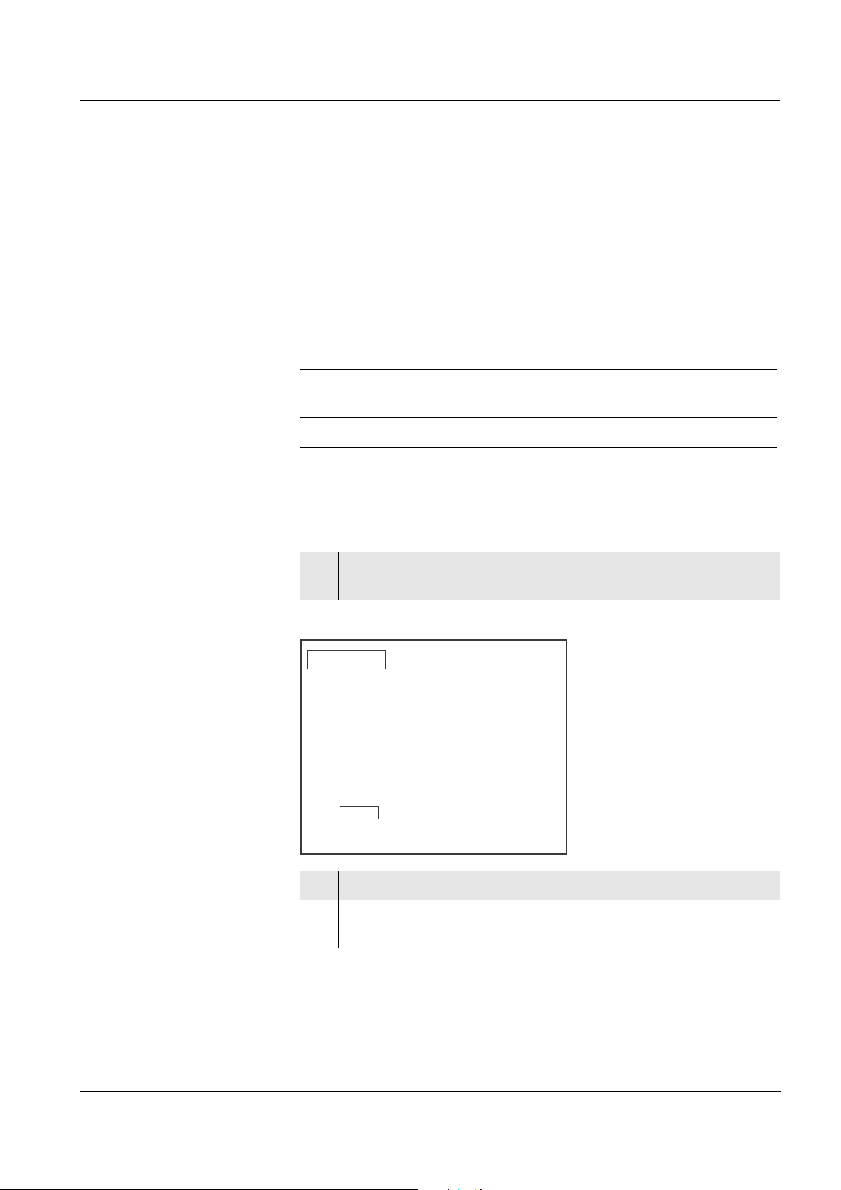
1 Open the menu for measurement settings with <MODE_>.
Set 1 ... 16, the specified buffer set is displayed.
SET
mV, pH
1
ba75564e03 02/2007
AutoCal
2 Using <▲><▼>, select a buffer set, Set 1 ... 16.
3 Confirm with <OK>.
bUFF, the setting of the display during calibration is displayed.
47
Page 48

Operation M 545P
Display during
calibration
(bUFF)
pH
Unit of the value for the
slope
(SLO)
F
H
L
F
O
mV/pH
U
b
p
AutoCal
4 Using <▲><▼>, select the pH or U display during calibration.
5 Confirm with <OK>.
SLO, the unit of the value for the slope (mV/pH or %) is
displayed.
pH
S
48
6 Using <▲><▼>, select the unit for the slope.
7 Confirm with <OK>.
ASY, the unit of the value for the zero point (mV or pH) is
displayed.
ba75564e03 02/2007
Page 49

M 545P Operation
Unit of the value for the
zero point
(ASY)
8 Using <▲><▼>, select the unit for the zero point.
9 Confirm with <OK>.
rES, the setting of the resolution is displayed.
pH
A
S
Y
mV
Resolution
(rES)
pH
e
H
s
I
r
10 Using <▲><▼>, toggle between Hi and Lo.
11 Confirm with <OK>.
Unit, the setting of the unit of the temperature value is
displayed.
ba75564e03 02/2007
49
Page 50

Operation M 545P
Temperature unit (Unit)
Calibration
interval
(Int.C)
i
o
T
t
C
C
TP
°
C
n
U
12 Using <▲><▼>, toggle between °C and °F.
13 Confirm with <OK>.
Int.C, the setting of the calibration interval is displayed.
N
I
Time
7d
AutoCal
14 Set the interval with <▲><▼>.
15 Confirm with <OK>.
The measurement settings are completed.
The meter switches to the measuring mode.
50
ba75564e03 02/2007
Page 51
M 545P Operation
4.7.3 Interval for automatic storing (AutoStore)
After setting the interval for automatic storing the current measurement
dataset is stored at the specified interval.
AutoStore interval (Int.1) OFF, 5 s, 10 s, 30 s, 1 min,
5 min, 10 min, 15 min, 30 min, 60 min
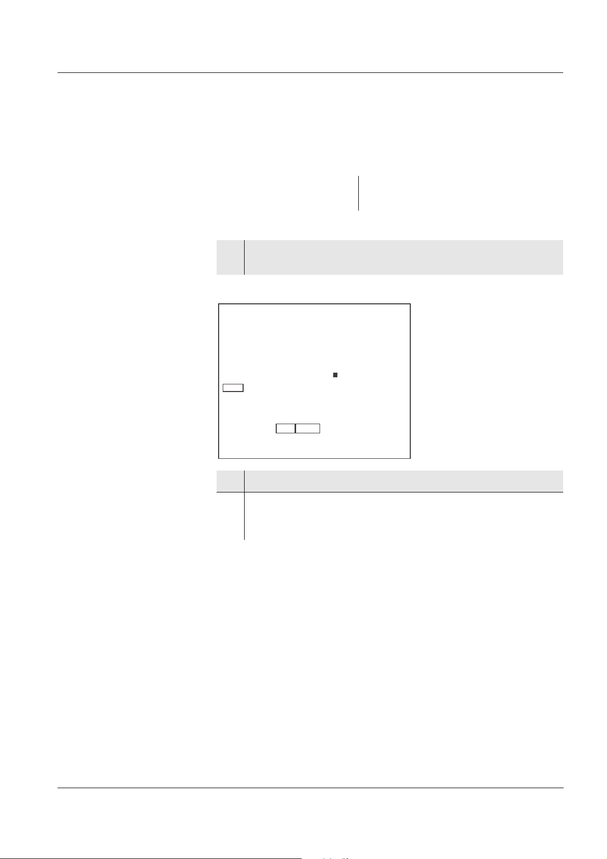
1 Press <STO_> to open the setting for the storage interval.
Int.1, the setting of the storage interval is displayed.
AutoStore
interval
t
0
1
0
n
I
Time
1
Auto
Store
2 Press <▲><▼> to select an interval.
3 Confirm with <OK>.
The setting of the storage interval is completed.
The meter switches to the measuring mode.
ba75564e03 02/2007
51
Page 52
Operation M 545P
4.7.4 Interval for automatic data transmission
The interval for automatic data transmission serves to transmit the
current measurement dataset to the interface at the specified interval.
Data transmission
interval
Data transmission interval
(Int.2)
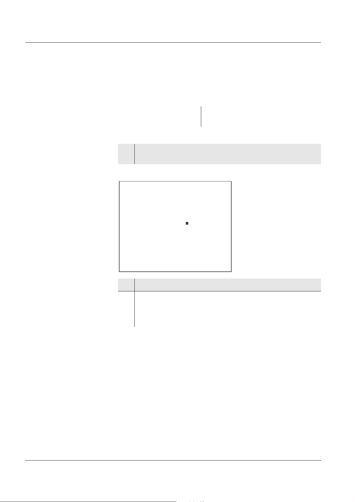
1 Press <AR_> to open the setting for the transmission interval.
Int.2, the setting of the transmission interval is displayed.
N
I
T
5
2 Press <▲><▼> to select an interval.
OFF, 5 s, 10 s, 30 s, 1 min,
5 min, 10 min, 15 min, 30 min, 60 min
2
0
3 Confirm with <OK>.
The setting of the interval for data transmission to the interface
is completed.
The meter switches to the measuring mode.
52
ba75564e03 02/2007
Page 53
M 545P Operation
4.8 Reset
4.8.1 Resetting calibration values
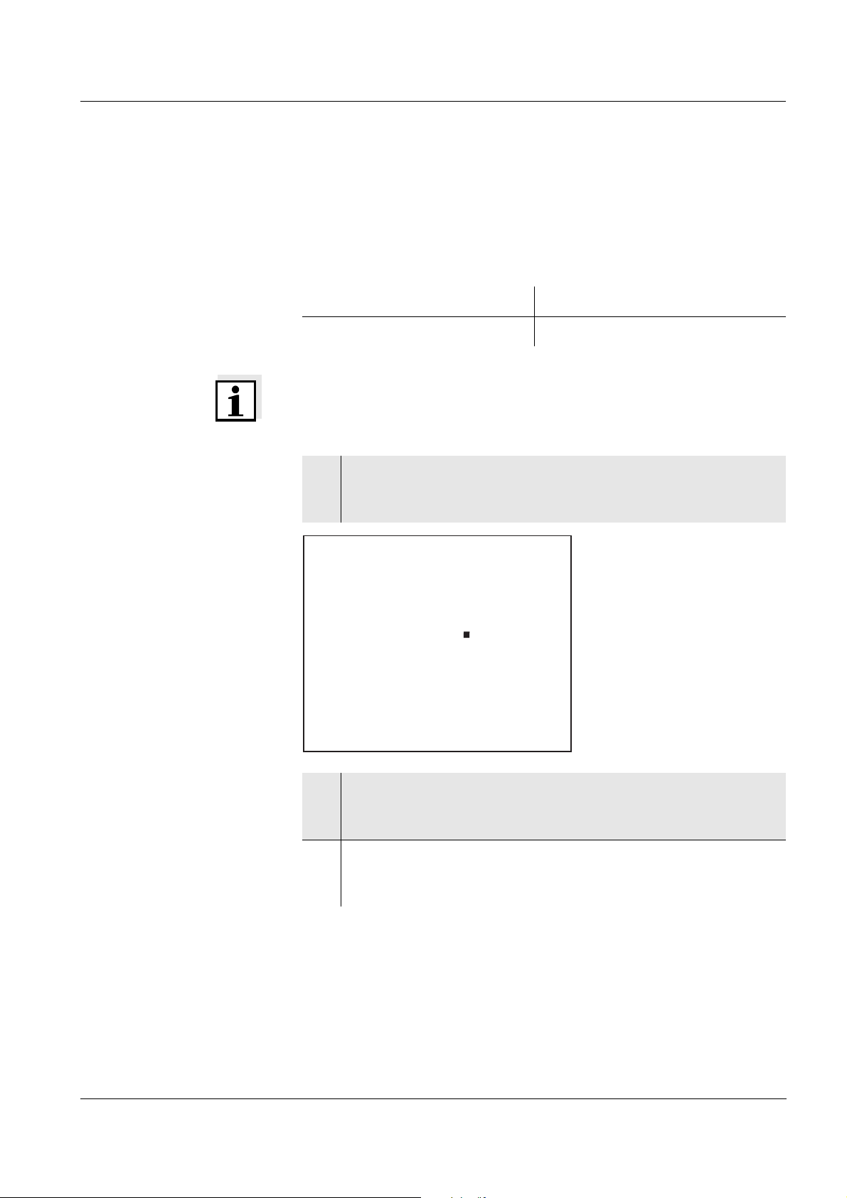
This function resets the calibration values to the default condition. All
other meter settings are retained.
Calibration values in the
default condition
Resetting calibration
values
Zero point pH 7.000 (0 mV)
Slope 100 % (-59.16 mV/pH)
Note
The measuring system is not calibrated after a reset. Before
measuring, recalibrate the meter.
1 Press <On/Off_> to open the menu for the reset of the
calibration data.
Ini.C is displayed.
pH
I
n
I
n
C
o
ba75564e03 02/2007
2 Press <▲><▼> to display no or YES.
YES: Reset the calibration values.
no: Retain the calibration values.
3 Confirm with <OK>.
The menu is finished.
The meter switches to the measuring mode.
53
Page 54
Operation M 545P
4.8.2 Resetting meter settings
This function resets to the default condition all meter settings. The
relevant values are given in the following sections:
System settings section 4.7.1
Measurement settings section 4.7.2
Resetting the meter
settings
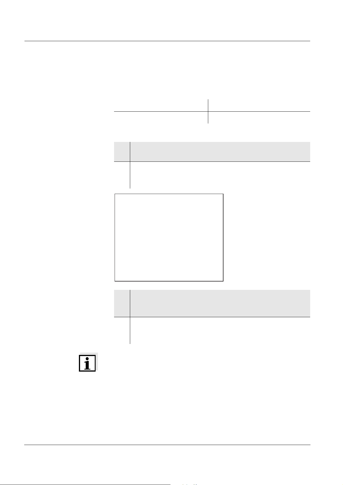
1 Switch on the meter with <On/Off>.
The display test appears briefly on the display.
2 During the display test, press <MODE> to open the menu for
the reset of the meter settings.
Init is displayed.
i
n
t
o
n
I
3 Press <▲><▼> to display no or YES.
YES: Reset the meter settings.
no: Retain the meter settings.
54
4 Confirm with <OK>.
The menu is finished.
The meter switches to the measuring mode.
Note
The measuring system is not calibrated after a reset. Before
measuring, recalibrate the meter.
ba75564e03 02/2007
Page 55
M 545P Maintenance, cleaning, disposal
5 Maintenance, cleaning, disposal
5.1 Maintenance
The only maintenance activity required is replacing the batteries.
Note
For maintenance of the electrodes refer to the relevant operating
manuals.
5.1.1 Replacing the batteries
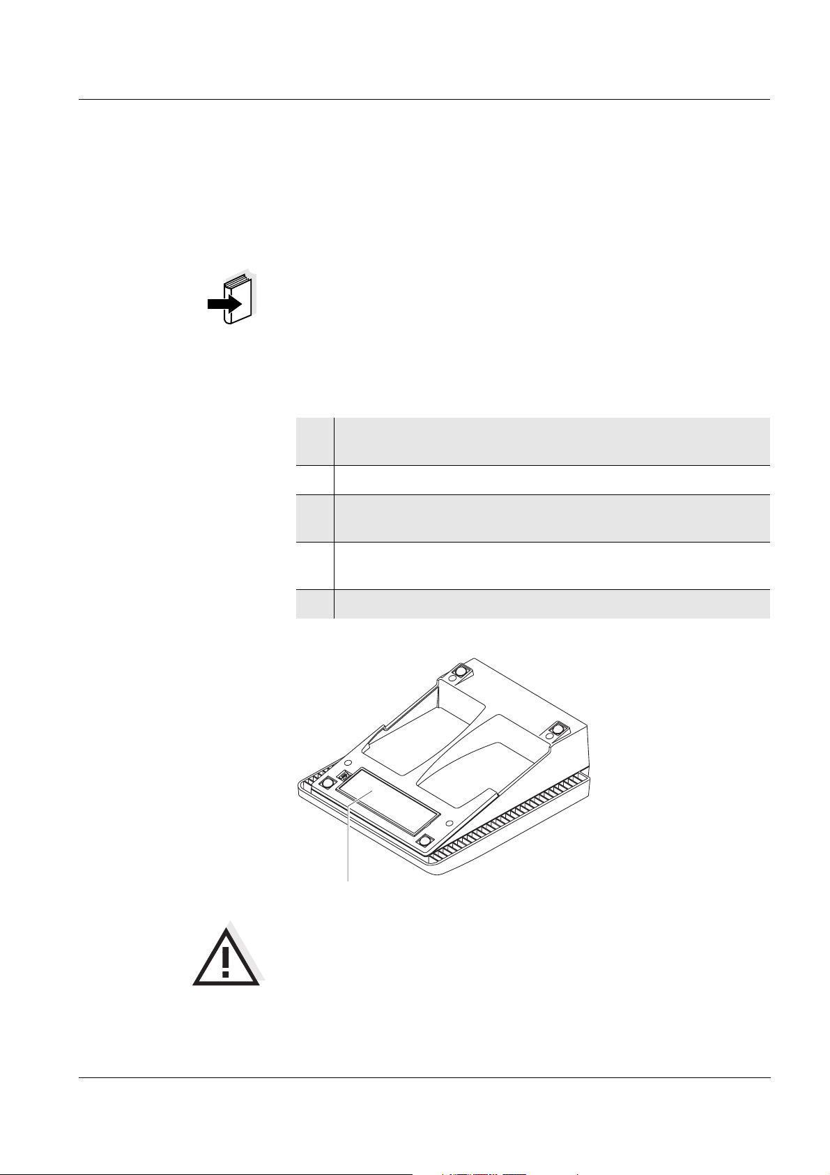
1 Open the battery compartment (1) on the underside of the
meter.
2 Remove the four batteries from the battery compartment.
3 Place four new batteries (type Mignon AA) in the battery
compartment.
4 Close the battery compartment (1).
The date (day) flashes on the display.
5 Set the date and time according to section 4.7.1.
1
ba75564e03 02/2007
Caution
Make sure that the poles of the batteries are the right way round.
The
± signs on the batteries must correspond to the ± signs in the
battery compartment.
Only use leakproof alkaline manganese batteries.
55
Page 56

Maintenance, cleaning, disposal M 545P
5.2 Cleaning
Occasionally wipe the outside of the meter with a damp, lint-free cloth.
Disinfect the housing with isopropanol as required.
Caution
The housing is made of synthetic material (ABS). Thus, avoid
contact with acetone or similar detergents that contain solvents.
Remove any splashes immediately.
5.3 Packing
This meter is sent out in a protective transport packing.
We recommend: Keep the packing material. The original packing
protects the meter against damage during transport.
56
ba75564e03 02/2007
Page 57

M 545P What to do if...
6 What to do if...
Error message
Err1
Error message
Err2
Cause Remedy
pH electrode:
– Measured value outside the
measuring range
– Air bubble in front of the
diaphragm
– Air in the diaphragm – Extract air or moisten
– Cable broken – Replace electrode
– Gel electrolyte dried out – Replace electrode
Cause Remedy
– No electrode connected – Connect electrode
– Setting time during calibration
too long
– Use a suitable electrode
– Remove air bubble
diaphragm
– Adjust temperature if
necessary
– Recalibrate
Error message
Err4
Error message
CalError
Cause Remedy
– Temperature not stable during
calibration.
Cause Remedy
pH electrode:
– The values determined for zero
point and slope of the electrode
are outside the allowed limits.
– Diaphragm contaminated – Clean diaphragm
– Electrode broken – Replace electrode
– Adjust temperature if
necessary
– Recalibrate
– Recalibrate
ba75564e03 02/2007
57
Page 58

What to do if... M 545P
Cause Remedy
Buffer solutions
– Incorrect buffer solutions – Change calibration
procedure
– Buffer solutions too old – Use only once.
Note the shelf life
– Buffer solutions depleted – Change solutions
No stable measured
Cause Remedy
value
pH electrode:
– Diaphragm contaminated – Clean diaphragm
– Membrane contaminated – Clean membrane
Sensor symbol flashes
Test sample:
– pH value not stable – Measure with air excluded if
necessary
– Temperature not stable – Adjust temperature if
necessary
Electrode + test sample:
– Conductivity too low – Use a suitable electrode
– Temperature too high – Use a suitable electrode
– Organic liquids – Use a suitable electrode
Cause Remedy
– Calibration interval expired – Recalibrate the measuring
system
58
Display,
LoBat
Cause Remedy
– Batteries almost empty – Replace the batteries (see
section 5.1 M
AINTENANCE)
ba75564e03 02/2007
Page 59

M 545P What to do if...
Display
to
Obviously incorrect
measured values
Meter does not react to
keystroke
Cause Remedy
– Time-out of the interface – Check the meter that is
connected
Cause Remedy
pH electrode:
– pH electrode unsuitable – Use a suitable electrode
– Temperature difference
between buffer and test sample
– Adjust temperature of buffer
or sample solutions
too high
– Measurement procedure not
– Follow special procedure
suitable
Cause Remedy
– Operating condition undefined
or EMC load unallowed
– Processor reset:
Press and hold the <AR>
key and switch the meter on
You want to know which
software
version is in the
instrument
Message StoFull
Cause Remedy
– E. g., a question by the service
department
– Switch on the meter.
During the display test,
display the software version
with <OK>.
Cause Remedy
– All 800 memory locations are
full
– Output data memory and
clear data memory
ba75564e03 02/2007
59
Page 60

What to do if... M 545P
60
ba75564e03 02/2007
Page 61

M 545P Technical data
7 Technical data
7.1 General data
Dimensions approx. 240 x 190 x 80 mm
Weight approx. 1.0 kg (without power pack, without stand)
Mechanical structure Type of protection IP 43
Electrical safety Protective class III
Test certificates cETLus
Ambient
conditions
Power
supply
Serial interface Baud rate adjustable: 1200, 2400, 4800, 9600 Baud
Storage - 25 °C ... + 65 °C
Operation 0 °C ... + 55 °C
Climatic class 2
Batteries 4 x 1.5 V alkali-manganese batteries, Type
AA
Operational life Approx. 1000 operating hours
Power pack
(charging device)
Type RS232, bidirectional
Data bits 8
Stop bits 2
Parity None
FRIWO FW7555M/09, 15.1432.500-00
Friwo Part. No. 1883259
Input: 100 ... 240 V ~ / 50 ... 60 Hz / 400 mA
Output: 9 V = / 1.5 A
Connection max. overvoltage category II
Primary plugs contained in the scope of
delivery: Euro, US, UK and Australian.
Guidelines
and norms used
ba75564e03 02/2007
Handshake RTS/CTS+Xon/Xoff
EMC EC guideline 89/336/EEC
EN 61326
EN 61000-3-2
EN 61000-3-3
FCC Class A
61
Page 62

Technical data M 545P
Meter safety EEC guideline 73/23/EEC
EN 61010-1
ANSI/UL 61010-1; Issued 2004/07/12 Ed: 2,
Rev.: 2005/07/22
CAN/CSA-C22.2 No. 61010-1
Climatic class VDI/VDE 3540
IP protection EN 60529
FCC Class A Equipment Statement
Note: This equipment has been tested and found to comply with
the limits for a Class A digital device, pursuant to Part 15 of the
FCC Rules. These limits are designed to provide reasonable
protection against harmful interference when the equipment is
operated in a commercial environment. This equipment
generates, uses, and can radiate radio frequency energy and, if
not installed and used in accordance with the instruction manual,
may cause harmful interference to radio communications.
Operation of this equipment in a residential area is likely to cause
harmful interference in which case the user will be required to
correct the interference at his own expense.
62
ba75564e03 02/2007
Page 63

M 545P Technical data
7.2 Measuring ranges, resolution, accuracy
Measuring ranges,
resolution
Variable Measuring range Resolution
pH - 2.000 ... + 19.999
- 2.00 ... + 19.99
U [mV] - 999.9 ... + 999.9
- 2000 ... + 2000
0.001
0.01
0.1
1
T [°C] - 5.0 ... + 105.0 0.1
T [°F] 23.0 ... + 221.0 0.1
Manual
temperature input
Variable Range Increment
T
T
[°C] - 5 ... + 125 1
manual
[°F] 23 ... + 257 1
manual
Accuracy (± 1 digit) Variable Accuracy Test sample temperature
pH / range *
- 2.000 ... + 19.999 ± 0.005 + 15 °C ... + 35 °C
- 2.00 ... + 19.99 ± 0.01 + 15 °C ... + 35 °C
U [mV] / range
- 999.9 ... + 999.9 ± 0.3 + 15 °C ... + 35 °C
- 2000 ... + 2000 ± 1 + 15 °C ... + 35 °C
T [°C] / temperature sensor
NTC 30 ± 0.1
PT 1000 ± 0.3
* when measuring in a range of ± 2 pH around a calibration point
Note
The accuracy values specified here apply exclusively to the meter. The
accuracy of the electrodes and buffer solutions has to be taken into
account additionally.
ba75564e03 02/2007
63
Page 64

Technical data M 545P
64
ba75564e03 02/2007
Page 65

M 545P Lists
8Lists
This chapter provides additional information and orientation aids.
Abbreviations The list of abbreviations explains abbreviations that appear on the
display or when dealing with the meter.
Specialist terms The glossary briefly explains the meaning of the specialist terms.
However, terms that should already be familiar to the target group are
not described here.
Trademarks used The list comprises the trademarks used in the present document and
their owners.
Index The index helps you to find the topics that you are looking for.
ba75564e03 02/2007
65
Page 66

Lists M 545P
Abbreviations
°C Temperature unit °Celsius
°F Temperature unit, °Fahrenheit
AR AutoRead (drift control)
ASY Zero point (asymmetry)
AutoCal Automatic calibration using a selected buffer set
Cal Calibration
CalError Error message (see W
HAT TO DO IF...)
disp Display
Data memory is displayed
Err1 Overflow
Display range exceeded
Err2 Overflow
Display range exceeded
Err4 Display range exceeded
InI Initialization
Resets individual basic functions to the status they
had on delivery
LoBat Low Battery (batteries almost empty)
mV Voltage unit
mV/pH Unit of the electrode slope
pH pH value
RCL Recall (memory download)
66
S Slope value
SELV Safety Extra Low Voltage
SEr Serial interface
Download of the data memory to the RS 232
SLO Slope (slope on calibration)
Sto Store (memory)
TP Temperature Probe
Temperature measurement active
ba75564e03 02/2007
Page 67

M 545P Lists
Glossary
Adjusting To manipulate a measuring system so that the relevant value (e. g. the
displayed value) differs as little as possible from the correct value or
a value that is regarded as correct, or that the difference remains
within the tolerance.
Asymmetry see zero point
AutoRange Name of the automatic selection of the measuring range.
AutoRead Function to control the measured value stability.
Calibration Comparing the value from a measuring system (e. g. the displayed
value) to the correct value or a value that is regarded as correct.
Often, this expression is also used when the measuring system is
adjusted at the same time (see adjusting).
Electromotive force of
an electrode
The electromotive force (voltage) U of the electrode is the measurable
electromotive force of an electrode in a solution. It equals the sum of
all the galvanic voltages of the electrode. Its dependency on the pH
results in the electrode function, which is characterized by the
parameters, slope and zero point.
Junction The junction is a porous body in the housing wall of reference
electrodes or electrolyte bridges. It arranges the electrical contact
between two solutions and makes the electrolyte exchange more
difficult. The expression, junction, is also used for ground or junctionless transitions.
Measured value The measured value is the special value of a measured parameter to
be determined. It is given as a combination of the numerical value and
unit (e. g. 3 m; 0.5 s; 5.2 A; 373.15 K).
Measured variable The measured parameter is the physical dimension determined by
measuring, e. g. pH, conductivity or D.O. concentration.
Molality Molality is the quantity (in Mol) of a dissolved substance in 1000 g
solvent.
ORP voltage The ORP is caused by oxidizing or reducing substances dissolved in
water, if these substances become effective at an electrode surface
(e. g. a gold or platinum surface).
pH value The pH is a measure of the acidic or basic effect of an aqueous
Potentiometry Name of a measuring technique. The signal (depending on the
ba75564e03 02/2007
solution. It corresponds to the negative decadic logarithm of the molal
hydrogen ions activity divided by the unit of the molality. The practical
pH value is the value of a pH measurement.
measured parameter) of the electrode is the electrical potential. The
electrical current remains constant.
Reset Restoring the original condition of all settings of a measuring system.
67
Page 68

Lists M 545P
Resolution Smallest difference between two measured values that can be
displayed by a measuring instrument.
Slope The slope of a linear calibration function.
Standard solution The standard solution is a solution where the measured value is
known by definition. It is used to calibrate a measuring system.
Test sample Designation of the test sample ready to be measured. Normally, a test
sample is made by processing the original sample. The test sample
and original sample are identical if the test sample was not processed.
Zero point The zero point of a pH electrode is the pH value at which the
electromotive force of the pH electrode at a specified temperature is
zero. Normally, this is at 25 °C.
68
ba75564e03 02/2007
Page 69

M 545P Lists
Trademarks used
Trademark Owner of the trademark
Merck Merck KGaA
Mettler Toledo Mettler Toledo
Fisher Fisher Scientific Company
Fluka Fluka AG
Radiometer Radiometer
Baker Mallinckrodt Baker, Inc.
Metrohm Metrohm AG
Beckman Beckman Instruments, Inc.
Hamilton Hamilton Company Corporation
Precisa Precisa Instruments AG
Windows Microsoft Corporation
ba75564e03 02/2007
69
Page 70

Lists M 545P
70
ba75564e03 02/2007
Page 71

M 545P Lists
Index
A
Authorized use . . . . . . . . . . . . . . . . . . . . . . 12
AutoCal . . . . . . . . . . . . . . . . . . . . . . . . . . . 28
AutoRead . . . . . . . . . . . . . . . . . . . . . . . . . . 20
B
Battery compartment . . . . . . . . . . . . . . . . . 55
Baud rate setting . . . . . . . . . . . . . . . . . . . . 45
C
Calibration . . . . . . . . . . . . . . . . . . . . . . . . . 22
Calibration evaluation
pH . . . . . . . . . . . . . . . . . . . . . . . . . . . . 25
Calibration interval . . . . . . . . . . . . . . . . . . . 27
Calibration points
pH . . . . . . . . . . . . . . . . . . . . . . . . . . . . 24
ConCal . . . . . . . . . . . . . . . . . . . . . . . . . 24, 31
Connect the power pack . . . . . . . . . . . . . . 15
D
Dataset . . . . . . . . . . . . . . . . . . . . . . . . . . . . 33
Display . . . . . . . . . . . . . . . . . . . . . . . . . . . . . 9
Drift control . . . . . . . . . . . . . . . . . . . . . . . . . 20
E
Energy saving feature . . . . . . . . . . . . . . . . 17
O
Operation location . . . . . . . . . . . . . . . . . . . 17
Operational safety . . . . . . . . . . . . . . . . . . . 12
ORP electrode . . . . . . . . . . . . . . . . . . . . . . 21
ORP voltage . . . . . . . . . . . . . . . . . . . . . . . 21
P
pH buffer sets . . . . . . . . . . . . . . . . . . . . . . 22
Precautions . . . . . . . . . . . . . . . . . . . . . . . . 11
Print . . . . . . . . . . . . . . . . . . . . . . . . . . . . . . 41
R
Reset . . . . . . . . . . . . . . . . . . . . . . . . . . . . . 53
All meter settings . . . . . . . . . . . . . . . . . 54
Calibration values . . . . . . . . . . . . . . . . 53
Resolution setting . . . . . . . . . . . . . 47, 48, 49
S
Safety . . . . . . . . . . . . . . . . . . . . . . . . . . . . . 11
Scope of delivery . . . . . . . . . . . . . . . . . . . . 15
Setting the date . . . . . . . . . . . . . . . . . . 15, 46
Setting the time . . . . . . . . . . . . . . . . . . 15, 46
Single-point calibration . . . . . . . . . 24, 29, 32
Slope
pH . . . . . . . . . . . . . . . . . . . . . . . . . . . . 22
Socket field . . . . . . . . . . . . . . . . . . . . . . . . 10
Storage interval . . . . . . . . . . . . . . . . . . . . . 35
F
Firmware update . . . . . . . . . . . . . . . . . . . . 73
I
Initial commissioning . . . . . . . . . . . . . . . . . 15
Interval
Calibration . . . . . . . . . . . . . . . . . . . . . . 27
K
Keys . . . . . . . . . . . . . . . . . . . . . . . . . . . . . . . 8
L
LoBat . . . . . . . . . . . . . . . . . . . . . . . . . . . . . 58
M
Measurement accuracy . . . . . . . . . . . . . . . 27
ba75564e03 02/2007
T
Temperature sensor . . . . . . . . . . . . . . . . . 19
Two-point calibration . . . . . . . . . . . . . . 24, 29
ConCal . . . . . . . . . . . . . . . . . . . . . . . . . 31
Z
Zero point of the pH electrode . . . . . . . . . . 22
71
Page 72

Lists M545P
72
ba75564e03 02/2007
Page 73

M 545P
Appendix: Firmware update
General information With theUpdate_Labxxx_MxxxP program and a PC you can update the
firmware of the M 545P to the newest version.
For the update, you can connect the meter to a PC via the RS232
interface.
For the update via the RS232 interface, the following is required:
z a free RS232 interface on your PC
z an RS232 cable (interface cable).
Program installation Install the firmware update program on your PC with the
"Install_Update_Labxxx_MxxxP_Vx_yy_English.exe" installation
program.
Program start Start the "Update_Labxxx_MxxxP" program from the Windows start
menu. The selected interface is displayed on the left side of the status
bar at the lower edge of the window.
You can change the language via the language menu.
Firmware update Proceed as follows:
1 Using the interface cable, connect the M 545P to the serial
interface (COM port) of the PC.
2 Make sure the M 545P is switched on.
3 To start the update process click the OK button.
The program automatically recognizes the used interface.
4 To go on, follow the instruction of the program.
During the programming process, a corresponding message
and a progress bar (in %) appear.
The programming process takes approx. two minutes.
A terminatory message is displayed after a successful
programming process. The firmware update is now completed.
5 Disconnect the meter from the PC.
The meter is ready for operation.
After switching the meter off and on you can check whether the meter
has taken over the new software version (see page 59).
ba75564e03 02/2007
73
Page 74

M 545P
74
ba75564e03 02/2007
Page 75

Nova Analytics Corp.
Woburn, MA USA 01801
866 664 6682
www.nova-ph.com
 Loading...