

Page 1
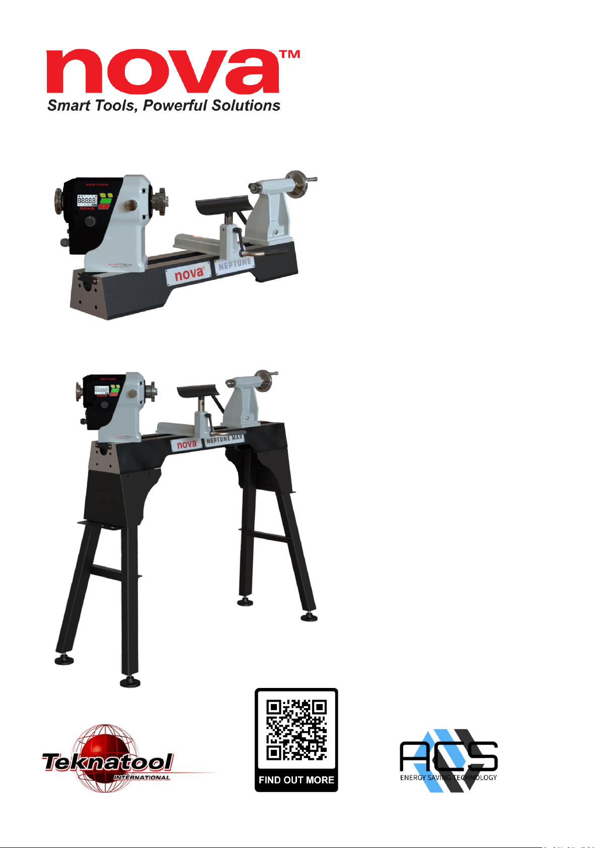
OPERATION MANUAL
Neptune DVR 15” Lathe
USA & Canada SKU: 55700
New Zealand & Australia SKU: 55701
UK SKU: 55702
Europe SKU: 55703
Neptune Max DVR 15” Lathe
USA& Canada SKU: 55710
New Zealand & Australia SKU: 55711
UK SKU: 55712
Europe SKU: 55713
Revision 25 October 2023
Page 2

2
128-01-2310
128-0621-003
WELCOME:
Thank you for choosing the NOVA Neptune 15” DVR Lathe Series and welcome to the NOVA product family.
Your choice shows that you want the best for your woodturning and you recognize the superb DVR drive
technology powered by STRIATECH and the host of other unique features the NOVA DVR Lathe has to offer.
We strive to achieve the best value for your money – providing quality, innovative features, a wide range of
accessories – plus comprehensive, ongoing support (latest manuals downloadable from our website,
newsletters, projects, etc.). We are only a phone call or email away with technical advice or assistance on the
operation of your lathe or your woodturning queries.
Please feel free to contact us about any aspect of our products or service – we regard our customers as our best
development and improvement team – we would love to hear from you!
Once again, welcome to the “NOVA Family.” We trust that you enjoy our products and hope they enhance the
pleasure you experience from the wonderful craft of woodturning!
Best Regards,
Brian Latimer
Marketing Director Teknatool International Ltd
Contact
Teknatool International Ltd
Phone: (+64) 9 477 5600
Teknatool USA
Phone: 727-954-3433
Customer Solutions
For all worldwide Inquiries, Repairs or Services (issues must be in writing)
Contact us at: https://www.teknatool.com/support/
Or you can contact the retailer where you purchased your NOVA Neptune DVR 15” DVR Lathe, for contact
details please see our website www.teknatool.com
Page 3

3
128-01-2310
128-0621-003
Table of Contents
Contact .................................................................................................................................................................................... 2
Table of Contents ................................................................................................................................................................... 3
1.General Safety Rules ........................................................................................................................................................... 4
2.NOVA Neptune/Neptune Max DVR 15” DVR Lathe Features & Specification .................................................................. 5
3.Shipping Contents ............................................................................................................................................................... 8
4.Setup and Assembling the Lathe ...................................................................................................................................... 10
4.1 Unpacking and Preparing the Lathe ................................................................................................................ 11
4.2 Lathe Installation ........................................................................................................................................... 11
4.2.1 Determine Mode of Turning (Neptune Model) ................................................................................................................ 11
4.2.2 Assembly Bed to Stand (Neptune Max Model) ................................................................................................................ 14
4.2.3 Assemble the Toolrest and Tailstock ................................................................................................................................ 15
4.2.4 Mounting the Headstock, Toolrest and Tailstock onto the Bed ....................................................................................... 15
4.3 Positioning the Headstock on the Bed ............................................................................................................ 17
4.4 Spindle Index/Lock......................................................................................................................................... 18
4.5 Toolrest ......................................................................................................................................................... 19
4.6 Tailstock ........................................................................................................................................................ 19
4.7 Lathe Alignment ............................................................................................................................................ 20
4.8 Mounting a Faceplate or a Chuck .................................................................................................................... 22
4.8.1 Mounting on the Standard Version Spindle ..................................................................................................................... 22
4.8.2 Mounting on the European Version Spindle .................................................................................................................... 23
4.9 Removal of Faceplate and Handwheel ............................................................................................................ 24
5. Connecting to Power ........................................................................................................................................................ 25
5.1 Ground Fault Interrupters (GFI) ...................................................................................................................... 26
5.2 Input Voltage Selection .................................................................................................................................. 26
6. Lathe Operation on HMI Panel - Human Machine Interface Panel ................................................................................ 27
6.1 HMI introduction ........................................................................................................................................... 27
6.2 General HMI Operations ................................................................................................................................ 28
7. Maintenance ..................................................................................................................................................................... 34
8. Troubleshooting ............................................................................................................................................................... 35
9. Teknatool Warranty ......................................................................................................................................................... 36
10. NOVA DVR Lathe Breakdown ........................................................................................................................................ 37
11. Optional Accessories ...................................................................................................................................................... 43
12.NOVA DVR Wiring Diagram ............................................................................................................................................ 44
Page 4

4
128-01-2310
128-0621-003
1.General Safety Rules
WARNING
Failure to follow these rules may result in serious personal injury or death.
❖ IMPORTANT: Before switching the lathe on, ALWAYS check the machine for the correct setting and speed
1. BEFORE OPERATING THE TOOL READ THE
MANUAL! Learn the machine’s application and
limitations, plus the specific hazards particular to it.
2. ALWAYS USE SAFETY GLASSES (must be ANSI
approved) Everyday eyeglasses usually are only impact
resistant and safety glasses only protect eyes. A full-face
shield will protect the eyes and face. Also use face or dust
mask if sanding operation is dusty.
3. WEAR PROPER APPAREL. Do not wear loose clothing,
gloves, neckties, rings, bracelets or other jewelry which
may get caught in moving parts. Nonslip footwear is
recommended. Wear protective hair covering to contain
long hair.
4. USE EAR PROTECTORS. Use earmuffs for extended
period of operation. Use muffs rated to 103 DBA LEQ (8
hour).
5. DO NOT USE IN DANGEROUS ENVIRONMENT. Do
not use power tools in damp or wet locations or expose
them to rain. Keep work area well lighted. The NOVA DVR
is intended for indoor use only. Failure to do so may void
the warranty.
14. KEEP GUARDS IN PLACE and in working order.
15. USE CORRECT TOOLS. Do not use a tool or attachment to
do a job for which it was not designed.
16. USE RECOMMENDED NOVA ACCESSORIES. The use of
improper accessories may cause hazards.
17. DO NOT FORCE THE TOOL. It will do the job better and be
safer at the rate for which it was designed.
18. MAINTAIN TOOLS IN TOP CONDITION. Keep tools sharp
and clean for best and safest performance. Follow
instructions for lubricating and changing accessories.
19. NEVER STAND ON TOOL. Serious injury could occur if the
tool is tipped or if the cutting tool is accidentally contacted.
20. REMOVE ADJUSTING KEYS AND WRENCHES. Form a
habit of checking to see that keys and adjusting wrenches
are removed from tool before turning it on.
21. DO NOT OVERREACH. Keep proper footing and balance at
all times.
22. DIRECTION OF FEED. Mind the direction of
spindle/chuck/work to ensure a safe environment.
23. PAY ATTENTION TO WORK. Concentrate on your work. If
you become tired or frustrated, leave it for a while and rest.
24. SECURE WORK. Use clamps or a vice to hold work when
practical. Severe injury or death can occur if an object comes
free as it can become a dangerous projectile.
25. CHECK DAMAGED PARTS. Before further use of the tool,
any part that is damaged should be carefully checked to
ensure that it will operate properly and perform its intended
function. Check for alignment of moving parts, binding of
moving parts, mounting, and any other conditions that may
affect its operation. Any damaged part should be properly
repaired or replaced.
26. DRUGS, ALCOHOL, MEDICATION. Do not operate
machine while under the influence of drugs, alcohol, or any
medication.
27. DUST WARNING. The dust generated by certain woods
and wood products can be harmful to your health. Always
operate machinery in well-ventilated areas and provide
means for proper dust removal. Use wood dust collection
systems whenever possible.
28. DO NOT MODIFY OR USE THE LATHE FOR USES
OTHER THAN FOR WHICH IT WAS DESIGNED.
29. CALIFORNIA PROPOSITION 65 – SEE PAGE 45
6. KEEP WORK AREA CLEAN. Cluttered areas/benches
invite accidents. Build-up of sawdust is a fire hazard.
7. KEEP CHILDREN AND VISITORS AWAY. The NOVA
DVR is not recommended for children and ailing persons.
Such personnel and onlookers should be kept a safe
distance from work area.
8. MAKE WORKSHOP CHILDPROOF with locks, master
switches, or by removing starter keys.
9. GROUND ALL TOOLS. If the tool is equipped with a
three-prong plug, it should be plugged into a three-hole
electrical receptacle. If an adapter is used to
accommodate a two-prong receptacle, the adapter plug
must be attached to a known ground. Never remove the
third prong and add surge protection.
10. MAKE SURE TOOL IS DISCONNECTED FROM POWER
SOURCE whilst in service/maintenance mode.
11. DISCONNECT TOOLS FROM WALL SOCKET before
servicing and when changing accessories such as bits,
cutters, fuses, etc.
12. AVOID ACCIDENTAL STARTING. Make sure switch is in
the “Off” position before plugging in power cord.
13. NEVER LEAVE MACHINE RUNNING UNATTENDED.
Do not leave machine unless it is turned off and has come
to a complete stop.
Page 5

5
128-01-2310
128-0621-003
2.NOVA Neptune/Neptune Max DVR 15” DVR Lathe Features & Specification
Feature Name
Description
DIGITAL VARIABLE
RELUCTANCE (DVR)
ELECTRONIC DRIVE
The DVR motor uses smart motor technology to provide an incredibly smooth
and powerful direct drive. The controller constantly monitors the spindle
position and maintains optimal spindle speed. Additional power is added as it
senses extra load from the tool.
POWER TO TURN AND BURN
220~240V / 10A 1.1KW (1.5HP)
110-120V / 14A 1.1KW (1.5HP)
Slidable 360° SWIVEL
HEADSTOCK
Slidable headstock
Lock at any position, plus detent locating positions at 0°, 22.5°, 45° and 90°.
High accuracy and easy swivel
SOLID BED STRUCTURE
CAD designed webbing to absorb vibration throughout the bed length.
Exceptional structural strength.
4 FAVOURITE SPEED FUNCTION
Program your favourite speeds for faster and more efficient project set ups.
FLEXIBLE CAPACITY TO MATCH
YOUR PROJECT
- 15" / 381mm Capacity Over Bed
- 20" / 508mm Capacity Outboard (with optional outrigger accessory)
- 18”/ 457 mm Between Centres (Neptune Model)
- 28”/ 711 mm Between Centres (Neptune Max Model)
SAFETY SENSING FEATURE
It senses faults in the setup and advises of safety issues - such as chisel dig in
and spindle lock. It then intelligently shuts down power to the spindle.
ENERGY EFFICIENT
Intelligent (computer controlled) motor only draws as much power as it needs
for the application.
INCREDIBLE VARIABLE SPEED
RANGE
50 RPM – 4,000 RPM.
* 50 RPM is set as a Drying mode ONLY, NOT recommended for turning work.
WARRANTY
* 10 Year Warranty on DVR motor (Bearings, sensor excluded)
* 5 Year Warranty on Motor Electronics and mechanical parts
* Restrictions apply
Page 6

6
128-01-2310
128-0621-003
Neptune Lathe Specifications
Metric
Imperial
Swing Over Bed
381 mm
15”
Distance Between Centres
457 mm
18”
Overall Size
840mm (L) x 425mm (w) x 380mm(H)
33” (L) x 16.7” (w) x 15” (H)
Package Size
900mm (L) x 485mm (w) x 440mm (H)
35.4” (L) x 19.1” (w) x 17.3” (H)
Net Weight
57 Kg ± 2 Kg
125lb ± 4.4 lb
Gross Weight
65 Kg ± 2 Kg
143 lb ± 4.4 lb
Headstock
Spindle Thread
M33 x 3.5 RH ASR*
1”1/4 x 8 TPI
Headstock Spindle Taper
Morse Taper #2 (MT2)
Headstock Swivel
360° With detent positions at: -45°, -22.5°, 0°, 22.5°, 45°, 90°, 180°
Headstock Slidable
Sliding Headstock
Spindle Index lock
24 divisions (15 degrees apart)
Tailstock
Quill Taper
Morse Taper #2 (MT2)
Quill Travel
100mm
3.9”
Hole Through Tailstock
10mm
2/5”
Tool Rest
Length
229mm
9”
Shaft Diameter
25.4mm
1”
Motor Specifications
Motor Type
DVR Direct Drive Smart Motor
Motor Speed Range
50 RPM ~ 40,00 RPM
Input Frequency
50Hz
60 Hz
Motor Power Output
1.1KW (1.5HP)
1.1KW (1.5HP)
Input Voltage
220~240V
110~120V
Input Current
10A (max)
14A (max)
* M33 x 3.5 RH thread ASR spindle only available in European models, The ASR locking ring is excluded from the
standard Neptune lathe package. All other market models will have the 1.25inch x 8 TPI spindle.
Colour Specifications
Jet Black
RAL 9005
R:14 G:14 B:16
Dark Grey
RAL 7021
R:47 G:50 B:52
Light Grey
RAL 7035
R:197 G:199 B:196
Signal White
RAL 9003
R:236 G:236
B:231
Luminous Red
RAL 3024
R:237 G:28 B:36
Page 7
7
128-01-2310
128-0621-003
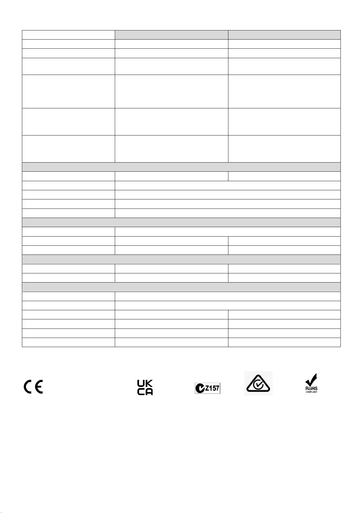
Neptune Max Lathe Specifications
Metric
Imperial
Swing Over Bed
381 mm
15”
Distance Between Centres
711 mm
28”
Overall Size
1292mm (L) x 490mm (w) x
1198mm(H)
50.9” (L) x 19.3” (w) x 47.2” (H)
Package Size
Package 1: 930mm (L) x 420mm (w) x
450mm(H)
Package 2: 935mm (L) x 310mm (w) x
250mm(H)
Package 1: 36.6” (L) x 16.5” (w) x 17.7”
(H)
Package 2: 36.8” (L) x 12.2” (w) x 9.8”
(H)
Net Weight
90 kg ± 2 kg
Package 1: 64 kg ± 2 kg
Package 2: 26 kg ± 2 kg
198.4 lb ± 4.4 lb
Package 1: 141 lb ± 4.4 lb
Package 2: 57.3 lb ± 4.4 lb
Gross Weight
96 kg ± 2 kg
Package 1: 67.5 kg ± 2 kg
Package 2: 28.5 kg ± 2 kg
211.6 lb ± 4.4 lb
Package 1: 148.8 lb ± 4.4 lb
Package 2: 62.8 lb ± 4.4 lb
Headstock
Spindle Thread
M33 x 3.5 RH ASR*
1”1/4 x 8 TPI
Headstock Spindle Taper
Morse Taper #2 (MT2)
Headstock Swivel
360° With detent positions at: -45°, -22.5°, 0°, 22.5°, 45°, 90°, 180°
Headstock Slidable
Sliding Headstock
Spindle Index lock
24 divisions (15 degrees apart)
Tailstock
Quill Taper
Morse Taper #2 (MT2)
Quill Travel
100mm
3.9”
Hole Through Tailstock
10mm
2/5”
Tool Rest
Length
229mm
9”
Shaft Diameter
25.4mm
1”
Motor Specifications
Motor Type
DVR Direct Drive Smart Motor
Motor Speed Range
50 RPM ~ 40,00 RPM
Input Frequency
50Hz
60 Hz
Motor Power Output
1.1KW (1.5HP)
1.1KW (1.5HP)
Input Voltage
220~240V
110~120V
Input Current
10A (max)
14A (max)
* M33 x 3.5 RH thread ASR spindle only available in European models, The ASR locking ring is excluded from the
standard Neptune lathe package. All other market models will have the 1.25inch x 8 TPI spindle.
For Europe, Australasia, and South Africa
Directives this equipment complies with:
Low voltage directive (LVD) 73/23/EEC + 93/68/EEC+2006/95/EC
Machinery directive (MD) 89/392/EEC + 91/368 EEC + 93/68/EEC+2006/42/EC
Electromagnetic compatibility directive (EMCD) 89/336/EEC + 92/31/EEC + 93/68/EEC+2004/108/EC
Harmonized Standards applied in order to verify compliance with Directives: EN 61029-1:2009
Low Voltage Directive and Machinery Directive
EN 55014-1:2007
EN 55014-2:2009
EN 61000-3-2:Ed3 2006
EN 61000-3-3:1995 A1 + A2
Page 8
8
128-01-2310
128-0621-003
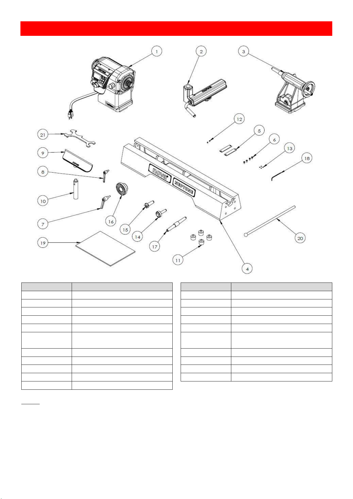
3.Shipping Contents
Neptune Lathe
ITEM NUMBERS
DESCRIPTION
ITEM NUMBERS
DESCRIPTION
1
Headstock Assembly (+HMI)
12
Set Screw M6 x 6mm
2
Toolslide Assembly
13
Soft Washer
3
Tailstock Assembly
14
2MT Live Centre
4
Main Bed 15
2MT Spur Centre
5
Bed End Stopper Plate
16
80mm Face Plate 1 ¼” 8tpi
6
Stopper Plate Screws M5 x 6mm
17
Double Ended Morse Taper –
Acruline Alignment Tool
7
Locking Handle – M10 x 20mm
18
3mm Allen Key
8
Locking Handle – M8 x 20mm
19
Neptune Manual
9
Nova 9" Modular Tool Rest Bar
20
Knock Out Bar
10
Tool Rest Post 1" Shank
21
Universal Spanner
11
Feet Assembly
*Note: EU M33 model with ASR Euro lock but the ASR locking ring needs to be purchased separately.
Page 9
9
128-01-2310
128-0621-003
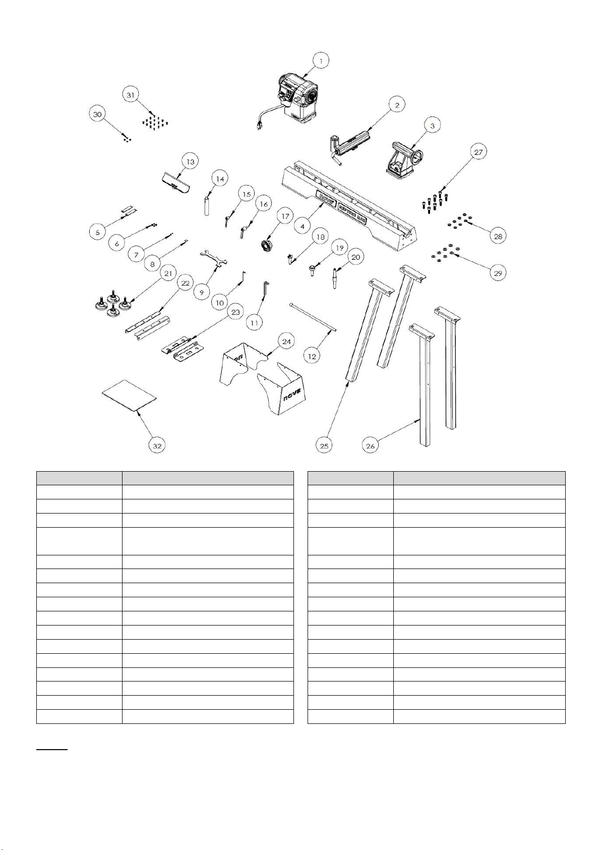
Neptune Max
ITEM NUMBERS
DESCRIPTION
ITEM NUMBERS
DESCRIPTION
1
Headstock Assembly (+HMI)
17
80mm Face Plate 1 ¼” 8tpi
2
Toolslide Assembly
18
2MT Spur Centre
3
Tailstock Assembly
19
2MT Live Centre
4
Main Bed 20
Double Ended Morse Taper –
Acruline Alignment Tool
5
Bed End Stopper Plate
21
Foot Assembly
6
Stopper Plate Screws M5 x 6mm
22
Stand Cross Plate
7
Set Screw M6 x 6mm
23
Stand Tool Tray
8
Soft Washer
24
Stand Cover
9
Universal Spanner
25
Stand Legs Set A
10
3mm Allen Key
26
Stand Legs Set B
11
10mm Allen Key
27
M12x35mm Cap Screw
12
Knock Out Bar
28
Spring Washer M12
13
Nova 9" Modular Tool Rest Bar
29
Flat Washer M12
14
Tool Rest Post 1" Shank
30
Flat Washer M6
15
Locking Handle – M8 x 20mm
31
M6x12mm Button Head Cap Screw
16
Locking Handle – M10 x 20mm
32
Neptune Manual
*Note: EU M33 model with ASR Euro lock but the ASR locking ring needs to be purchased separately.
Page 10

10
128-01-2310
128-0621-003
4.Setup and Assembling the Lathe
Workshop Environment
Your workshop should be set up appropriately for you to effectively use the lathe. The workshop should be setup
with the following factors taken into consideration:
1. Lathe Location
Locate the NOVA 15” lathe close to a power source in an area with good amount of lighting.
Leave enough clearance when the lathe headstock is swiveled around. Other machines in the
workshop should not interfere with the movement/operation of the lathe.
2. Lighting
The workshop should have adequate lighting. There should be enough lighting around the
lathe not to cast shadows upon the workpiece. A portable spotlight might be helpful.
3. Electrical
The NOVA 15” lathe requires an appropriate power outlet nearby to power the motor. The
outlet wiring must meet the local electrical safety standards. If in any doubt, seek advice
from an electrician. The length of an extension cable should be reduced as must as possible.
4. Ventilation
Workshop must have an adequate level of ventilation. The level of required ventilation
depends on the size of the workshop and the amount of work that is done within the
workshop. The use of dust collectors and filters will minimize your health risk.
Page 11
11
128-01-2310
128-0621-003
4.1 Unpacking and Preparing the Lathe
1. Remove all smaller items from the main carton. Do not discard carton or packing material until the lathe is
assembled and running satisfactorily.
2. Inspect contents for shipping damage; if any is found, report it to your distributor.
3. Compare the contents of shipping carton with the contents list in this manual. Report shortages, if any, to your
distributor. Note: Check lathe first – some parts may have been pre-installed.
4. Exposed metal areas of the Lathe, such as bed ways and spindles, have been factory coated with a protectant. This
should be removed with a soft cloth and a cleaner degreaser. Clean the bed areas under headstock, tailstock and
tool support base. Do not use an abrasive pad, and do not allow solvents to contact painted or plastic areas.
5. Ensure all protective films, specifically on the HMI panel, have been removed before use.
WARNING! Seek help when moving the NOVA 15” DVR lathe and its heavier components to help avoid risk
of injury. Use straps in good condition. Straps/lifting mechanisms must be properly rated for lathe weight.
Read and understand the contents of this manual and recommended procedures before attempting to
assemble or operate the Lathe or its parts.
DO NOT CONNECT POWER ON LATHE UNTIL FULLY ASSEMBLED.
4.2 Lathe Installation
Once the Neptune lathe has been unpacked, determine which mode of turning is best suited for the type of turning you are
planning to do.
Once a mode has been determined, please remove the end plates at each end of the bed, and slide the headstock, toolslide and
tailstock off the bed and place on a clean flat surface. This will allow you to configure the bed appropriately.
4.2.1 Determine Mode of Turning (Neptune Model)
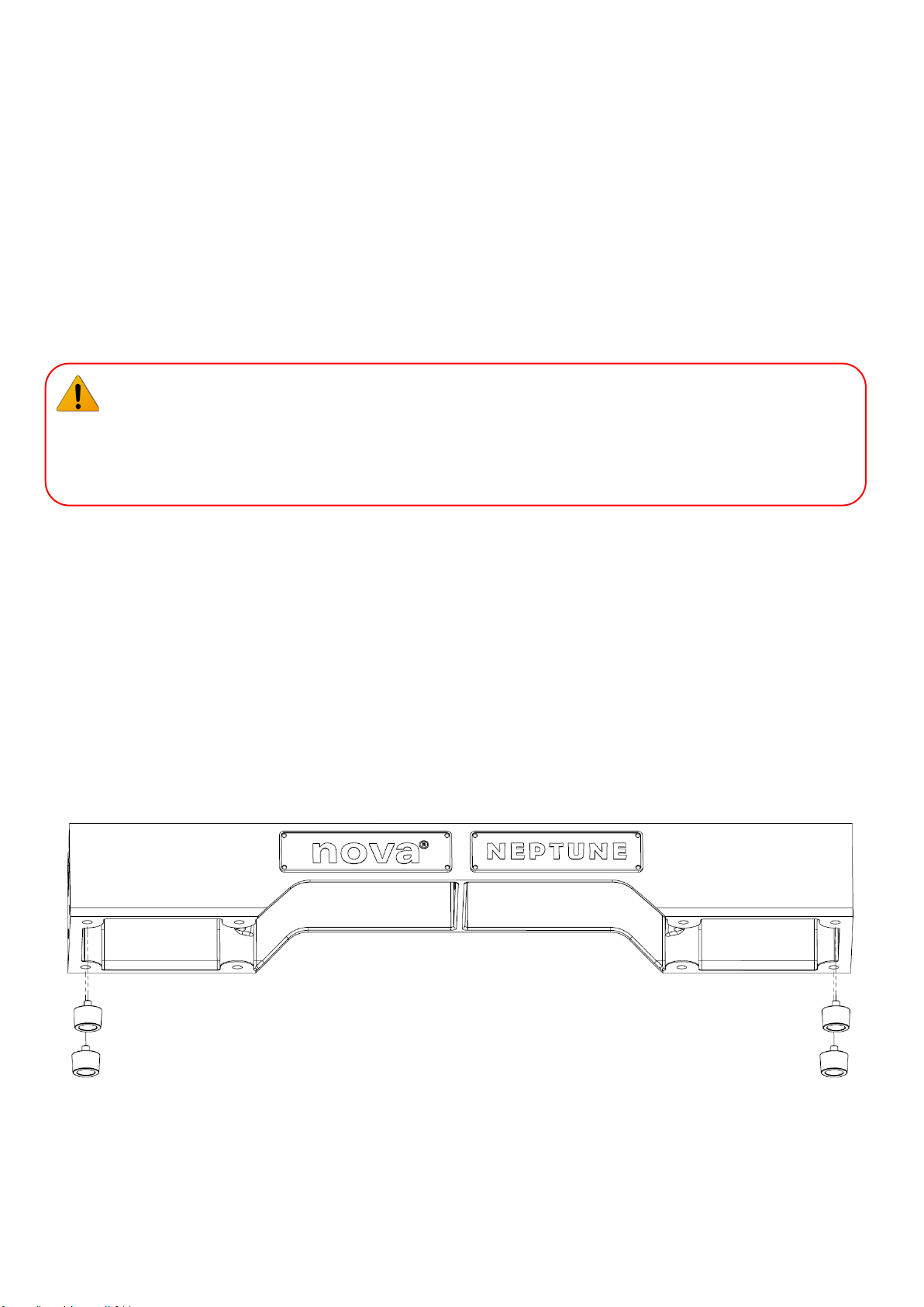
Mode 1: Free Standing on Rubber Feet
This mode is for in line spindle turning and small bowl work well balanced 6-8” 150-200 mm.
Do not use swivel head and for larger turning work with the rubber feet it is designed for easy portability. For larger work and
swivel head the machine must be bolted to the bench.
Assembly:
Flip the bed upside down onto a clean flat surface (ideally onto cardboard to protect the top surface of the bed). Screw the feet
into the bottom of the bed. Flip bed back onto its feet. Move onto Section 4.2.2.
Page 12
12
128-01-2310
128-0621-003
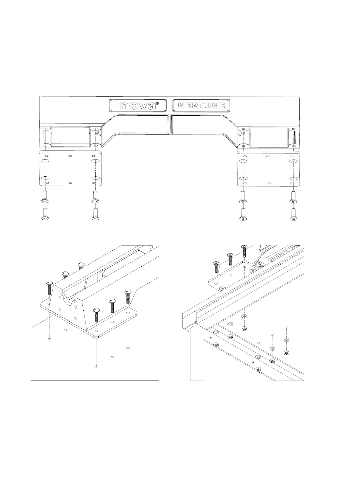
Mode 2: Free Standing on Bench with Optional Mounting plates SKU 5529168
This mode is for larger turning work and swivel of the head.
The type of turning and size of work pieces up to 12” with good balance and Headstock can be swiveled. It is recommended for
any turning work to secure plates to bench with screws or bolts. Through the holes provided in the plate.
Assembly:
Flip the bed upside down onto a clean flat surface (ideally onto cardboard to protect the top surface of the bed). Screw the
mount into to the bed using four countersunk M12 bolts. Flip bed onto the mounted surface. Screw the mount into the bench
using M10 coach bolts. Move onto Section 4.2.2.
Optional Accessory
Mounting Plate
Page 13
13
128-01-2310
128-0621-003
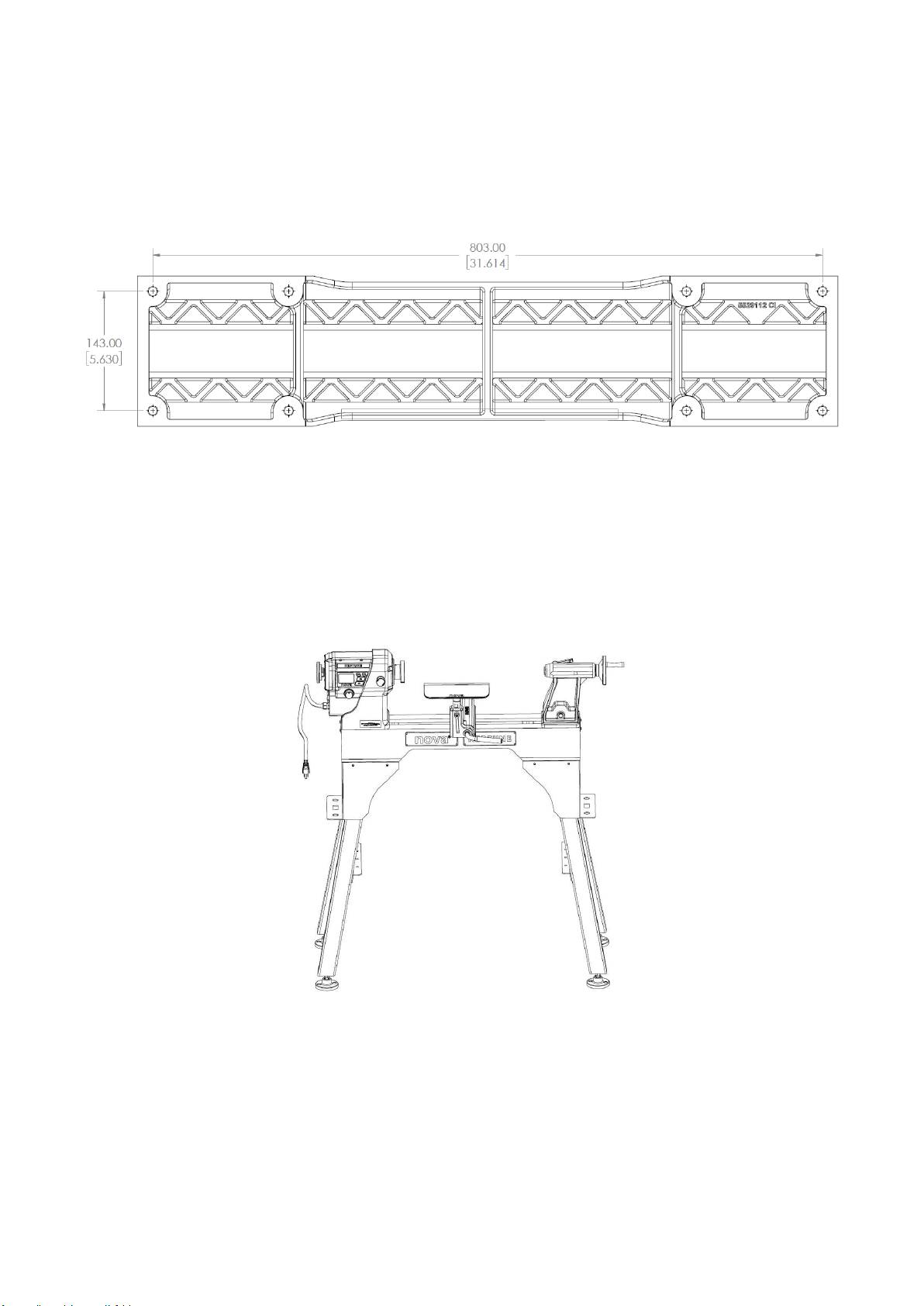
Mode 3: Bolt Directly to Bench
This mode is for all turning work and outboard turning.
The type of turning and size of work piece that is best suited for this mode is up to the limits of the turning in swivel head or
outboard turning mode. Take care to avoid unbalanced work pieces and balance accordingly. Turn at the slowest speed to avoid
out of balance forces and bring the speed up as the work piece is in balance.
Assembly:
If you wish to bolt the bed directly to your work bench, follow the bed profile shown below. Bolt the bed in place using four M12
bolts from below the bench. Move onto Section 4.2.2.
Mode 4: Floor Stand as a Floor Model Lathe
Turning and size of work piece is up to the limits of the turning envelope in swivel head or outboard turning mode. Take care to
avoid unbalanced work pieces and balance accordingly. Turn at the slowest speed to avoid out of balance forces and bring the
speed up as the work piece is in balance.
Assembly:
The bed is compatible with the Neptune Stand Accessory. The Neptune Stand accessory is sold as a separate assembly, please
refer to the assembly instructions that are included with the stand or to the instructions in the Neptune Max Stand setup section
of this manual (Section 4.2.2). Move onto Section 4.2.3.
Optional Accessory
Stand
Page 14
14
128-01-2310
128-0621-003
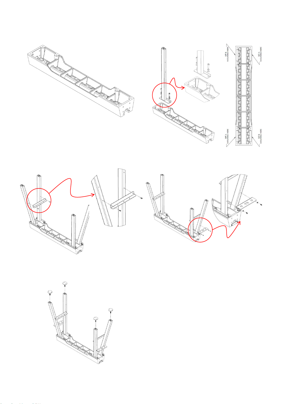
4.2.2 Assembly Bed to Stand (Neptune Max Model)
Step 1:
Lay the bed face down on a flat clean surface. It is recommended that
a piece of cardboard is placed between the bed and the floor to
protect the surface of the bed.
Step 2:
There are two sets of legs, Set A & Set B. Align each set as indicated
below with the mounting holes on the bed. Fasten in place.
DO NOT FULLY TIGHTEN AT THIS STAGE.
Step 3:
Align the cross plate with the holes on the inside of the legs. Fasten
in place.
DO NOT OVER TIGHTEN AT THIS STAGE.
Step 4:
Align the tool tray with the holes on the outside of the legs. Fasten
in place.
DO NOT OVER TIGHTEN AT THIS STAGE.
Step 5:
Fully tighten the M12 cap screws assembled in Step 2, followed by the M6 cap screws and the M6 button head cap screws assembled in
Step 3 and Step 4 respectively.
Step 6:
Attach the feet to the base of the legs.
Step 7:
Flip the stand over onto its feet so that it is right side up.
WARNING: Due to the weight of the stand, it is recommended that a
second person helps lift the stand.
Name Plate Side
Page 15
15
128-01-2310
128-0621-003
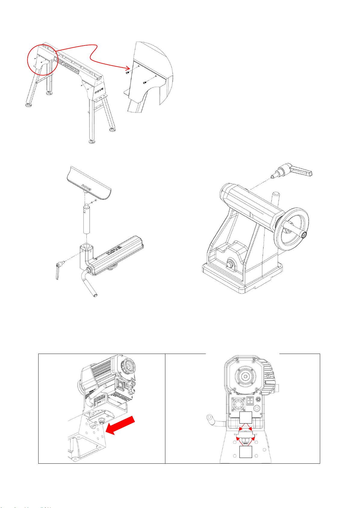
Step 8:
Align the cover plate with the holes on the side of the stand. Fasten
in place.
Step 9:
To balance the stand, adjust the feet accordingly by
screwing/unscrewing the feet from the base of the stand. Secure in
place by fastening the nut tightly against the base of the leg.
4.2.3 Assemble the Toolrest and Tailstock
Assemble the Toolrest
Assemble the Tailstock
4.2.4 Mounting the Headstock, Toolrest and Tailstock onto the Bed
1. Slide headstock, Toolrest, and tailstock onto bed, ensuring lock plate (A) is correctly lined up with bed way
(B), as shown below:
A
B
Page 16

16
128-01-2310
128-0621-003
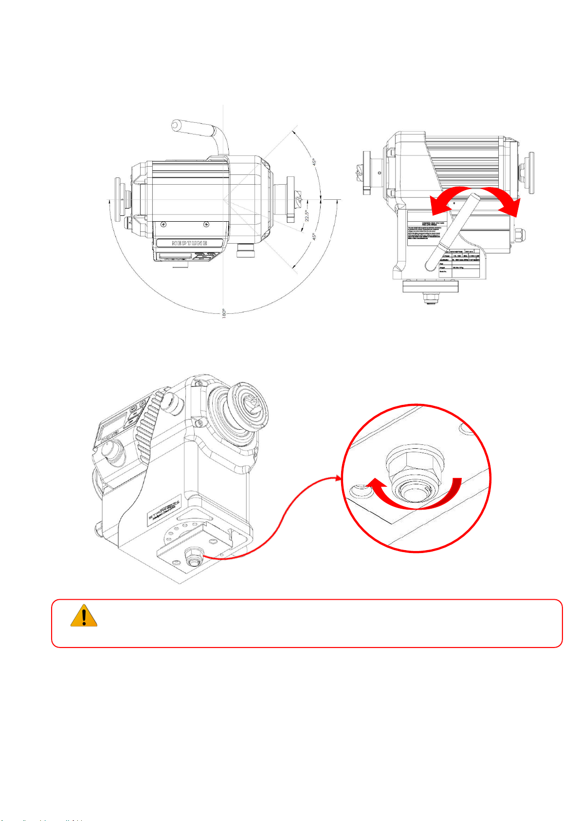
Note: Turn the lock handle to adjust the position of the lock plate if they cannot slide
onto the lathe bed section.
2. Replace stop plates on both ends of bed.
Screw end plate into bed to secure headstock onto bed
Screw end plate into bed to secure tailstock onto bed
B A B
A
Page 17
17
128-01-2310
128-0621-003
4.3 Positioning the Headstock on the Bed
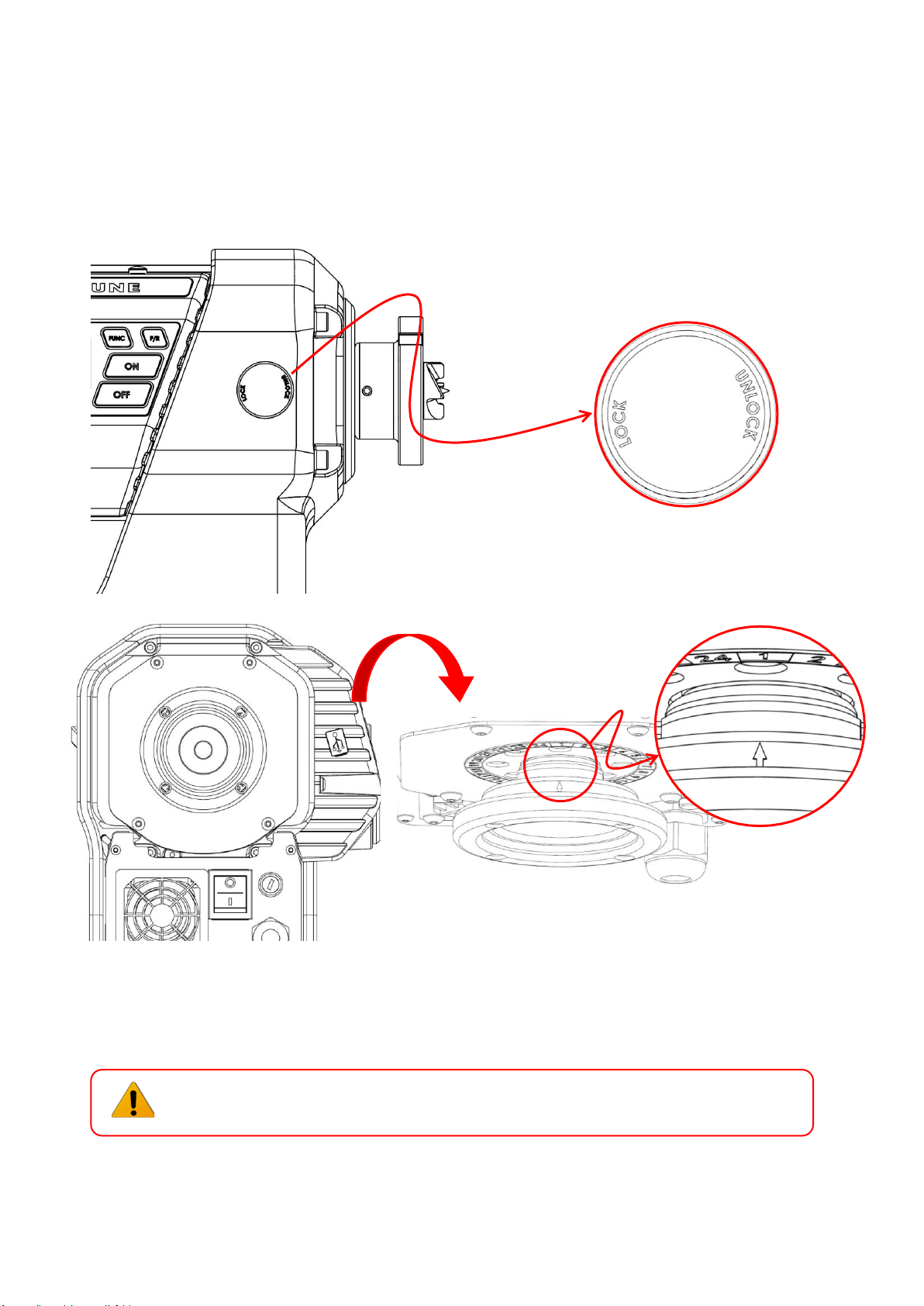
The headstock uses a cam lock assembly for securing in place along the bed. To move the headstock:
1. To unlock the headstock, push the locking handle backwards or lock the headstock by pushing the handle
forwards.
2. When the headstock is unlocked, slide and swivel the headstock along the bed to the desired position.
3. Re-Lock the headstock firmly, ensure the headstock is secured before running the lathe.
4. The locking force, orientation of the locking handle can be changed by adjusting the nut at the bottom of
the lock plate as illustrated.
WARNING! PINCH HAZARD – Remove hand from locking shaft when swivelling the
headstock.
Lock
Unlock
Unscrew to
adjust
Page 18
18
128-01-2310
128-0621-003
4.4 Spindle Index/Lock
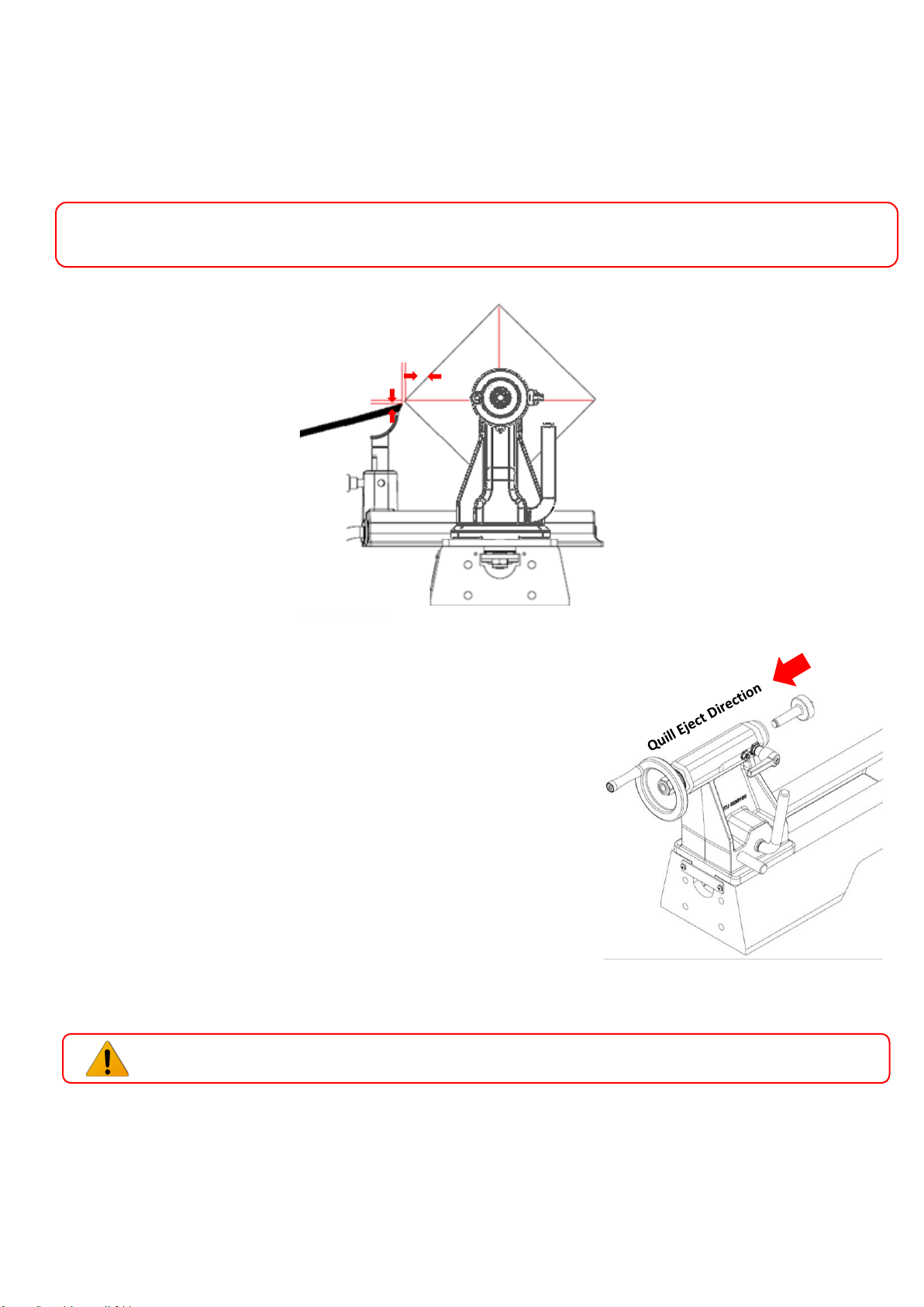
The spindle index pin locks the headstock spindle. It is selectable in 15-degree increments (24 divisions). An indicator
decal is on the rear headstock.
1. Stop the lathe.
2. To lock the spindle, lift up and turn the Locking Knob into the LOCK position until the internal pin engaged into
the index fly wheel. Caution: Ensure the pin engaged into a slot by turning the spindle with the hands. to
unlock, turn it into the UNLOCK position.
Spindle Lock
Arrow on rear handwheel indicates position of spindle indexing
WARNING! Make sure the index pin is disengaged before operating the lathe.
Page 19
19
128-01-2310
128-0621-003
4.5 Toolrest
Loosen the Toolslide clamp Handle counterclockwise, move the tool slide to the desired position, and tighten the
clamp handle clockwise.
Adjust the Toolrest close to the work piece. Exact positioning may be varied to suit the turner. Revolve the stock by
hand to make sure it clears the rest before starting the lathe. At intervals, stop the lathe and readjust the Toolrest.
WARNING! Lathe tools and chisels should remain on the Toolrest whenever the tool is in contact with
the work piece. Remove the Toolrest when sanding or polishing so fingers do not get pinched.
4.6 Tailstock
To move the Tailstock along the bed, release the Cam Lock Lever,
slide the Tailstock to the desired position and tighten the Lever to lock into
place as illustrated.
To move the Tailstock quill in or out, loosen the Quill Lock and turn
the Handwheel. Lock the quill in place with the Quill Lock.
The Tailstock Quill accepts centers and accessories with no. 2 Morse taper (#2
MT). To install a taper, insert the accessory firmly by hand. Do not pound the
taper into the hole.
To remove a taper, either wind the quill into the tailstock until the taper is
ejected or insert the operating bar through the Tailstock Quill hole. While
holding the taper so it does not fall, and then tap it out.
The Tailstock Quill is hollow, allowing you to bore holes through turnings if a hollow center is used.
WARNING! Never loosen the Tailstock Quill or Tailstock while the work piece is turning.
Starting Guidelines
Adjust Toolrest as Need
3mm (1/8in.)
Page 20
20
128-01-2310
128-0621-003
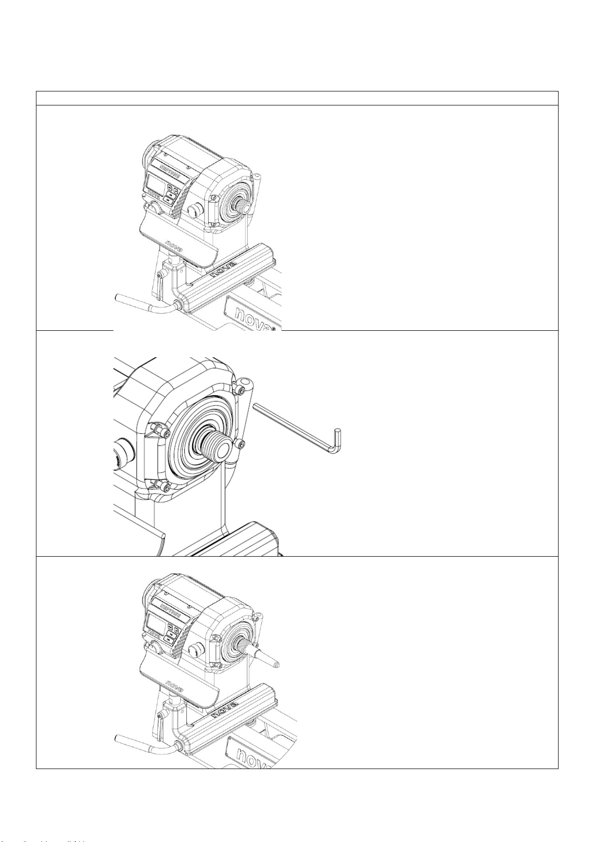
4.7 Lathe Alignment
Generally, new lathes are strictly inspected in factory and does not need to be aligned again. Over time, as the lathe
is used, you may need to re-align your lathe. To realign machine, please follow the method below.
1. Double Ended 2 Morse Taper method:
a. Lock the Headstock at 0° by using the locking handle on the bed. Slide toolrest up against the
headstock.
b. Loosen the motor mounting screws on the headstock, approximately 5-8 turns should be
acceptable.
c. Firmly install a double ended 2MT alignment tool into headstock spindle.
Page 21
21
128-01-2310
128-0621-003
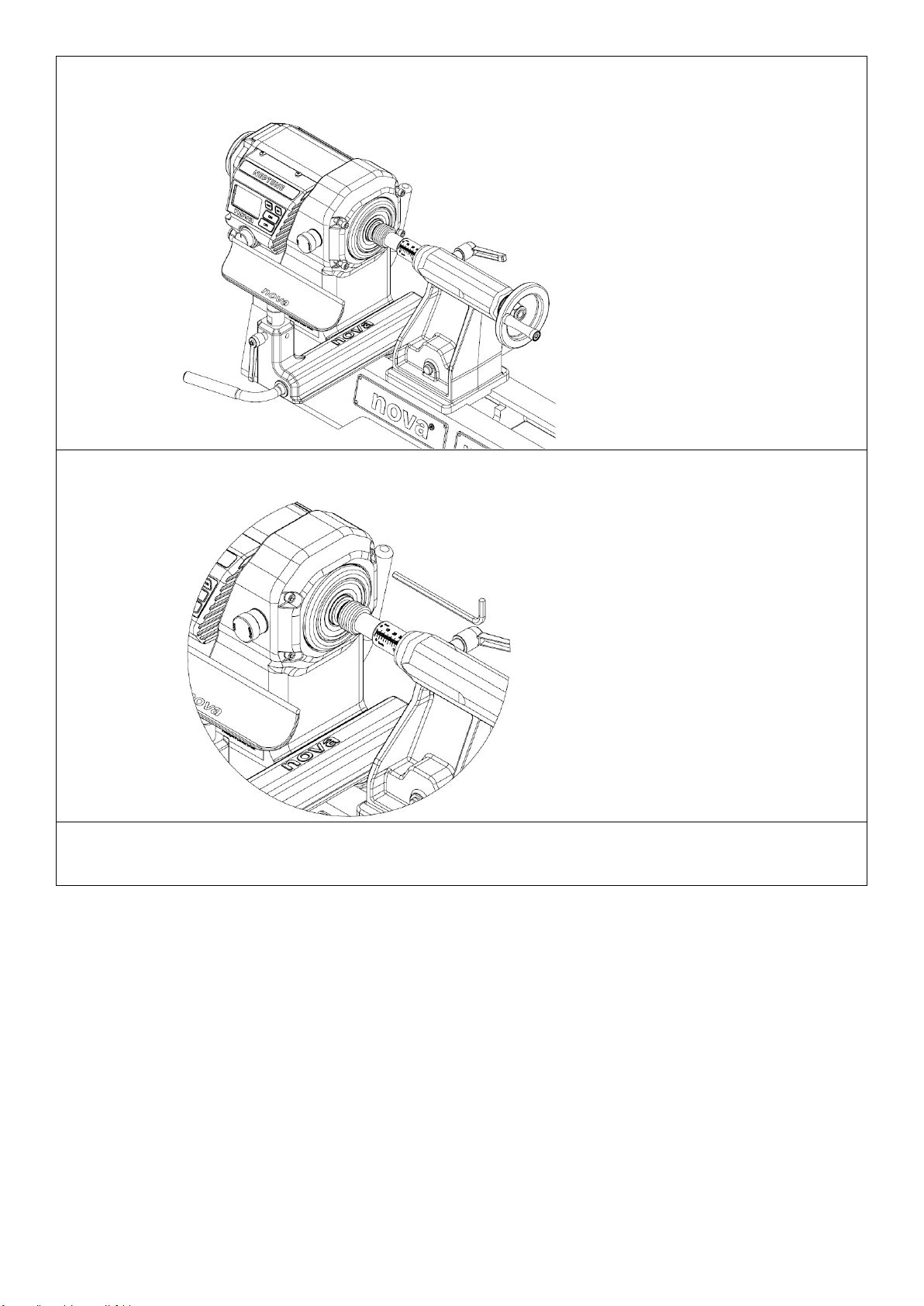
d. Slide tailstock to the headstock side of the bed, to firmly align the double ended morse taper with
the motor spindle. Lock the tailstock into place. Wind the tailstock handwheel until the motor
flange sits securely against the inner ring of the headstock.
e. Tighten the motor mounting screws against the headstock, tightening the screws in a diagonally
opposite sequence.
f. Remove the double ended morse taper from the headstock and tailstock (use a knockout bar if
required).
Page 22
22
128-01-2310
128-0621-003
4.8 Mounting a Faceplate or a Chuck
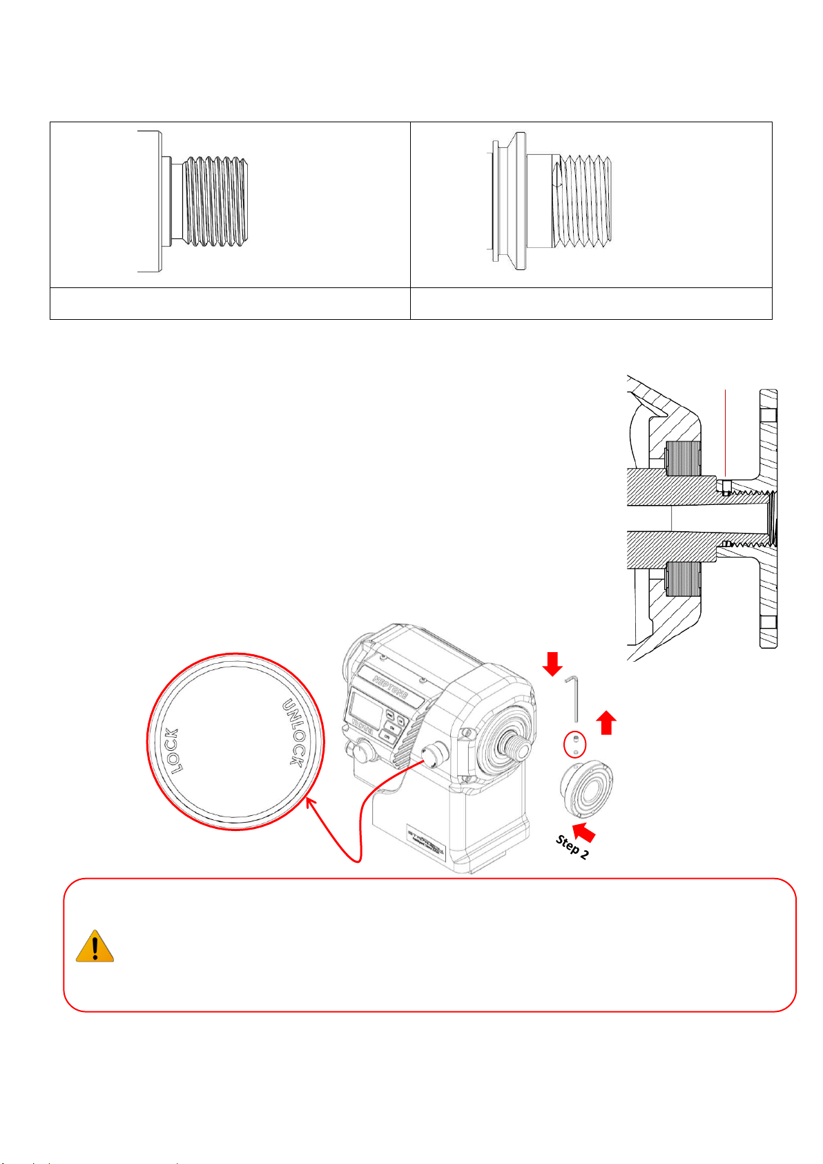
The thread size of headstock Spindle is 1.25" RH (Standard Version), or M33 RH (Euro Version), depending on your
model.
4.8.1 Mounting on the Standard Version Spindle
Use the Spindle Index Pin to lock the headstock spindle before commencing.
Step 1:
Use the Allen key to remove the safety screw and soft washer from the faceplate
or chuck before installation.
Step 2:
Thread the faceplate or chuck onto the spindle thread all the way. Ensure the
surface of the faceplate is sitting flat against the spindle surface.
Step 3:
Tighten the safety screw and soft washer on the faceplate or chuck to lock
the faceplate in place.
Unlock the spindle before turning the machine on.
WARNING! The faceplate or chuck body must contact the shoulder on the spindle bearing.
When installing or removing the Faceplate or Chuck from the spindle, the side-locking grub
screws MUST be completely removed. This avoids any potential damage to the spindle that the
safety screws may cause if it were not completely removed, when winding the Faceplate or Chuck
on or off the spindle.
1 ¼”
M33
Standard Version Spindle
Euro Version Spindle
Step 1
Step 3
Make sure there is no
gap between faceplate
and spindle
Spindle Lock
Page 23
23
128-01-2310
128-0621-003
4.8.2 Mounting on the European Version Spindle
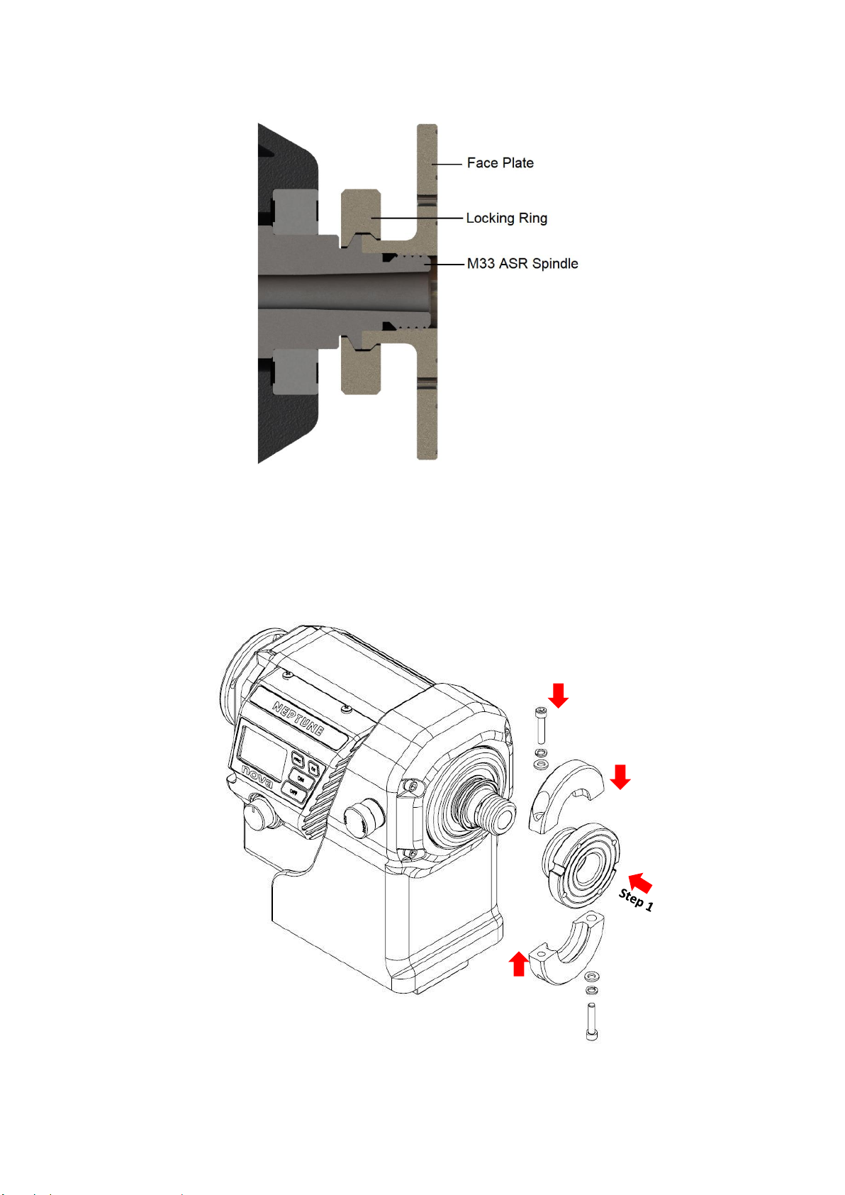
The diagram below illustrates a cross sectional view of an M33 ASR Eurolock version spindle with an M33 ASR
Eurolock chuck mounted.
Locking Ring Installation Procedure
Use the Spindle Index Pin to lock the headstock spindle before commencing.
Step 2
Step 3
Step 4
Page 24
24
128-01-2310
128-0621-003
Step 1:
Thread the M33 ASR faceplate or chuck onto the spindle thread all the way in. Check that the spindle and the
faceplate/chuck are touching at the clamping ridge.
Step 2:
Put the lower part of the locking ring under the clamped rings.
Step 3:
Put the upper part of the locking ring above the clamped rings.
Step 4:
Use an Allen key to tighten up two bolts on the locking ring.
Unlock the spindle Index Pin before turning the machine on.
IMPORTANT NOTE: The Index Pin is designed for indexing purposes only, not for leveraging
against when removing faceplates, inserts and chucks. For this we recommend holding the spindle
using a spanner to clamp the lathe hand brake mounting surface.
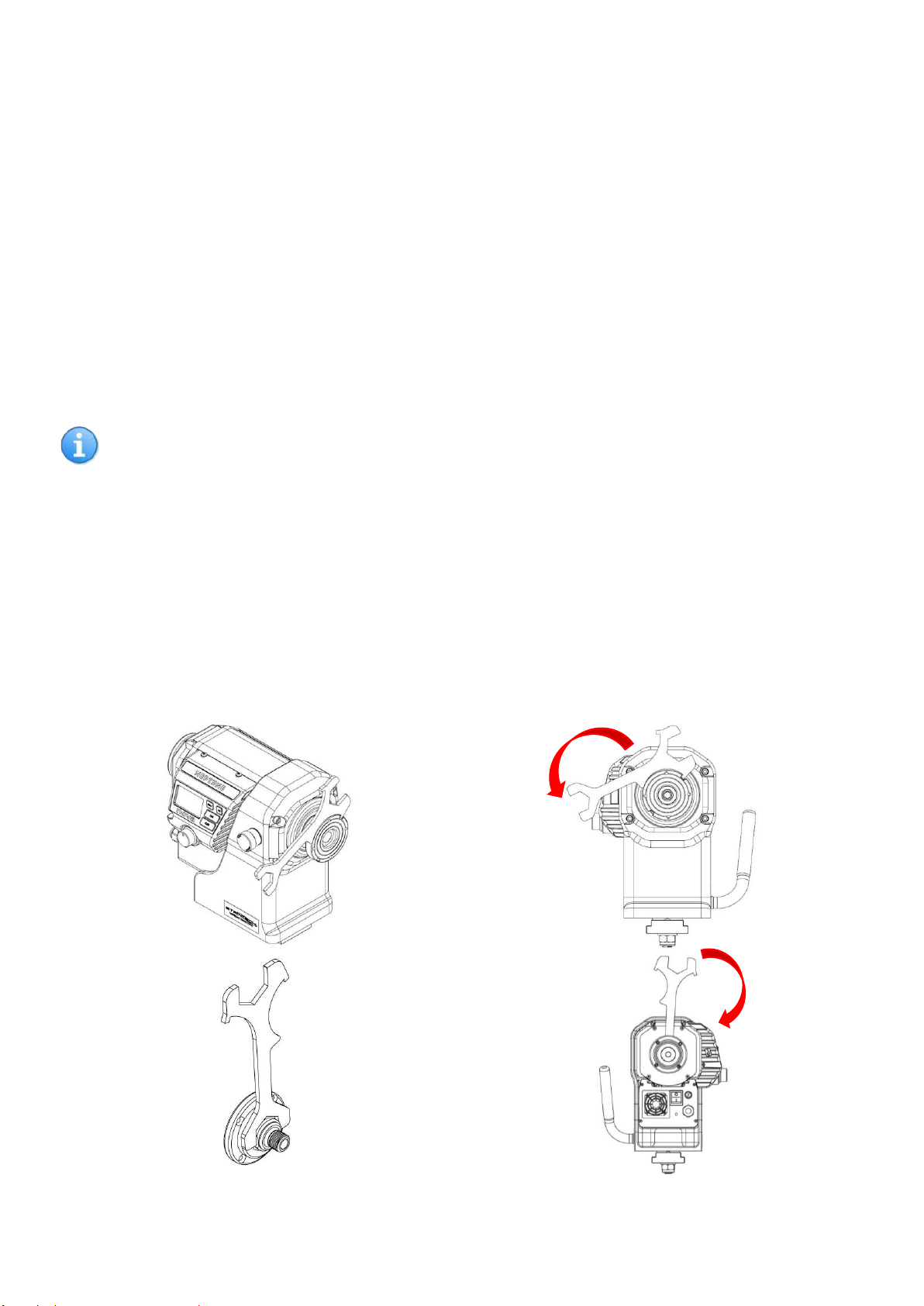
4.9 Removal of Faceplate and Handwheel
Once used, the faceplate may have been overtightened onto the spindle. In this case, the spanner is required to remove the
faceplate. Please ensure that the set screw/ASR ring has been removed before attempting to unscrew the faceplate.
Align the spanner as shown with the slots on the faceplate. Once aligned apply pressure in the direction shown to loosen the
faceplate.
Similarly, with the handwheel on the rear of the motor, to remove, the spanner will also be required. Align the spanner with the
flats of the handwheel and apply pressure in the direction shown.
Page 25
25
128-01-2310
128-0621-003
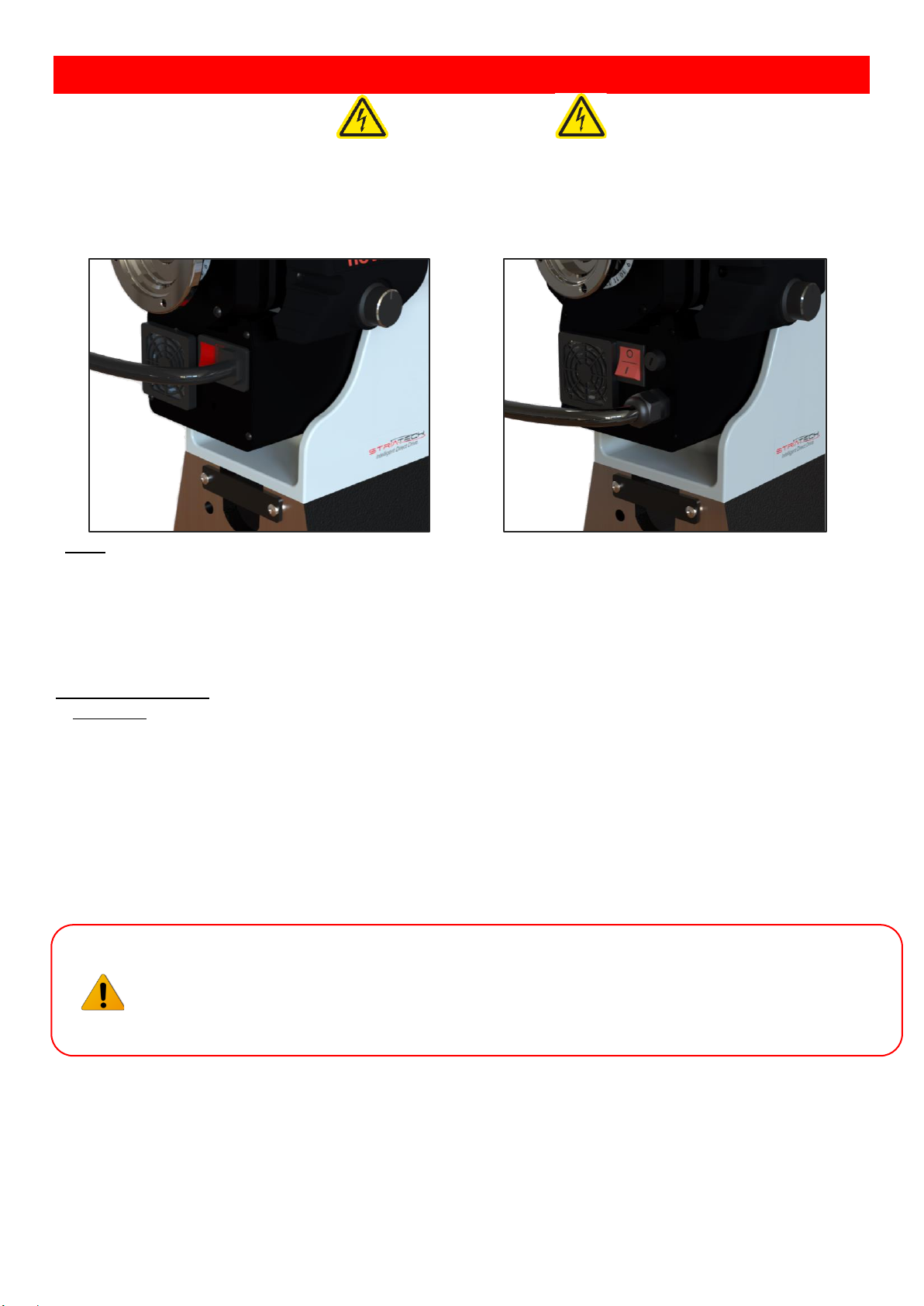
5. Connecting to Power
Warning!
Improper power connection may result in a risk of electrical hazard.
Before plugging the NOVA lathe into the power source, check that the:
1. The main power switch is turned off.
2. Power source is switched off.
Note: This image on the left-hand side is the European version of the NOVA wood lathe. Other versions will have a
hard-wired power cable (shown on the image on the right-hand side).
The power cord that is installed on the NOVA lathe will have a three-prong plug which includes a ground prong. The
plug must be connected to a matching outlet that his properly installed and grounded in accordance with local
electrical codes.
For 110V Outlet Only:
A temporary adapter can be used to plug into a two-pole outlet if a three-prong outlet is unavailable in your
environment. The ground tab on the adapter must be connected to the screw on the outlet for proper grounding. This
adaptor should only be used until a qualified electrician can install a properly grounded outlet.
➢ Note: If an extension cable is required, make sure to check the following:
1. Extension cable gauge is appropriate for the length and voltage.
2. Is the cable properly insulated?
If in any doubt, please contact your local electrician to inspect the cord according to the local electrical standards
before use.
IMPORTANT:
• A surge protection device is recommended when using the lathe.
• A surge protection device must be rated to at least 15A should be used in countries where 110V are
used as a standard. In countries where 240V is used, a surge protector must be rated to 10A.
Page 26
26
128-01-2310
128-0621-003
5.1 Ground Fault Interrupters (GFI)
For a GFI to be compatible with the DVR motor, it is recommended have a leak current threshold rating of 30mA
(0.03A)
Note: Normal household GFI will typically be rated at 5mA (0.005A) which may
trigger during the operation of the DVR motor. However, frequent tripping of the
GFI will not cause any harm to the DVR motor or its control electronics as it has a
built-in protective circuit to prevent damage from frequent switching.
5.2 Input Voltage Selection
The NOVA lathe is capable of handling both 110V and 220V without any changes to its internal circuits.
The lathe will automatically recognize the input voltage to the lathe and adjust the output power. Simply change the
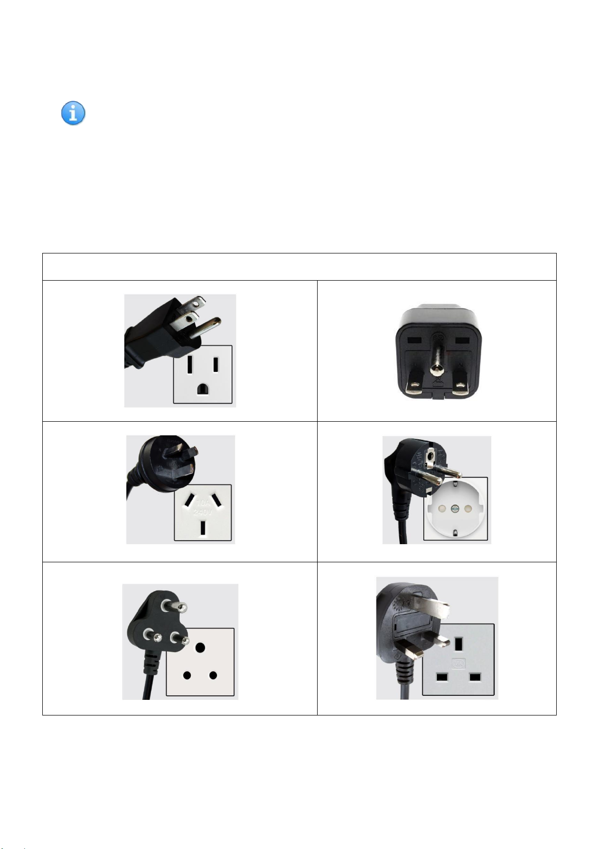
input power plug to a suitable plug for the desired input voltage to change the lathe’s input voltage.
Electrical outlet plugs Country Standard
USA, Canada & Japan 110V 15A
USA 220V (NEMA 6-15P)
Australia/New Zealand & China 220V 10A
Europe except UK and Ireland 220V 10A
South Africa 220V 10A
UK and Ireland 220V 10A
Page 27
27
128-01-2310
128-0621-003
6. Lathe Operation on HMI Panel - Human Machine Interface
Panel
6.1 HMI introduction
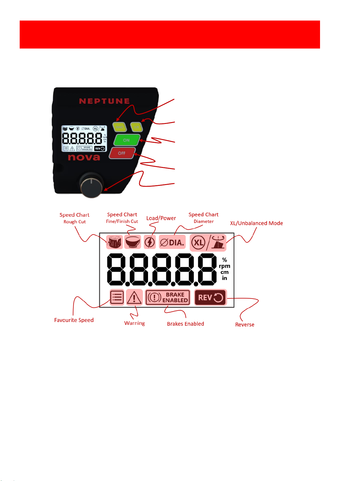
The Neptune HMI panel consists of four keys, one speed knob for the lathe operation, the 2.4” LCD shows the status
of the lathe in real time, these keys and icons on the panel are illustrated as follows.
[FUNC]: Access or Exit to the lathe functions.
[F/R]: Toggle Motor Forward /Reverse direction.
[ON]: Start the lathe or “ENTER” action in FUNC.
[OFF]: Stop the lathe or “CANCEL” action in FUNC.
[Speed Knob]: Speed adjustment and “CONFIRM”
action in FUNC operation.
• Favourite Speed- 4 favourite speeds, pre-set and reprogrammable in FUNC.
• Warning- Warnings indicator
• BRAKE ENABLED – Enabled the brake with OFF function.
• REV- Reversed direction selected.
• Speed Chart - Rough or Fine/Finish cut, pre-set and reprogrammable in FUNC.
• Load/Power- “Running” indicator and actual load in FUNC.
• ΦDIA- the Diameter unit indicator of Speed Chart in FUNC.
• XL/Unbalanced - XL/Unbalanced mode in FUNC.
Page 28

28
128-01-2310
128-0621-003
6.2 General HMI Operations
6.2.1 Start-Up
Turn on the switch, the HMI will run the self-test in 3 seconds. During the test, the LCD will show all icons and software
version No. before it goes to the Home page. At the home page, the machine is ready to run now, the default speed is
500 RPM.
Software Version No.
Home Page
6.2.2 Run the Lathe
Press [ON] when the LCD is on the Home page, the motor will accelerate to reach the set speed.
6.2.3 Stop the Lathe
Press [OFF] at any time, the motor will be stopped with/without brake, the LCD will display the Home page. Please
refer to FUNC section regarding the brake option.
6.2.4 Forward/Reverse
Press [F/R] when the LCD is on the Home page - the REV icon will be toggled between forward and reverse*.
*For your safety, the FWD/REV selection is active only when the lathe stops spinning.
Speed Screen with Reverse Mode Engaged
6.2.5 Speed knob
The speed knob has two functions: Speed control, Select & Confirm in FUNC.
• Fine speed Control — +/-5 RPM by Turning it in clockwise or counter-clockwise while the LCD is on the Home
Page or the Motor Running.
• Coarse speed Control — +/-50 RPM by PUSH DOWN+ Turning it in clockwise or counter-clockwise while the
LCD is on the Home Page or the Motor Running.
• Select & Confirm in FUNC— general operation, “Turn it to select, PUSH DOWN to Confirm or Save”, More
detail refers to FUNC section below.
6.3 FUNC- Advanced Functions and features
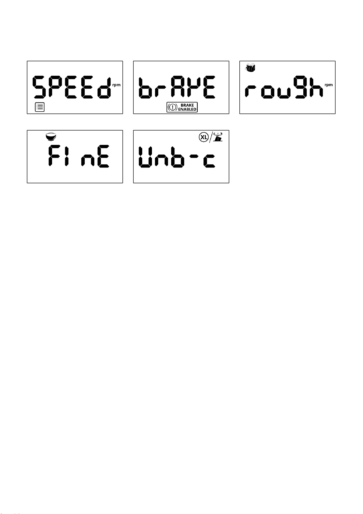
The FUNC menu provides 5 pre-set, programmable functions for multiple turning applications:
• Favourite speed
• Brake Enabled
• Speed chart for Rough cut
• Speed chart for Fine/Finish cut
• XL/Unbalanced Mode
Page 29
29
128-01-2310
128-0621-003
6.3.1 General operation to Enter and Exit FUNC Menu
When the LCD is on the Home page, Press [FUNC] once to enter the function page, turn the speed knob clockwise or
counter clock wise, the LCD will show all 5 functions in a sequence:
Favourite speed->Brake Enabled->Rough cut->Fine cut-> XL/Unbalanced
When the LCD is on the function page, Press [FUNC] once again or Press [OFF] to exit back to the Home page*.
* Press [FUNC] on the function pages, it acts as “BACK” to previous page, Press [OFF] means exit to Home page
directly.
6.3.2 General operation to Enter desired functions
Turn the speed knob to desired function, press [On] to confirm the selection. The LCD will show desired function page.
See Favourite Speed example below.
When the LCD is on desired function page, Press [FUNC] once again to back to previous Function page or Press [OFF]to
exit to the Home page.
6.3.3 Favourite speed
The HMI is built in four favourite speeds for a quick start-up. To use, change and save the settings, follow the
instructions as follows. While the motor is running or stop:
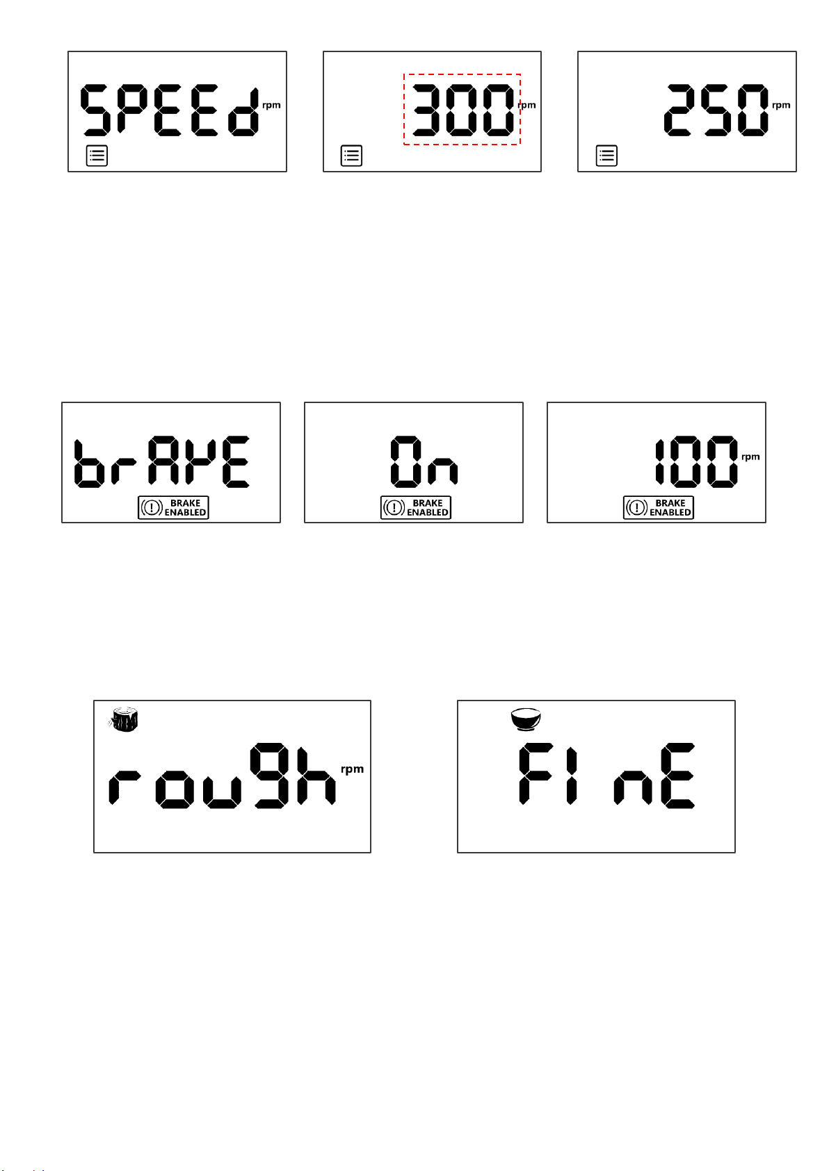
Step1 :Press [FUNC] once on the Home page, and then press [ON] again to enter the Favourite Speed page, turn the
speed knob to select the four default speeds in sequence: 250RPM,500RPM,750RPM,1000RPM, press [ON] to run
the lathe or press [FUNC] or [OFF] to exit.
Step2: If [ON] pressed, the LCD will show or run default RPM immediately on the home page.
*Simplified instructions to change &save the default speed as:
[FUNC]-> [ON]->[Speed knob to Select speed #]->[Press Down& Hold to edit]->[Speed knob to Change speed]>[Press Down& Hold to confirm], which describes as follows:
press [FUNC] once on the Home page, then press [ON] to enter the Favourite Speed page, turn the speed knob to
select one of default speeds, press [Down & Hold] the speed knob until the Favourite Page becomes flashing, turn
the speed knob to adjust the speed as desired and then press [Down & Hold] the speed knob until the Favourite
Page stops flashing. The new speed is saved into speed slot, Press [ON] again, the LCD will show or run new speed
immediately on the home page.
Favourite Speed Function Page
Brake Enable Function Page
Rough Cut Function Page
Fine Cut Function Page
XL/Unbalanced Function Page
Page 30
30
128-01-2310
128-0621-003
Favourite Speed Function Page
(Flashing)
Programming Mode
Default Pre-set Speed
6.3.4 Brake Enabled
The brake is optional feature to combined with OFF operation, with the brake ON, the motor speed will be
deaccelerated quicker than normal (the default setting is OFF).
Step1: Press [FUNC] once on the Home page, turn the speed knob to Brake Enabled icon, press [ON] to enter the
Brake Enabled page or press [FUNC] or [OFF] to exit.
Step2: On the Brake Enabled page, turn the speed to change OFF to ON, press [ON] to confirm, the LCD will show
Brake Enabled Icon on the Home page.
Brake Enabled Function Page
Brake Enabled ON
Speed Screen with Brake Enabled
6.3.5 Speed chart for Rough /Fine cut
The speed chart is a recommend, editable speed guide/reference according to the diameters of the wood and type
of turning. It’s accessible whenever the motor is running or stop:
Step1: Press [FUNC] once on the Home page, turn the speed knob to Rough cut or Fine cut icon, and then press [ON]
to enter the Rough cut/Fine cut page or press [FUNC] or [OFF] to exit.
Rough Cut Function Page
Fine Cut Function Page
Page 31
31
128-01-2310
128-0621-003
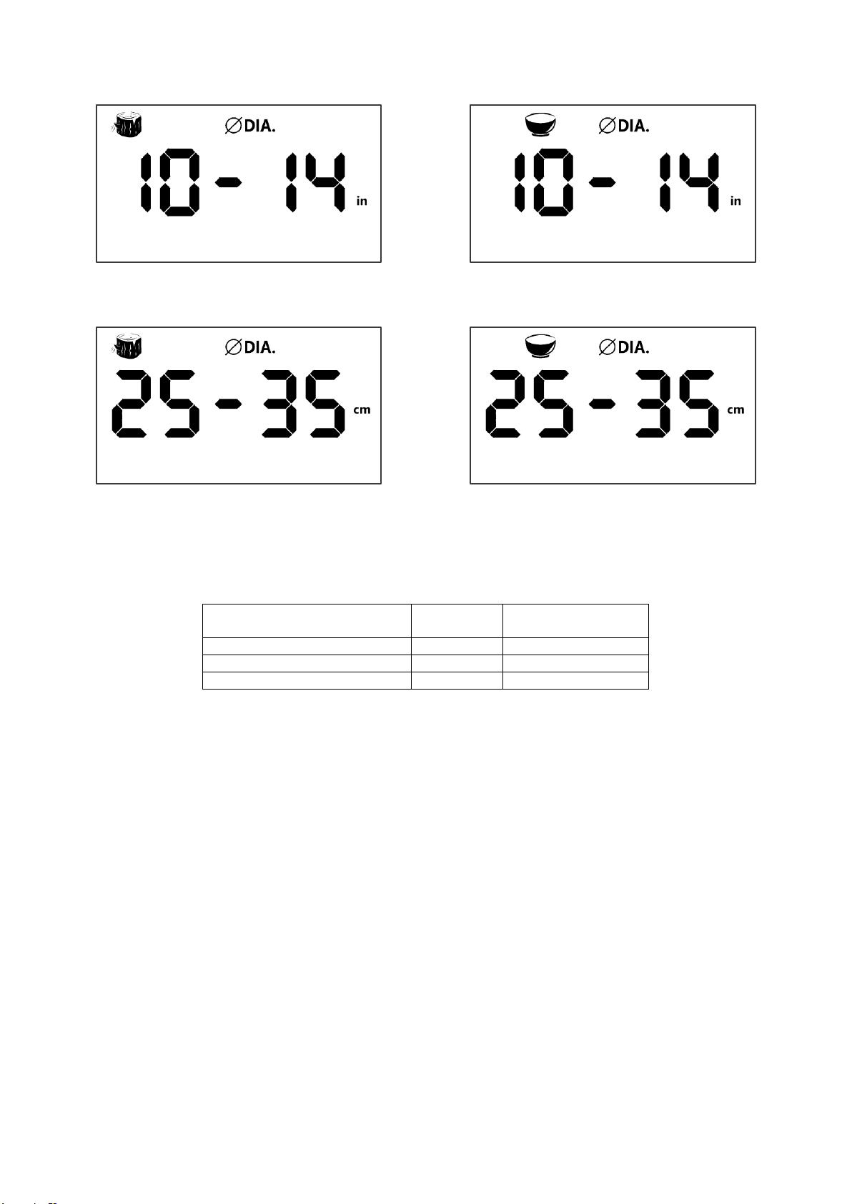
Step2: At the Rough cut/Fine cut page, turn the speed knob to Diameter options#1-3, small, medium and large size.
press [ON] to confirm or press [FUNC] or [OFF] to exit.
Rough Cut (Imperial) - Diameter Selection Page
Fine Cut (Imperial) - Diameter Selection Page
* Press [Down & Hold] the speed knob for 2S to change Imperial or Metric,
Rough Cut (Metric) - Diameter Selection Page
Fine Cut (Metric) - Diameter Selection Page
Step3: Once the wood size confirmed, the LCD will show recommend RPM immediately on the LCD screen *.
*The default speed chart for Rough Cut and Fine Cut as the table below.
Diameter of the Woods
Rough Cut
Fine/Finished Cut
01-06”/ 0 - 15cm
750 RPM
1450 RPM
06-10”/ 15 - 25cm
450 RPM
1000 RPM
10-14”/ 25 - 35cm
250 RPM
350 RPM
To change default speed, press [Down & Hold] the speed knob until the Rough or Fine Page becomes flashing, turn
the speed knob to adjust the speed as desired and then press [Down & Hold] the speed knob until the Rough or Fine
Page stops flashing. The new speed is saved now.
Press [ON] again, the LCD will show or run new speed immediately on the home page.
6.3.6 XL/Unbalanced Mode
The HMI offers smart speed profiles for XL/Unbalanced turning operation, such as slow starting up, steady and
smooth speed acceleration for unbalance wood piece, the mode is ONLY accessible when the motor is stopped, the
default setting is OFF.
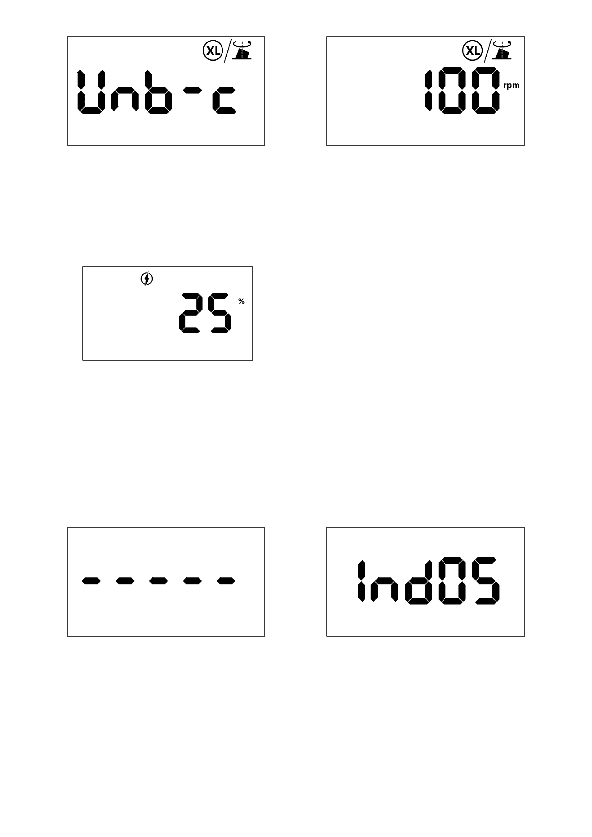
Step1: Press [FUNC] once on the Home page, turn the speed knob to XL/Unbalanced icon, and then press [ON] to
enter the XL/Unbalanced page as below or press [FUNC] or [OFF] to exit.
Step2: Turn the speed knob to change OFF to ON, press [ON] to confirm, the LCD will show XL/Unbalanced Icon on
the Home page. When the mode is on, it will apply the speed profiles immediately for the turning.
Page 32
32
128-01-2310
128-0621-003
XL/Unbalanced Function Page
Speed Screen with XL/Unbalanced Mode Engaged
6.4 Miscellaneous
6.4.1 Load monitoring Real time
The HMI can show a load factor as reference for turning operation.
While the motor is running, press [Down & Hold] the speed knob for 2S, the LCD will show the approximate capacity
of the motor being used by turning operation, press [Down & Hold] the speed knob for 2S again, the LCD will come
back the Home page.
Load Factor Page
6.4.2 Electronic Indexing
The HMI provides 24 electronic indexing positions.
*STOP the motor, Unlock the spindle lock first, make the spindle free before the operation!
On the Home page, press [FUNC]+[ON] for 2 seconds, the motor will be initialized and self-aligned with the motor
low noise for 3 seconds, the LCD will show the dash line and then show Indexing No.1 .
Turn the spindle clockwise or counterclockwise slowly, the 24 indexing numbers will be shown on the screen in
sequence. When the number changed to the desired position, turn the spindle lock to "Lock” position.
Initialization
Indexing
Press [FUNC] or [OFF] to exit the function.
Page 33

33
128-01-2310
128-0621-003
6.4.3 HMI Safety Lock
User can lock the HMI panel to prevent unpredictable operation from others. e.g Children or accident etc.
When the motor stops and on the Home page, press [Down & Hold] the speed knob for 2 seconds. The HMI will be
locked, HMI operations is disabled. press [Down & Hold] the speed knob for 2 seconds again. The HMI will be
unlocked, HMI operations is enabled, see the LCD information below.
Screen is locked
6.4.4 Warning messages
The warning message table is not editable information, *Try to report the fault with Error code.
Error code
Error description
Error code
Error description
E-0
Unexpected Fault
E-6
Low Voltage
E-1
SRM not Rotate
E-7
PFC_Fault
E-2
RPS_State_Error_0
E-8
Overheat
E-3
RPS_State_Error_1
E-9
EEPROM_Data_Fault
E-4
Hardware Fault
E-10
EEPROM_Work_Fault
E-5
Unexpected Trap
6.4.5 Factory Reset
Stop the motor first, press [Down & Hold] speed knob +[ON] for 3second. The HMI is reset to the factory settings,
the machine will reboot again.
6.4.6 USB mode for HMI firmware upgrade
Stop the motor first, press [Down & Hold] speed knob +[FUNC] for 3second. The HMI enters the USB mode for
firmware upgrade.
Download HMI USB/DFU update software and firmware from the website: www. teknatool.com, follow the
instructions to upgrade HMI firmware.
Page 34

34
128-01-2310
128-0621-003
7. Maintenance
• WARNING
Improper power connection may result in a risk of electrical hazard
Regular maintenance is essential when considering the long-term use of the lathe.
Maintenance After Each Use
1. Clean the work area and lathe.
2. Vacuum shavings and dust from the headstock, table and base.
Monthly Maintenance
1. Wax coat the exposed cast iron parts with a good quality paste wax. Buff off thoroughly.
2. Check tightness of nuts and bolts.
3. Clean all tapers to ensure a secure fit.
6-months Maintenance
1. Lubricate the tailstock quill and its inside threads with a light coat of light weight oil.
2. Check for any rust on the underneath the toolrest, tailstock and on the lathe bed. If there is rust on the
surface, remove it by using a rust removal agent with an abrasive sponge.
➢ Note: Some rust removal agents may leave a stain on the metal surface. Please check on an area where
stains are not easily visible before applying onto the actual metal surface.
Cleaning the Toolslide
If the toolslide becomes hard to move and adjust, cleaning and lubrication are required.
1. To allow the toolslide move more freely along the bed, make sure the bed rails are clean. Apply some paste
wax to the rails.
2. If the tool slide is difficult to adjust, remove the tool slide from the lathe bed. Clean the tool slide camshaft
(round eccentric rod) with a petroleum-based solvent. Lubricate the rod with lightweight oil or a silicone
spray.
3. Slide the base back onto the lathe bed.
Cleaning the Tailstock
If the tailstock quill becomes hard to adjust or the Handwheel is hard to turn, cleaning and lubrication are required.
1. Remove the M16 nylon lock nut from rear of the tailstock handwheel. Once removed, the handwheel and
the key that holds it in position, may be removed.
2. Remove the quill by unscrewing the tailstock quill lock handle off from the tailstock body and extending the
quill out all the way. Remove handwheel from the tailstock body.
3. Wipe clean all parts including the inside of the tailstock slot.
4. Lubricate the quill, quill lead screw and tailstock slot with lightweight oil, apply small amount of oil to the
quill threads.
5. Reassemble the tailstock.
Page 35

35
128-01-2310
128-0621-003
8. Troubleshooting
8.1 Mechanical Issues
SYMPTOM
PLACE TO CHECK
HOW TO RESOLVE
Excessive Vibration
▪ Work attached to the lathe
▪ Lathe Mounting
▪ (Either on bench or stand)
1. Remove any work pieces/tools attached to the
headstock, inspect if there is any foreign materials or
damages to the threads.
2. Attach the tools one at a time to check which part is
causing the vibration.
3. Extra weights can be added to reduce the amount of
vibration that occurs from large, unbalanced work
pieces.
Faceplate or chuck running
out of true
▪ Back of face plate
▪ Threads
▪ Inner threads on faceplate
▪ Spindle thread on
headstock
1. Inspect if there is any damage on the threads.
2. Mount the faceplate or chuck onto the machine and
check if it is seating securely on the bearing.
Turning tools not sliding
smoothly across Tool rest
Tool rest surface
Lightly use sandpaper or a grinder to smooth out the
top surface of the tool rest.
Spur drive centre/live
centre not holding in
spindle or quill taper when
turning
Morse Taper surface
1. Inspect both male and female Morse Taper surfaces
to check for any foreign materials or defects on the
surface.
2. Clean the surface and remount the tools.
Tailstock and Headstock
centres not aligning
▪ Lathe bed connection
▪ Headstock detent position
▪ Tailstock adjustment plate
1. Inspect all connections of the bed sections to make
sure all the top surfaces are flush with one another.
2. Check to ensure the headstock is properly locked in
the zero-degree detent position.
3. Loosen the tailstock adjustment plate located on the
bottom of the tailstock and align the headstock and
tailstock. Tighten the tailstock adjustment plate to
finish.
Tailstock Handwheel
hard to turn or will not turn
▪ Quill lock
▪ Inside the tailstock quill
housing
1. Check if quill lock on the tailstock is not engaged.
2. Fully extend the tailstock quill out to extract the quill
from its housing. Inspect both quill and housing
surface and threads for any defects and foreign
materials. Apply lubricant to quill surface and thread
and reassemble.
Tailstock binds
while sliding along the bed
▪ Lathe bed
▪ Tailstock adjustment plate
1. Check for defects or foreign materials on the bed.
2. Loosen the tailstock lock.
Tailstock jumps
at bed section joints.
▪ Lathe bed
▪ Tailstock bottom surface
1. Inspect uneven surfaces on the lathe bed and make
sure the bed connection areas are flush.
2. Check for any defects and foreign materials on the
bottom of the tailstock casting.
3. Use sandpaper to lightly sand down the defects on
the lathe bed or the tailstock casting.
Page 36

36
128-01-2310
128-0621-003
9. Teknatool Warranty
NOVA Limited Warranty
4499 126
th
St North | Clearwater Florida 33762
teknatool.com | 727.954.3433
Our policy is one of continuous improvement. We therefore reserve the right to change specification/design without notice. This
warranty is Teknatool International Ltd and Teknatool USA Inc. sole warranty whether written or verbal, whether expressed or implied
by law, trade, custom, or otherwise, whether of merchantability, fitness for purpose, or otherwise, except for remedies available to
customers under the Consumer Guarantees Act or other legislation. For full warranty details and instructions on how to file a claim,
please go to teknatool.com
Page 37
37
128-01-2310
128-0621-003
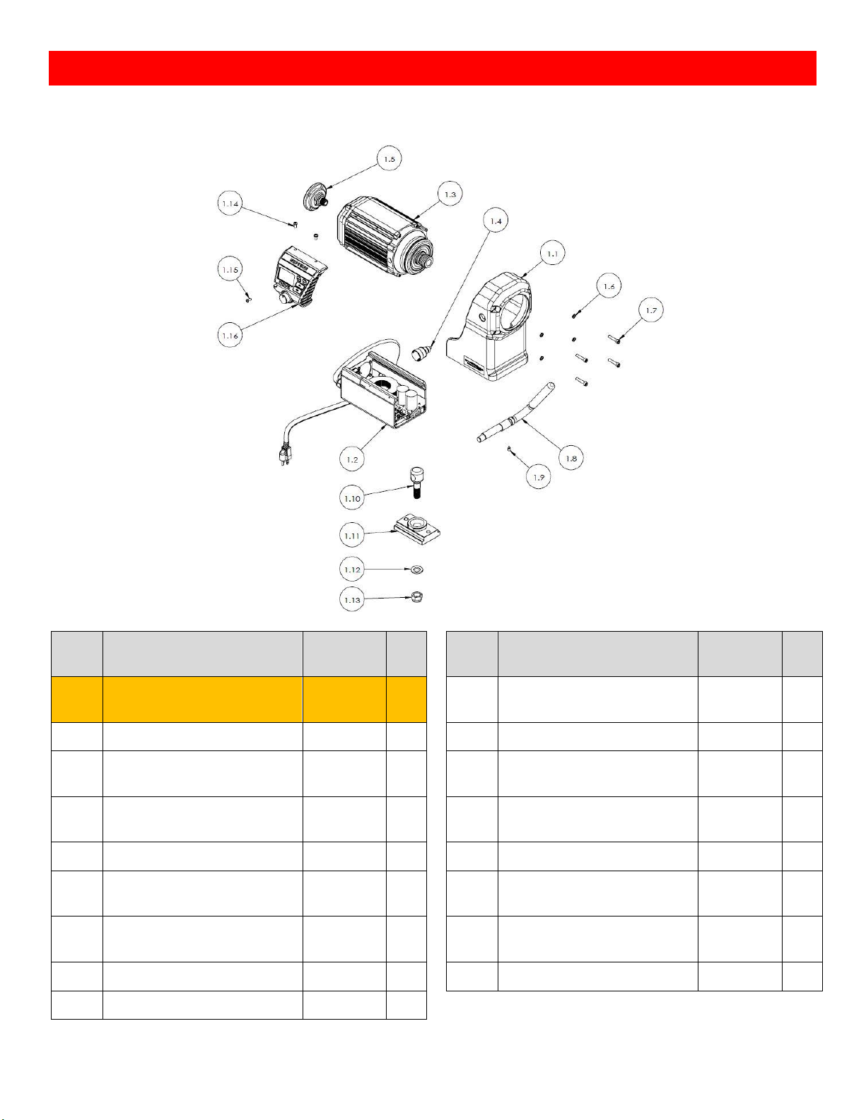
10. NOVA DVR Lathe Breakdown
NOVA DVR Headstock Breakdown
ITEM
NO.
DESCRIPTION
SKU
QTY.
ITEM
NO.
DESCRIPTION
SKU
QTY. 1 Headstock Assembly
5529013
1 1.9
Camshaft Set Screw M6x12mm -
Dog Point
G0612DE
1
1.1
Headstock Casting
5529127
1 1.10
Headstock Locking Boss
5529117
1
1.2
Controller Assembly
(US & CAN) / (AU & NZ & UK & EU)
5529015 /
5529174
1 1.11
Headstock Lock Plate
5529116
1
1.3
Motor Assembly
(EU) / (AU & NZ & US & CAN & UK)
5529172 /
5529016
1 1.12
Flat Washer M16
FW16
1
1.4
Spindle Lock Screw
5529121
1 1.13
Self-Locking Nut 304 Ø 16
LN16
1
1.5
Headstock Handwheel
5529128
1 1.14
HMI Top Mounting Screws
M5x10mm
MPB05010
2
1.6
Spring Washer M6
SW06
4 1.15
HMI Bottom Mounting Screws
M4x10mm
MPB0410
1
1.7
Mounting Screw M6x30mm
C06030
4 1.16
HMI Assembly
5529018
1
1.8
Headstock Camshaft Handle
5529115
1
Page 38
38
128-01-2310
128-0621-003
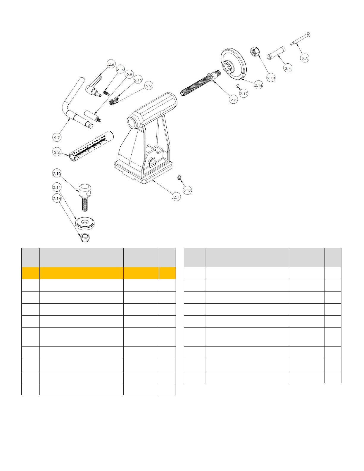
NOVA DVR Tailstock Breakdown
ITEM
NO.
DESCRIPTION
SKU
QTY.
ITEM
NO.
DESCRIPTION
SKU
QTY.
2
Tailstock Assembly
5529019
1 2.10
Tailstock Locking Boss
5569025
1
2.1
Tailstock Casting
5529160
1 2.11
Tailstock Lock Plate
5569043
1
2.2
Tailstock Quill
5529163
1 2.12
Quill Alignment Screw
SZ0820
1
2.3
Tailstock Quill Lead Screw
5529162
1 2.13
External Circlip 12mm
EC12
1
2.4
Tailstock Handwheel Handle
5699028
1 2.14
Self -Locking Nut 304 Ø 16
LN16
1
2.5
Tailstock Handwheel Handle Stud
Bolt
5699046
1 2.15
Alignment Screw Nut
5569043
1
2.6
Quill Locking Handle
5569040
1 2.16
Tailstock Handwheel 100mm
5529111
1
2.7
Tailstock Lock Camshaft
5529161
1 2.17
Tailstock Handwheel Key 6mm
5529165
1
2.8
Handle Stopper
5569024
1 2.18
Nylon Lock Nut M16
NHZ16
1
2.9
Quill Locking Nut
5529181
1
Page 39
39
128-01-2310
128-0621-003
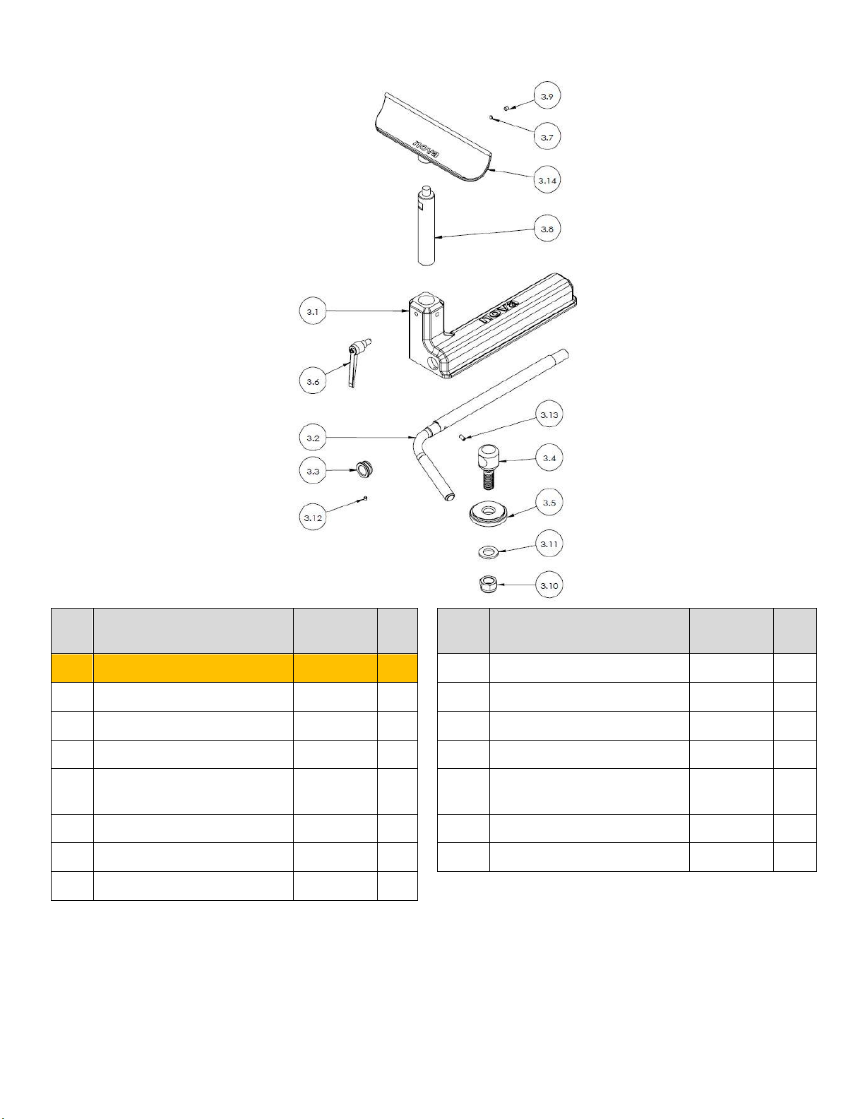
NOVA DVR Toolrest Breakdown
ITEM
NO.
DESCRIPTION
SKU
QTY.
ITEM
NO.
DESCRIPTION
SKU
QTY.
3
Toolslide Assembly
5529011
3.8
Toolrest Post 1 Inch
5529153
1
3.1
Toolslide Casting
5529102
1 3.9
Mounting Screw M6x6mm
SZ0606
1
3.2
Toolslide Lock Camshaft
5529103
1 3.10
Self -Locking Nut 304 Ø 16
LN16
1
3.3
Camshaft Ring
5529104
1 3.11
Flat Washer M16
FW16
1
3.4
Banjo Locking Boss
5529120
1 3.12
Mounting Screw M5x5mm
- Cone End
G0505CE
1
3.5
Toolslide Locking Plate
5529106
1 3.13
Mounting Screw M5x10mm
G0510
1
3.6
Toolrest Locking Handle
5529180
1 3.14
9 Inch Toolrest
5529167
1
3.7
Soft Washer
NS1000
1
Page 40
40
128-01-2310
128-0621-003
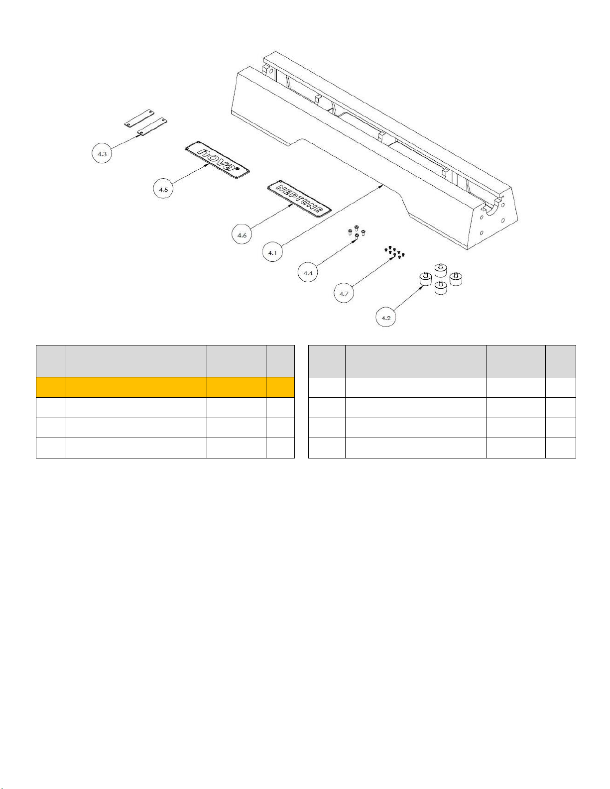
Neptune Bed Breakdown
ITEM
NO.
DESCRIPTION
SKU
QTY.
ITEM
NO.
DESCRIPTION
SKU
QTY.
4
Main Bed Assembly
1 4.4
Stopper Plate Screws M5x6mm
MPB0506
4
4.1
Main Bed
5529123
1 4.5
“NOVA” Name Plate
5529182
1
4.2
Feet Assembly
5529145
4 4.6
“NEPTUNE” Name Plate
5529166
1
4.3
End Stopper Plate
5569059
2 4.7
Name Plate Mounting Screws
MPB0305
8
Page 41
41
128-01-2310
128-0621-003
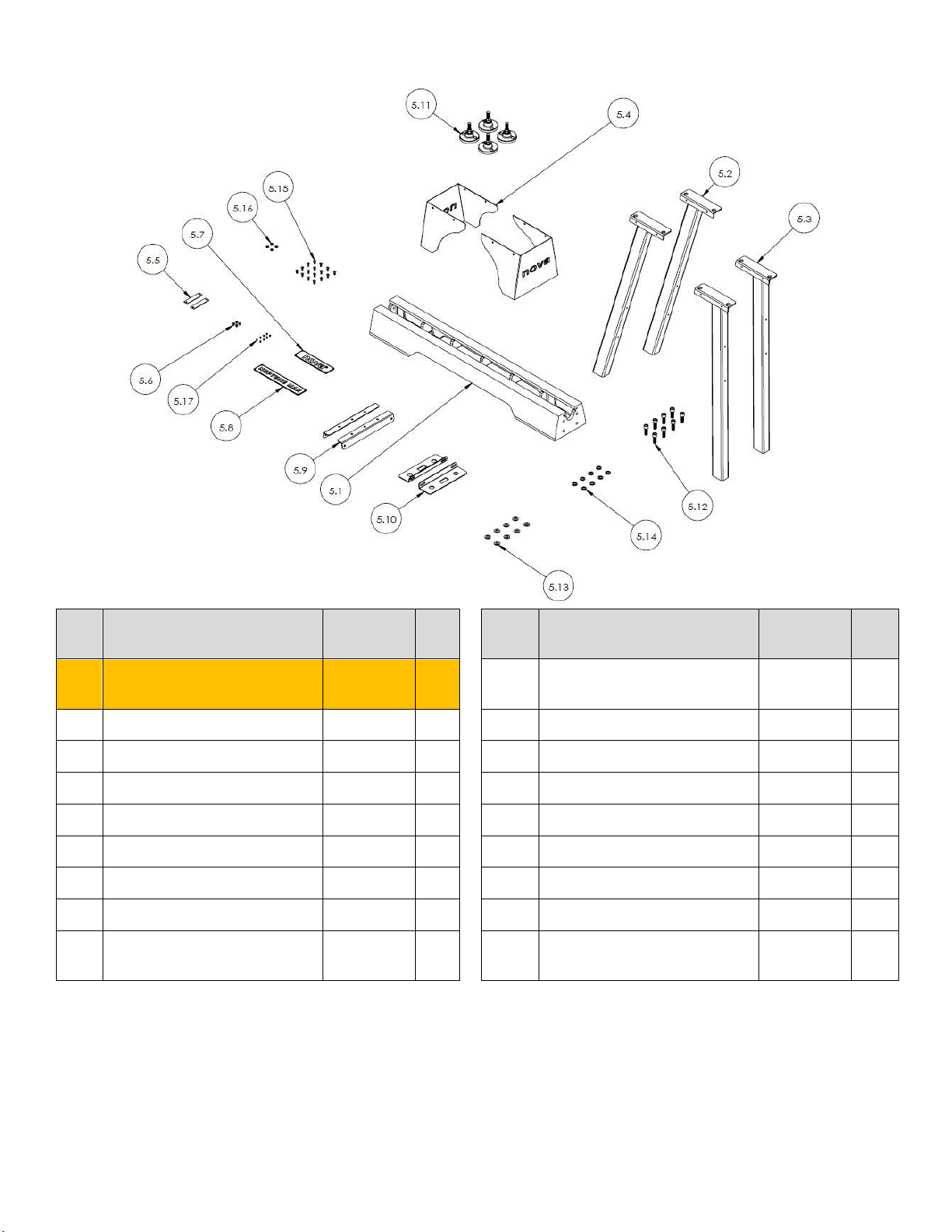
Neptune Max Bed & Stand Breakdown
ITEM
NO.
DESCRIPTION
SKU
QTY.
ITEM
NO.
DESCRIPTION
SKU
QTY.
5
Neptune Max Bed & Stand
Assembly
1 5.9
Stand Cross Plate
5519016
2
5.1
Main Bed
5519091
1 5.10
Stand Tool Tray
5519017
2
5.2
Stand Legs Set A
5519015
2 5.11
Foot Assembly
24161
4
5.3
Stand Legs Set B
5519020
2 5.12
Mounting Screws M12x35mm
C12035
8
5.4
Stand Cover
5519018
2 5.13
Flat Washer M12
FW12
8
5.5
End Stopper Plate
5569059
2 5.14
Spring Washer M12
SW12
8
5.6
Stopper Plate Screws M5x6mm
MPB0506
4 5.15
Button Head Cap Screw M6x12mm
BHC06012
16
5.7
“NOVA” Name Plate
5529182
1 5.16
Flat Washer M6
FW06
4
5.8
“NEPTUNE MAX” Name Plate
5519019
1 5.17
Name Plate Mounting Screws
M3x6mm
MPB0305
8
Page 42
42
128-01-2310
128-0621-003
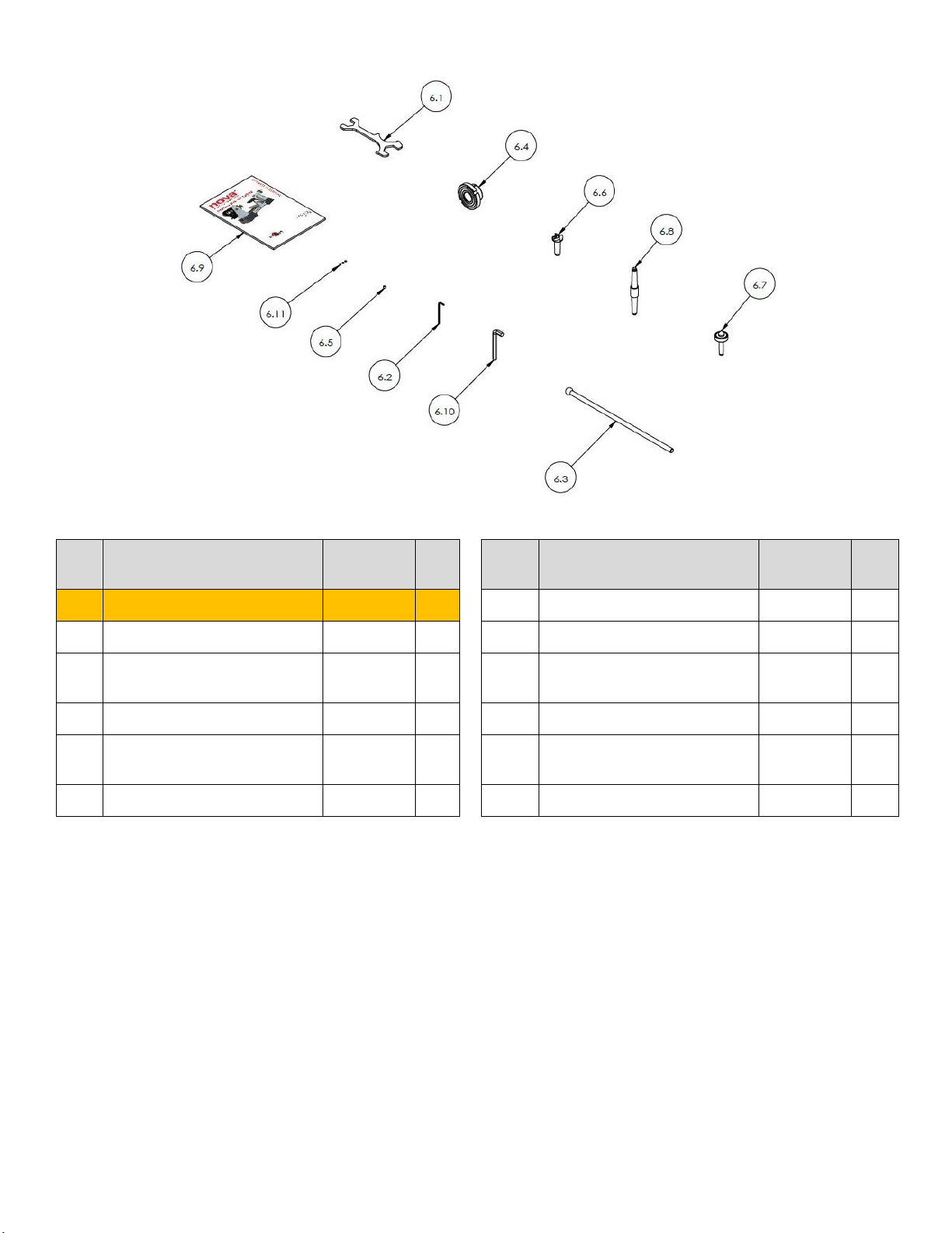
Accessories Breakdown
ITEM
NO.
DESCRIPTION
SKU
QTY.
ITEM
NO.
DESCRIPTION
SKU
QTY.
6
Accessories Pack
1 6.6
2MT Spur Centre
2MTSPUR
1
6.1
Universal Spanner
5568099
1 6.7
2MT Live Centre
2MTLC
1
6.2
3mm Allen Key
AK3
1 6.8
Double Ended Morse Taper –
Acruline Alignment Tool
2MTNA
1
6.3
Knock Out Bar
5529179
1 6.9
Neptune Manual
-
1
6.4
80mm Face Plate 1 ¼ 8tpi
(EU) / (AU & NZ & US & CAN & UK)
5529171 /
SFP80L
1 6.10
10mm Allen Key
(Neptune Max Model ONLY)
AK10
1
6.5
Set Screw M6x6mm
SZ0606
1 6.11
Soft Washer
NS1000
3
Page 43
43
128-01-2310
128-0621-003
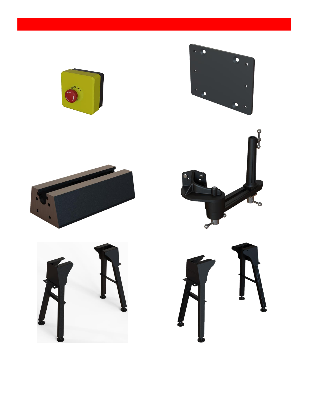
11. Optional Accessories
Emergency Stop
(SKU: 5529173)
Mounting Plate
(SKU: 5529168)
Bed Extension
(SKU: 5529125)
Outrigger
(SKU: 5519001)
Neptune Stand
(SKU: 5529169)
Neptune Max Stand
(SKU: 5529170)
Page 44
44
128-01-2310
128-0621-003
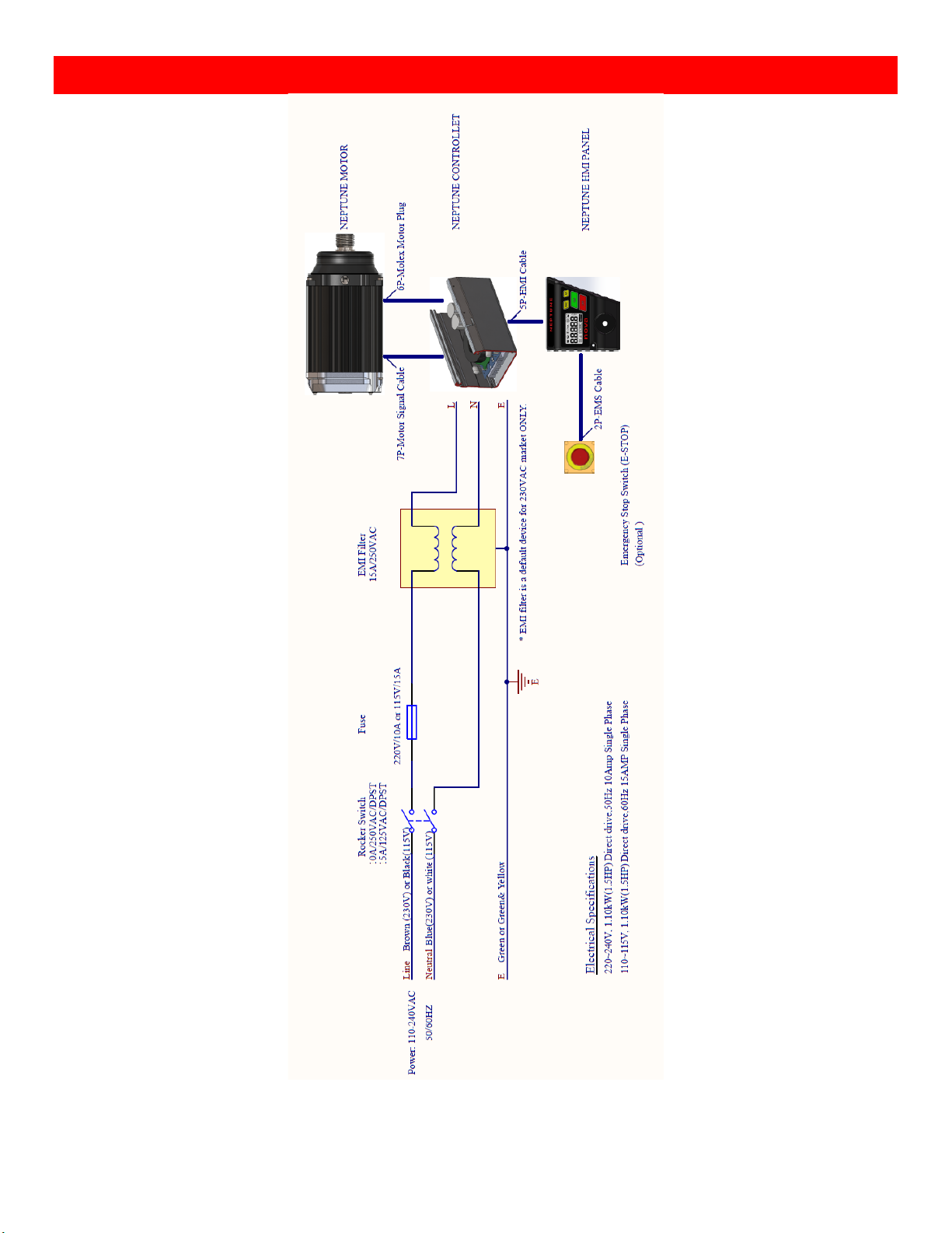
12.NOVA DVR Wiring Diagram
Page 45

45
128-01-2310
128-0621-003
CALIFORNIA RESIDENTS PROPOSITION 65
Attention California Residents
California’s Proposition 65 entitles California consumers to special warnings for products that contain chemicals known to the
state of California to cause cancer and birth defects or other reproductive harm if those products expose consumers to such
chemicals above certain threshold levels. We care about our customers’ safety and hope that the information below helps with
your buying decisions. The general Proposition 65 notice is as follows:
• WARNING: Drilling, sawing, sanding or machining wood products can expose you to wood dust, a
substance known to the State of California to cause cancer. Your risk from exposure to these chemicals varies,
depending on how often you do this type of work. To reduce your exposure, work in a well-ventilated area
and with approved safety equipment, such as dust masks that are specially designed to filter out microscopic
particles.
• WARNING: This product can expose you to chemicals (Rust Prevention Oil) which are known to the State of
California to cause cancer. Do not touch your eyes or face after unpacking until you have washed your hands.
It is advised to wear disposable gloves while unpacking and while cleaning the product down for first use.
Always unpack and clean in a well-ventilated area. Always wash your hands after unpacking the product for
first use. Dispose of packaging bags thoughtfully. Read the Safety Data Sheet for this Rust Protectant Oil
here: MSDS for rust protection
For more information go to www.P65Warnings.ca.gov
NOVA DVR 14.5” DVR Lathe Manual
© Teknatool® International 2022
All rights reserved. Teknatool® USA Inc.
Due to NOVA’s continuous product improvement and development policy, specifications, features
and images contained in this manual may change without notice. Teknatool is not responsible for
omissions or errors herein, or for incidental damages in connection with the furnishing of this
information.
 Loading...