

Page 1

Fire Alarm Control Panel
NFS-320/E/C,
NFS-320SYS/E
Operations Manual
Document 52747
06/16/2011 Rev:
P/N 52747:E1 ECN 11-336
E1
Page 2

Fire Alarm System Limitations
While a fire alarm system may lower insurance rates, it is not a substitute for fire insurance!
An automatic fire alarm system—typically made up of
smoke detectors, heat detectors, manual pull st ati ons, audib le
warning devices, and a fire alarm control panel with remote
notification capability—can provi de early warn ing of a develop
ing fire. Such a system, however, does not assure protection
against property damage or loss of life resulting from a fire.
The Manufacturer recommends that smoke and/or heat detectors be located throughout a protected premise following the
recommendations of the current edition of the National Fire
Protection Association S tandard 72 (NFPA 72), manufacturer's
recommendations, State and local codes, and the recommen
dations contained in the Guides for Proper Use o f System
Smoke Detectors, which are made available at no charge to all
installing dealers. These documents can be found at http://
www.systemsensor.com/html/applicat.html. A study by the
Federal Emergency Management Agency (an agency of the
United States government) indicated that smoke detectors
may not go off in as many as 35% of all fires. While fire al arm
systems are designed to provide early warning against fire,
they do not guarantee warning or protection against fire. A fire
alarm system may not provide timely or adequate warning, or
simply may not function, for a variety of reasons:
Smoke detectors may not sense fire where smoke cannot
reach the detectors such as in chimneys, in or behi nd walls, on
roofs, or on the other side of closed doors. Smoke detectors
also may not sense a fire on another level or floor of a building.
A second-floor detector, for example, may not sense a firstfloor or basement fire.
Particles of combustion or “smoke” from a developing fire
may not reach the sensing chambers of smoke detectors
because:
• Barriers such as closed or partially closed doors, walls, or
chimneys may inhibit particle or smoke flow.
• Smoke particles may become “cold,” stratify, and not reach
the ceiling or upper walls where detectors are located.
• Smoke particles may be blown away from detectors by air
outlets.
• Smoke particles may be drawn into air returns before
reaching the detector.
The amount of “smoke” present may be insufficient to alarm
smoke detectors. Smoke detectors are designed to alarm at
various levels of smoke density. If such density levels are not
created by a developing fire at the location of detectors, the
detectors will not go into alarm.
Smoke detectors, even when working properly, have sensing
limitations. Detectors that have photoelectronic sensing
chambers tend to detect smoldering fires better than flaming
fires, which have little visible smoke. Detectors that have ion
izing-type sensing chambers tend to detect fast-flaming fires
better than smoldering fires. Because fires d evelop in dif ferent
ways and are often unpredictable in their growth, neither type
of detector is necessarily best and a given type of detector
may not provide adequate warning of a fire.
Smoke detectors cannot be expected to provide adequate
warning of fires caused by arson, children playing with
matches (especially in bedrooms), smoking in bed, and violent
explosions (caused by escaping gas, improper storage of
flammable materials, etc.).
Heat detectors do not sense particles of combustion and
alarm only when heat on their sensors incre ases at a predete r
mined rate or reaches a predetermined level. Rate-of-rise
heat detectors may be subject to reduced sensitivity over t ime.
For this reason, the rate-of-rise feature of each detector
should be tested at least once per year by a qualified fire pro
tection specialist. Heat detectors are designed to protect
property, not life.
IMPORTANT! Smoke detectors must be installed in the
same room as the control panel and in rooms used by the sys
tem for the connection of alarm transmission wiring, communications, signaling, and/or power. If detectors are not so
located, a developing fire may damage the alarm system, crip
pling its ability to report a fire.
Audible warning devices such as bells may not alert people
if these devices are located on the other side of closed or
partly open doors or are located on another floor of a building .
Any warning device may fail to alert people with a disability or
those who have recently consumed drugs, alcohol or medica
-
tion. Please note that:
• Strobes can, under certain circumstances, cause seizures
in people with conditions such as epilep sy.
• Studies have shown that certain people, even when they
hear a fire alarm signal, do not respond or comprehend the
meaning of the signal. It is the property owner's responsi
bility to conduct fire drills and other training exercise to
make people aware of fire alarm signals and instruct them
on the proper reaction to alarm signals.
• In rare instances, the sounding of a warning device can
cause temporary or permanent hearing loss.
A fire alarm system will not operate without any electrical
power. If AC power fails, the system will operate from st and by
batteries only for a specified time and only if the batteries have
been properly maintained and replaced regularly.
Equipment used in the system may not be technically compatible with the control panel. It is essential to use only equipment listed for service with your control panel.
Telephone lines needed to transmit alarm signals from a
premise to a central monitoring station may be out of service
or temporarily disabled. For added protection against tele
phone line failure, backup radio transmission systems are recommended.
The most common cause of fire alarm malfunction is inadequate maintenance. To keep the entire fire alarm system in
excellent working order, ongoing maintenance is required per
the manufacturer's recommendations, and UL and NFPA stan
dards. At a minimum, the requirements of NFPA 72 shall be
followed. Environments with large amounts of dust, dirt or
high air velocity require more frequent maintenance. A main
tenance agreement should be arranged through the local manufacturer's representative. Maintenance should be scheduled
monthly or as required by National and/or local fire codes and
should be performed by authorized professional fire alarm
installers only. Adequate written records of all inspections
should be kept.
Limit-C1-2-2007
2 NFS-320/E/C, NFS-320SYS/E Operations Manual — P/N 52747:E1 06/16/2011
Page 3

Installation Precautions
Adherence to the following will aid in problem-free installation with long-term reliability:
WARNING - Several different sources of power can be
connected to the fire alarm control panel. Disconnect all
sources of power before servicing. Control unit and associ
ated equipment may be damaged by removing and/or inserting cards, modules, or interconnecting cables while the unit is
energized. Do not attempt to install, service, or operate this
unit until manuals are read and understood.
CAUTION - System Re-acceptance Test after Software
Changes: To ensure proper system operation, this product
must be tested in accordance with NFPA 72 after any pro
gramming operation or change in site-specific software. Reacceptance testing is required after any change, addition or
deletion of system components, or after any modification,
repair or adjustment to system hardware or wiring. All compo
nents, circuits, system operations, or sof tware functions known
to be affected by a change must be 100% tested. In addit ion,
to ensure that other operations are not inadvertently affected,
at least 10% of initiating devices that are not directly affected
by the change, up to a maximum of 50 devices, must also be
tested and proper system operation verified.
This system meets NFPA requirements for operation at 0-49º
C/32-120º F and at a relative humidity 93% ± 2% RH (non
condensing) at 32°C ± 2°C (90°F ± 3°F). However, the useful
life of the system's standby batteries and the electronic com
ponents may be adversely affected by extreme temperature
ranges and humidity. Therefore, it is recommended that this
system and its peripherals be installed in an environment with
a normal room temperature of 15-27º C/60-80º F.
Verify that wire sizes are adequate for all initia ting and indicating device loops. Most devices cannot tol erate more than a
10% I.R. drop from the specified device voltage.
Like all solid state electronic devices, this system may
operate erratically or can be damaged when subject ed to light
ning induced transients. Although no system is completely
immune from lightning transients and interference, proper
grounding will reduce susceptibility. Overhead or outside aerial
wiring is not recommended, due to an increased susceptibility
to nearby lightning strikes. Consult with the Technical Ser
vices Department if any problems are anticipated or encountered.
Disconnect AC power and batteries prior to removing or
inserting circuit boards. Failure to do so can damage circuits.
Remove all electronic assemblies prior to any drilling, filing,
reaming, or punching of the enclosure. When possible, make
all cable entries from the sides or rear. Before making modifi
cations, verify that they will not interfere with battery, transformer, or printed circuit board location.
Do not tighten screw terminals more than 9 in-lbs. Overtightening may damage threads, resulting in reduced terminal
contact pressure and difficulty wit h screw terminal removal.
This system contains static-sensitive components.
Always ground yourself with a proper wrist strap before han
dling any circuits so that static charges are removed from the
body. Use static suppressive packaging to protect electronic
assemblies removed from the unit.
Follow the instructions in the inst al lati on, opera ting, and pr ogramming manuals. These instructions must be followed to
avoid damage to the control panel and associated equipment.
FACP operation and rel iability depend upon prop er inst allatio n.
Precau-D1-9-2005
FCC Warning
WARNING: This equipment generates, uses, and can
radiate radio frequency energy and if not installed and
used in accordance with the instruction manual may
cause interference to radio communications. It has been
tested and found to comply with the limits for class A
computing devices pursuant to Subpart B of Part 15 of
FCC Rules, which is designed to provide reasonable
protection against such interference when devices are
operated in a commercial environment. Operation of this
equipment in a residential area is likely to cause interference, in which case the user will be required to correct
the interference at his or her own expense.
Canadian Requirements
This digital apparatus does not exce ed the Class A limit s
for radiation noise emissions from digital apparatus set
out in the Radio Interference Regulations of the Canadian Department of Communications.
Le present appareil numerique n'emet pas de bruits
radioelectriques depassant les limites applicables aux
appareils numeriques de la classe A prescrites dans le
Reglement sur le brouillage radioelectrique edict e p ar l e
ministere des Communications du Canada.
HARSH™, NIS™, and NOTI•FIRE•NET™ are all trademarks; and Acclimate® Plus, FlashScan®, NION®, NOTIFIER®, ONYX®, ONYXWorks®, UniNet®,
VeriFire®, and VIEW® are all registered trademarks of Honeywell International Inc. Echelon® is a registered trademark and LonWorks™ is a trademark of
Echelon Corporation. ARCNET® is a registered trademark of Datapoint Corporation. Microsoft® and Windows® are registered trademarks of the Microsoft
Corporation.
©2011 by Honeywell International Inc. All rights reserved. Unauthorized use of this document is strictly prohibited.
NFS-320/E/C, NFS-320SYS/E Operations Manual — P/N 52747:E1 06/16/2011 3
Page 4

Software Downloads
In order to supply the latest features and functionality in fire alarm and life safety technology to our customers, we make
frequent upgrades to the embedded software in our products. To ensure that you are installing and programming the latest
features, we strongly recommend that you download the most current version of software for each product prior to
commissioning any system. Contact T echnical Support with any questions about software and the appropriate version for
a specific application.
Documentation Feedback
Your feedback helps us keep our documentation up-to-date and accurate. If you have any comments or suggestions about
our online Help or printed manuals, you can email us.
Please include the following information:
•Product name and version number (if applicable)
•Printed manual or online Help
•Topic Title (for online Help)
•Page number (for printed manual)
•Brief description of content you think should be improved or corrected
•Your suggestion for how to correct /improve documentation
Send email messages to:
Please note this email address is for documentation feedback only. If you have any technical issues, please contact
Technical Services.
4 NFS-320/E/C, NFS-320SYS/E Operations Manual — P/N 52747:E1 06/16/2011
Page 5

Table of Contents
Section 1: General Information................................................................................................8
1.1: UL 864 Compliance.......................................................................................................................................8
1.2: About This Manual........................................................................................................................................8
1.2.1: Cautions and Warnings........................................................................................................................8
1.2.2: Typographic Conventions....................................................................................................................8
1.2.3: Supplemental Information...................................................................................................................9
1.2.4: Shortcuts to Operating Functions......................................................................................................10
1.3: Introduction to the Control Panel ................................................................................................................10
Section 2: Use of the Controls...............................................................................................11
2.1: Introduction..................................................................................................................................................11
2.2: System Status Indicator LEDs.............................................................. .......................................................11
2.3: Control Keys................................................................................................................................................12
2.3.1: Acknowledge/Scroll Display.............................................................................................................12
2.3.2: Signal Silence....................................................................................................................................13
2.3.3: System Reset .....................................................................................................................................13
2.3.4: Drill....................................................................................................................................................14
2.3.5: Lamp Test..........................................................................................................................................14
2.4: Programming Keypad..................................................................................................................................14
Section 3: Operation of the Control Panel............................................................................16
3.1: Overview......................................................................................................................................................16
3.2: Normal Mode of Operation .........................................................................................................................16
3.3: Fire Alarm Mode of Operation....................................................................................................................17
3.3.1: How the Control Panel Indicates a Fire Alarm..................................................................................17
3.3.2: How to Respond to a Fire Alarm.......................................................................................................17
3.3.3: Interpreting Fire Alarm Type Codes .................................................................................................18
3.4: Carbon Monoxide (CO) Alarm Mode of Operation....................................................................................20
3.4.1: How the Control Panel Indicates a CO Alarm ..................................................................................20
3.4.2: How to Respond to a CO alarm.........................................................................................................20
3.4.3: Interpreting CO Alarm/Supervisory Type ID Codes.........................................................................21
3.5: System Trouble Mode of Operation ............................................................................................................21
3.5.1: How the Control Panel Indicates a System Trouble..........................................................................21
3.5.2: How to Respond to a System Trouble...............................................................................................22
3.6: Security Alarm Mode of Operation.............................................................................................................23
3.6.1: How the Control Panel Indicates a Security Alarm...........................................................................23
3.6.2: How to Respond to a Security Alarm................................................................................................23
3.6.3: Interpreting Security Type Codes......................................................................................................24
3.7: Active Supervisory Signal Mode of Operation ...........................................................................................24
3.7.1: How the Control Panel Indicates an Active Supervisory ..................................................................24
3.7.2: How to Respond to an Active Supervisory .......................................................................................25
3.7.3: How to Interpret Supervisory Type Codes........................................................................................25
3.8: Pre-Alarm Warning Mode of Operation......................................................................................................26
3.8.1: How the Control Panel Indicates a Pre-Alarm Warning ...................................................................26
3.8.2: How to Respond to a Pre-Alarm Warning.........................................................................................27
3.9: Disabled Points Mode of Operation ............................................................................................................28
3.10: Non-Alarm Mode of Operation ....................................................... ..........................................................28
3.10.1: Purpose of Non-Alarm Points..........................................................................................................28
3.10.2: How the Control Panel Indicates an Active Fire Control................................................................29
3.10.3: How the Control Panel Indicates an Active Non-Fire Point .... .......................................................29
3.11: Active Trouble Monitor Mode of Operation..............................................................................................29
3.11.1: How the Control Panel Indicates an Active Trouble Monitor .........................................................29
3.11.2: How to Respond to an Active Trouble Monitor..............................................................................30
3.12: Output Circuit Trouble Mode of Operation...............................................................................................30
3.12.1: Overview ............................................................................................. ............................................30
NFS-320/E/C, NFS-320SYS/E Operations Manual — P/N 52747:E1 06/16/2011 5
Page 6

Table of Contents
3.12.2: How the Control Panel Indicates a NAC Trouble ...........................................................................31
3.12.3: How the Control Panel Indicates a Control/Relay Trouble.............................................................31
3.12.4: How to Respond to a NAC or Control/Relay Trouble ....................................................................32
3.13: Operation of Special System Timers .........................................................................................................32
3.13.1: What are System Timers?................................................................................................................32
3.13.2: How to View System Timer Selections...........................................................................................32
3.13.3: How System Timers Work ..............................................................................................................32
3.14: Waterflow Circuit Operation......................................................................................................................33
3.15: Style 6 and Style 7 Operation ....................................................................................................................33
Section 4: Read Status Operation.........................................................................................34
4.1: Introduction..................................................................................................................................................34
4.2: What is Read Status?........................ .................................. .................................. ........................................34
4.2.1: Quick Reference Key Sequences.......................................................................................................34
4.3: Entering Read Status.................................... ................................................................................................34
4.4: Viewing and Printing a Read Status.............................................................................................................35
4.4.1: How to View Read Status of Devices, Zones, & System Settings....................................................35
4.4.2: How to View Read Status for Event and Alarm History...................................................................44
4.4.3: How to Print Points, Event and Alarm History .................................................................................45
4.4.4: How to View and Print Hidden Event and Alarm History................................................................47
Appendix A: Special Zone Operation ...................................................................................49
A.1: Overview.....................................................................................................................................................49
A.2: Releasing Zones (R0-R9)............................................................................................................................49
A.2.1: Purpose of Releasing Zones .............................................................................................................49
A.2.2: How to View Releasing Zone Selections .........................................................................................50
A.2.3: How Releasing Zones Operate .........................................................................................................50
A.3: Time, Date, and Holiday Functions............................................................................................................52
A.3.1: Overview...........................................................................................................................................52
A.3.2: How to View Time Control Selections.............................................................................................52
A.3.3: How to View Holiday Function Selections ......................................................................................53
A.3.4: How Time Control and Holiday Functions Work ............................................................................53
A.4: NAC Coding ...............................................................................................................................................54
A.4.1: Overview of Coding..........................................................................................................................54
A.4.2: How to View Coding (F8) Selections...............................................................................................54
A.4.3: How to Respond to an Alarm with Coding.......................................................................................55
A.5: Presignal and Positive Alarm Sequence (PAS) Operation..........................................................................55
A.5.1: Overview...........................................................................................................................................55
A.5.2: What is Presignal and PAS? .............................................................................................................55
A.5.3: How to View Presignal and PAS Selections ....................................................................................56
A.5.4: How to Respond to an Alarm with Presignal Delay Timer (no PAS)..............................................56
A.5.5: How to Respond to an Alarm with Presignal Delay Timer (PAS selected) .....................................57
Appendix B: Intelligent Detector Functions........................................................................58
Appendix C: Remote Terminal Access.................................................................................60
C.1: General Description.....................................................................................................................................60
C.2: Operating Modes.........................................................................................................................................60
C.2.1: Local Terminal Mode (LocT)...........................................................................................................60
C.2.2: Local Monitor Mode (LocM)............................................................................................................61
C.2.3: Remote Terminal Mode (RemT).......................................................................................................61
C.3: Using the CRT-2 for Read Status ................................................................................................................62
C.3.1: Overview...........................................................................................................................................62
C.3.2: Accessing Read Status Options.........................................................................................................62
C.3.3: Read Point.........................................................................................................................................63
C.3.4: Display Devices in Alarm or Trouble...............................................................................................63
C.3.5: Display All Programmed Points .......................................................................................................64
C.3.6: Step-through History .........................................................................................................................64
6 NFS-320/E/C, NFS-320SYS/E Operations Manual — P/N 52747:E1 06/16/2011
Page 7

Table of Contents
C.3.7: View All History...............................................................................................................................64
C.3.8: Step-through Alarm History .............................................................................................................64
C.3.9: View All Alarm History....................................................................................................................64
C.4: Using the CRT-2 for Alter Status ................................................................................................................64
C.4.1: Overview...........................................................................................................................................64
C.4.2: Accessing Alter Status Options ........................................................................................................65
C.4.3: Enable or Disable Detectors, Modules or Zones ..............................................................................65
C.4.4: Change Alarm and Pre-Alarm Levels...............................................................................................66
C.4.5: Clear Verification Counter................................................................................................................66
C.4.6: Clear the Entire History Buffer................................. .. ......................................................................66
C.4.7: Set the Pre-Alarm for Alert or Action...............................................................................................67
Appendix D: Point and System Troubles Lists....................................................................68
D.1: Point (Device) Troubles ..............................................................................................................................68
D.2: System Troubles..........................................................................................................................................69
Index.........................................................................................................................................72
NFS-320/E/C, NFS-320SYS/E Operations Manual — P/N 52747:E1 06/16/2011 7
Page 8

Section 1: General Information
!
!
1.1 UL 864 Compliance
This product has been certified to comply with the requirements in the Standard for Control Units
and Accessories for Fire Alarm Systems, UL 864 9th Edition.
1.2 About This Manual
1.2.1 Cautions and Warnings
This manual contains cautions and warnings to alert the reader as follows:
CAUTION:
Information about procedures that could cause programming errors, runtime errors, or equipment
damage.
WARNING:
Indicates information about procedures that could cause irreversible damage to the control panel,
irreversible loss of programming data or personal injury.
1.2.2 Typographic Conventions
This manual uses the following typographic conventions as listed in below:
When you see Specifies Example
text in small caps the text as it appears in the
LCD display or on the control
panel
text in quotes a reference to a section or a
LCD menu screen
bold text In body text, a number or
character that you enter
italic text a specific document NFS-320 Installation Manual
a graphic of the key In a graphic, a key as it
appears on the control panel
Table 1.1 Typographic Conventions in this Manual
NOTE: In this manual, the term NFS-320 is used to refer to the NFS-320, NFS-320E, and
NFS-320C, NFS-320SYS and NFS-320SYS/E unless otherwise noted.
MARCH TIME is a selection that appears in the
LCD display; or Press the
“Read Status”; specifies the Read S tatus section
or menu screen
Press 1; means to press the number “1” on the
keypad
Press means to press the Escape key
ENTER key
8 NFS-320/E/C, NFS-320SYS/E Operations Manual — P/N 52747:E1 06/16/2011
Page 9

About This Manual General Information
1.2.3 Supplemental Information
The table below provides a list of documents referenced in this manual, as well as documents for
selected other compatible devices. The document series chart (DOC-NOT) provides the current
document revision. A copy of this document is included in every shipment.
Compatible Conventional Devices (Non-addressable) Document Number
Device Compatibility Document 15378
Fire Alarm Control Panel (FACP) and Main Power Supply Installation Document Number
NFS-320/E/C Installation, Operations, and Programming Manuals
NFS-320C Canadian Applications Addendum
NFS-320SYS/E/C Installation Manual 53717
SLC Wiring Manual 51253
Note: For individual SLC Devices, refer to the SLC Wiring Manual
Off-line Programming Utility Document Number
VeriFire® Tools CD help file VERIFIRE-TCD
Power Supplies, Auxiliary Power Supplies & Battery Chargers Document Number
ACPS-2406 Installation Manual 51304
ACPS-610 Instruction Manual 53018
APS-6R Instruction Manual 50702
APS2-6R Instruction Manual 53232
CHG-120 Battery Charger Manual 50641
FCPS-24S6/FCPS-24S8 Field Charger/Power Supply Manual 51977
Networking Document Number
High-Speed Network Communication Module 54014
High-Speed Noti•Fire•Net Instruction Manual 54013
Noti•Fire•Net Manual, Network Version 5.0 & Higher 51584
ONYXWorks™ Workstation Hardware & Software Application: Installation and Operation Manual 52342
ONYXWorks™ NFN Gateway (PC Platform) Installation & Operation Manual 52307
ONYXWorks™ NFN Gateway (Embedded Platform) Installation & Operation Manual 52306
NCM-W/F Installation Document 51533
NCS ONYX® Network Control Station Manual, Network Version 4.0 & Higher 51658
NCA-2 Network Control Annunciator Manual 52482
NCA Network Control Annunciator Manual 51482
System Components Document Number
Annunciator Control System Manual 15842
ACM-8R Annunciator Control Module Manual 15342
FDU-80 Remote Annunciator Manual 51264
LCD-80 Liquid Crystal Display Annunciator 15037
LCD2-80 Liquid Crystal Display Annunciator 53242
LDM Series Lamp Driver Annunciator Manual 15885
SCS Smoke Control Manual (Smoke and HVAC Control Station) 15712
DPI-232 Direct Panel Interface Manual 51499
TM-4 Installation Document (Reverse Polarity Transmitter) 51490
UDACT Manual (Universal Digital Alarm Communicator/Transmitter) 50050
FireVoice-25/50 & FireVoice-25/50ZS Manual 52290
RA100Z Remote LED Annunciator Installation Document I56-0508
52745, 52746, 52747
52745CDN
Table 1.2 Supplemental Documentation
NFS-320/E/C, NFS-320SYS/E Operations Manual — P/N 52747:E1 06/16/2011 9
Page 10

General Information Introduction to the Control Panel
1.2.4 Shortcuts to Operating Functions
T o the left of each program function, you’ll find a keypad shortcut, which contains a
series of keypad entries required to access the program function. All shortcuts start
with the control panel in normal operation.
For example, the keypad shortcut to the left, shows how to enter the Read Status
function with the control panel in normal operation, as well as how to exit the
function.
1.3 Introduction to the Control Panel
The NFS-320 is a modular, intelligent Fire Alarm Control Panel (FACP) with features suitable for
most applications. Following is a list of operating features available.
• Alarm Verification selection, to reduce unwanted alarms, for intell igent detector points
• Positive Alarm Sequence (PAS) and Presignal per NFPA 72
• Silence Inhibit timer and Auto Silence timer for Notification Appliance Circuits (NACs)
• March time/temporal code for Notification Appliance Circuits (NACs)
• Programmable Signal Silence, System Reset, and Alarm Activate functions through monitor
modules
• Automatic time-of-day and day-of-week control functions, with holiday option
• Intelligent Sensing with nine field-adjustable Pre-Alarm levels with programmable
Control-By-Event (CBE)
• Operate automatic smoke or heat detector sounder base on action Pre-Alarm level, with
general evacuation on alarm level
• Security alarm point option with separate audible signal code
• Audible alarm signaling options
• Programmable Control-By-Event control of outputs from individual alarm or supervisory
addressable devices
• Networks with other FACPs and equipment for large applications.
10 NFS-320/E/C, NFS-320SYS/E Operations Manual — P/N 52747:E1 06/16/2011
Page 11

Section 2: Use of the Controls
Control Keys
(Refer to
page 12).
Status Indicator
LEDs (Refer to
Section 2.2 below)
Programming Keypad
(Refer to page 14
Function keys
(Refer to page 14
Cursor movement (arrow) keys,
ESC key, and ENTER key. (Refer to page 14
NFS2_640-keypad.wmf
80-character (2 x 40) Liquid Crystal
Display.(LCD)
2.1 Introduction
Listing of the controls and indicators and where to find information on their use:
Operating Components Covered in
Twelve System Status Indicator LEDs “System Status Indicator LEDs” on page 11
Five Control Keys “Control Keys” on page 12
Programming Keypad “Programming Keypad” on page 14
Figure 2.1 NFS-320 Control Panel Keys and Indicators
2.2 System Status Indicator LEDs
The control panel contains 12 labeled LEDs described in Table 2.1.
Indicator Color When Active To Turn Of f
CONTROLS
ACTIVE
POWER Green Lights when the proper primary AC power is
Green LIghts when the panel assumes control of local
operation as primary display.
applied. Remains lit while power is applied.
Turns off automatically when another panel
assumes control of local operation.
Always lit with AC power applied.
Table 2.1 Descriptions of System Status Indicator LEDs (1 of 2)
NFS-320/E/C, NFS-320SYS/E Operations Manual — P/N 52747:E1 06/16/2011 11
Page 12

Use of the Controls Control Keys
Indicator Color When Active To Turn Off
PRE-DISCHARGE Red Lights when any of the releasing zones have been
activated, but have not yet discharged a releasing
agent.
DISCHARGE Red Lights when any of the releasing zones are active
and in the process of discharging a releasing
agent.
ABORT ACTIVE Yellow Lights when an abort switch has been activated.
FIRE ALARM Red Flashes when a non-acknowledged fire alarm
exists. Lights steadily after you acknowledge the
fire alarm.
PRE-ALARM Red Flashes when a non-acknowledged fire Pre-Alarm
exists. Lights steadily after you acknowledge the
Pre-Alarm.
Turns off automatically when no releasing
zones are in the pre-discharge state.
Turns off automatically when no releasing
zones are discharging a releasing agent.
*
Turns off automatically when an abort switch
has been pressed and its timer is still
counting down.
Clear the alarm condition and reset the
system.
Clear the pre-alarm condition. (An Action
Pre-Alarm requires a system reset.)
SECURITY Blue Flashes when a non-acknowledged Security alarm
SUPERVISORY Yellow Flashes when a non-acknowledged Supervisory
SYSTEM
TROUBLE
SIGNALS
SILENCED
POINT
DISABLED
Yellow Flashes when a non-acknowledged system trouble
Yellow Lights steadily after a fire alarm condition occurs
Yellow Lights when one or more system devices are
exists. Lights steadily after you acknowledge the
alarm.
condition exists. Lights steadily after you
acknowledge the event.
exists. Lights steadily after you acknowledge the
trouble.
and after you press
outputs. Flashes to indicate that some
silenceable outputs are on and some are off.
disabled.
SIGNAL SILENCE to silence all
Clear the Security alarm condition and reset
the system.
Clear the condition (Supervisory inputs
require a system reset if they are latching.
Refer to
information.).
Clear the trouble condition.
Press SYSTEM RESET. DRILL will also turn off
the LED.
Enable the device or remove the disabled
device from the system program.
Table 3.4 page 26 for latching
Table 2.1 Descriptions of System Status Indicator LEDs (2 of 2)
* Activation of a Manual Release Switch will overri de Predischarge Delay and override an active Abort
Release Switch, resulting in an immediate agent release.
2.3 Control Keys
The control panel provides five Control Keys as described below:
2.3.1 Acknowledge/Scroll Display
Use the ACKNOWLEDGE/SCROLL DISPLAY key to respond to new alarm or trouble signals. When
pressed, the control panel does the following:
• Silences the panel sounder
• Changes all active LED indicators from flashing to steady
• Sends an Acknowledge message to the History buffer and installed printers, CRT-2 terminals,
and FDU-80 annunciators
• Sends a signal to silence the sounders on the FDU-80 and ACS annunciators
12 NFS-320/E/C, NFS-320SYS/E Operations Manual — P/N 52747:E1 06/16/2011
Page 13

Control Keys Use of the Controls
You can also press this key to display multiple alarms or troubles. If more than one alarm or trouble
exists, the control panel displays the next alarm or trouble for 3 seconds (or until you press the
ACKNOWLEDGE/SCROLL DISPLAY key), then displays the next alarm or trouble.
NOTE: If Local Control is set to “0” (NO), the FACP will not respond to ACKNOWLEDGE, and the
piezo will not sound.
2.3.2 Signal Silence
Use the SIGNAL SILENCE key to silence the panel sounder and turn off all audio and visual devices
connected to Notification Appliance Circuits. When pressed, the control panel does the following:
• Turns off the panel sounder
• Turns off all silenceable output circuits
•Lights the SIGNALS SILENCED LED
• Sends a SIGNALS SILENCED message to the History buffer and installed printers, CRT-2
terminals, and FDU-80 annunciators
Partial Signal Silence
When some active outputs are silenced and others remain constant, the SIGNALS SILENCED LED
will flash
NOTE: If Local Control is set to “0” (NO) or “2” (Partial Control), the FACP will not respond to
SIGNAL SILENCE.
2.3.3 System Reset
Use the SYSTEM RESET key to reset the control panel. When pressed, the control panel does the
following:
• Clears ALL active inputs
• Interrupts resettable power
• Sends a “System Reset” message to the History buffer, and installed printers, CRT-2 terminals,
and FDU-80 annunciators
• Decouples from Noti•Fire•Net, if connected, for 60 seconds to allow Cooperative Control By
Event (CCBE) to clear.
If any alarm or trouble exists after you press the SYSTEM RESET key, all NACs, contr ol output s, and
panel audio and visual indicators will reactivate.
NOTE: Trouble conditions will not clear and re-report upon reset.
NOTE: If Local Control is set to “0” (NO), the FACP will not respond to SYSTEM RESET.
NFS-320/E/C, NFS-320SYS/E Operations Manual — P/N 52747:E1 06/16/2011 13
Page 14

Use of the Controls Programming Keypad
2.3.4 Drill
Use the DRILL key to manually activate all silenceable outputs and Notification Appliance Circuits.
To prevent accidental activation, you must press the
control panel does the following:
• Turns on all silenceable NACs
• Turns off the SIGNALS SILENCED LED
• Sends a Manual Evacuate message to the History buffer and installed printers, CRT-2
terminals, and FDU-80 annunciators
NOTE: If Local Control is set to “0” (NO) or “2” (Partial Control), the FACP will not respond to
DRILL.
DRILL key for 2 seconds. When pressed, the
2.3.5 Lamp Test
Use the LAMP TEST key to test the control panel LEDs and the panel sounder. When pressed and
held, the control panel does the following:
• Lights all control panel LEDs
• Turns on the panel sounder
• Lights all segments of the LCD display. When the LAMP TEST key is held for longer than five
seconds, the LCD will display the Software Revisions.
2.4 Programming Keypad
The programming keypad includes:
• Function keys: DETECTOR, MODULE, OUTPUT, BATTERY LEVELS, NEXT SELECTION, PREVIOUS
SELECTION, RECALL LAST ENTRY, and INCREMENT NUMBER
• ENTER key
• Cursor movement keys: ESC/LEFT ARROW key, UP key, RIGHT key, DOWN key
• Alphabetic and numeric keys, with LOWER CASE selection key
Shown below is the Programming Keypad, with descriptions for the keys.
14 NFS-320/E/C, NFS-320SYS/E Operations Manual — P/N 52747:E1 06/16/2011
Page 15

Programming Keypad Use of the Controls
LOWER CASE key – press
with an alphabetic key to
enter lower case characters
DETECTOR key – press
to select a detector
OUTPUT key – press to select a
Notification Appliance Circuit
MODULE key – press to select a
control/relay or monitor module
NEXT SELECTION key – press to display the next item in a list
or display the device at the next highest address
PREVIOUS SELECTION key – press to display the previous item
in a list or display the device at the next lowest address
Arrow keys – press to move the cursor
one place in the direction of the arrow
ESC key – press to exit a selection or
move the cursor one place to the left
ENTER key – press to complete
or save an entry. Also press to
enter Programming
Numeric keys – press to enter
numeric characters. Press with
Lower Case key for symbols.
Alphabetic keys – press to enter
alphabetic characters
S
PACE – press to enter a space
NFS640-keypad3.cdr
BATTERY LEVELS key – press
to check the voltage and
charging status of the
batteries.
NFS-320/E/C, NFS-320SYS/E Operations Manual — P/N 52747:E1 06/16/2011 15
Figure 2.2 Programming Keypad
Page 16

Section 3: Operation of the Control Panel
!
SYSTEM NORMAL 01:56P 041511 Tue
3.1 Overview
This section contains instructions for operating the control panel. Listed below are the topics
detailed in this section:
Section Refer to Page
3.2, "Normal Mode of Operation" page 16
3.3, "Fire Alarm Mode of Operation" page 17
3.4, "Carbon Monoxide (CO) Alarm Mode of Operation" page 22
3.5, "System Trouble Mode of Operation" page 23
3.5, "System Trouble Mode of Operation" page 21
3.6, "Security Alarm Mode of Operation" page 23
3.7, "Active Supervisory Signal Mode of Operation" page 24
3.8, "Pre-Alarm Warning Mode of Operation" page 26
3.9, "Disabled Points Mode of Operation" page 28
3.10, "Non-Alarm Mode of Operation" page 28
3.11, "Active Trouble Monitor Mode of Operation" page 29
3.12, "Output Circuit Trouble Mode of Operation" page 30
3.13, "Operation of Special System Timers" page 32
3.14, "Waterflow Circuit Operation" page 33
3.15, "Style 6 and Style 7 Operation" page 33
This manual also contains information on operating the control panel in the appendixes, listed as
follows:
• Appendix A, “Special Zone Operation”, on page 49
• Appendix B, “Intelligent Detector Functions”, on page 58
• Appendix C.3, “Remote Terminal Mode Functions”, on page 62
• Appendix D, “Point and System Troubles Lists”, on page 68
WARNING:
When used for CO2 releasing applications, observe proper precautions as stated in NFPA 12. Do not
enter the protected space unless physical lockout and other safety procedures are fully completed.
Do not use software disable functions in the panel as lockout.
3.2 Normal Mode of Operation
The system operates in Normal mode when no alarms or troubles exist. In Normal mode, the
control panel displays a System Normal message as follows
Figure 3.1 Sample System Normal Message
16 NFS-320/E/C, NFS-320SYS/E Operations Manual — P/N 52747:E1 06/16/2011
Page 17

Fire Alarm Mode of Operation Operation of the Control Panel
Status banner
Type Code of initiating device
Custom descriptor for
this device location
Device address
Time and date of trouble
Extended 12 character
custom label
ALARM: PULL STATION INTENSIVE CARE UNIT
EASTERN WING Z004 03:10P 011511 2M147
Zone
In Normal mode, the control panel does the following functions at regular intervals:
• Polls all SLC devices and the four NACs to check for valid replies, alarms, troubles, circuit
integrity, supervisory signals, etc.
• Checks power supply troubles and batteries at 10-second intervals
• Sends a supervisory query on the optional FDU-80 and verifies proper response
• Refreshes the LCD display and the optional FDU-80 display and updates time
• Scans for any keypad or Control Key entries
• Performs a detector automatic test operation
• Tests system memory
• Monitors for microcontroller failure
3.3 Fire Alarm Mode of Operation
3.3.1 How the Control Panel Indicates a Fire Alarm
When an initiating device (detector or monitor module) activates, the control panel does the
following:
• Produces a steady audible tone
• Activates the System Alarm relay (TB4)
• Flashes the FIRE ALARM LED
• Displays a Type Code that indicates the type of device that activated the fire alarm
•Displays ALARM in the status banner on the LCD display, along with information specific to
the device, as shown below:
NFS-320/E/C, NFS-320SYS/E Operations Manual — P/N 52747:E1 06/16/2011 17
Figure 3.2 Sample Fire Alarm Display
• Sends an Alarm message to the LCD display, History buffer and installed printers, FDU-80
annunciators, and CRT-2s.
• Latches the control panel in alarm. (You can not return the control panel to normal operation
until you correct the alarm condition and reset the control panel)
• Initiates any Control-By-Event actions
• Starts timers (such as Silence Inhibit, Auto Silence)
• Activates the general alarm zone (Z00)
3.3.2 How to Respond to a Fire Alarm
If the control panel indicates a fire alarm, you can do the following:
• To silence only the panel sounder:
Press the ACKNOWLEDGE/SCROLL DISPLAY key. The local sounder will silence and the FIRE
ALARM LED will change from flashing to steady.
The control panel will send an acknowledge message to the LCD display, history buffer, and
installed printers, FDU-80 annunciators, and CRT-2s.
Page 18

Operation of the Control Panel Fire Alarm Mode of Operation
Status banner
Time and date of the
Alarm Silenced
SIGNALS SILENCED
03:12P 011508 Tue
• To silence the panel sounder and any activated outputs that are programmed as silenceable:
Press the SIGNAL SILENCE key . The FIRE ALARM LED and SIGNALS SILENCED LED light steady.
The control panel sends an Signal Silenced message to the History buffer and installed
printers, FDU-80 annunciators, and CRT-2s. The figure below shows a sample Alarm Silenced
message.
Figure 3.3 Sample Alarm Silenced Message
1. Check the Alarm message for the location and type of trouble.
2. Correct the condition causing the alarm.
3. When you finish correcting the alarm condition, press the
SYSTEM RESET key to return the
control panel to normal operation (indicated by the “System Normal” message). The control
panel sends a “System Normal” message to the LCD display, History buffer and installed
printers, FDU-80 annunciators, and CRT-2s.
3.3.3 Interpreting Fire Alarm Type Codes
The Type Code that displays in the Alarm message indicates the function of the point that initiates
the fire alarm. For example, a monitor module with a
PULL STATION Type Code means that the
monitor module connects to a manual pull station. The table below lists the Type Codes that can
appear in an alarm message:
Type Code
Latching
(Y/N)
Purpose What it does
Monitor Modules
Blank Y Indicates activation of a device with no description Lights FIRE ALARM LED and activates CBE
HEAT DETECT Y Indicates activation of a conventional heat detector Lights FIRE ALARM LED and activates CBE
MONITOR Y Indicates activation of an alarm-monitoring device Lights FIRE ALARM LED and activates CBE
PULL STATION Y Indicates activation of a manual fire-alarm-activating
device, such as a pull station.
RF MON MODUL Y Indicates activation of a wireless alarm-monitoring device Lights FIRE ALARM LED and activates CBE
RF PULL STA Y Indicates activation of a wireless manual fire-alarm-
activating device, such as a pull station
SMOKE CONVEN Y Indicates activation of a conventional smoke detector
attached to an FZM-1
SMOKE DETECT Y Indicates activation of a conventional smoke detector
attached to an FZM-1
WATERFLOW Y Indicates activation a waterflow alarm switch Lights FIRE ALARM LED and activates CBE
EVACUATE SW N Performs Drill function Activates all silenceable outputs
MAN. RELEASE Y Indicates activation of a monitor module programmed to
a releasing zone to perform a releasing function.
MANREL DELAY Y Indicates activation of a monitor module programmed for
a release output
SECOND SHOT N Provides second activation of releasing zone after soak
timer has expired.
CO MONITOR* Y Indicates activation of a CO conventional detector Activates CBE, does not light an indicator at
Lights FIRE ALARM LED and activates CBE
Lights FIRE ALARM LED and activates CBE
Lights FIRE ALARM LED and activates CBE
Lights FIRE ALARM LED and activates CBE
Lights FIRE ALARM LED and activates CBE
Lights FIRE ALARM LED and activates CBE
Indicates ACTIVE and activates CBE
the control panel.
Detectors
SMOKE(ION) Y Indicates activation of an ion smoke detector Lights FIRE ALARM LED and activates CBE
SMOKE(DUCT I) Y Indicates activation of a duct ion smoke detector Lights FIRE ALARM LED and activates CBE
Table 3.1 Fire Alarm Type Codes (1 of 2)
18 NFS-320/E/C, NFS-320SYS/E Operations Manual — P/N 52747:E1 06/16/2011
Page 19

Fire Alarm Mode of Operation Operation of the Control Panel
Type Code
SMOKE(PHOTO) Y Indicates activation of a photo smoke detector Lights FIRE ALARM LED and activates CBE
RF_PHOTO Y Indicates activation of a wireless photoelectric smoke
SMOKE(DUCTL) Y Indicates activation of a duct laser detector Lights FIRE ALARM LED and activates CBE
SMOKE(DUCTP) Y Indicates activation of a duct photo smoke detector Lights FIRE ALARM LED and activates CBE
SMOKE(HARSH)* Y Indicates activation of a HARSH smoke detector Lights FIRE ALARM LED and activates CBE
SMOKE(LASER) Y Indicates activation of a laser smoke detector Lights FIRE ALARM LED and activates CBE
SMOKE(BEAM) Y Indicates activation of a beam smoke detector Lights FIRE ALARM LED and activates CBE
SMOKE(DUCTL) Y Indicates activation of a duct laser smoke detector Lights FIRE ALARM LED and activates CBE
AIR REF Y Indicates activation of a laser air reference detector. L ights FIRE ALARM LED and activates CBE
HEAT Y Indicates activation of a 190oF intelligent thermal detector Lights FIRE ALARM LED and activates CBE
HEAT+ Y Indicates activation of a 190oF adjustable threshold
HEAT(ANALOG) Y 135oF intelligent thermal sensor Lights FIRE ALARM LED and activates CBE
HEAT (ROR) Y 15oF per minute rate-of-rise detector Lights FIRE ALARM LED and activates CBE
SMOKE ACCLIM Y Indicates activation of detector without freeze warning Lights FIRE ALARM LED and activates CBE
SMOKE (ACCL+) Y Indicates activation of a detector with freeze warning Lights FIRE ALARM LED and activates CBE
SMOKE MULTI* Y Multi sensor smoke detector Lights FIRE ALARM LED and activates CBE
PHOTO/CO* Y Indicates activation of the Photo, Heat, or CO element of
PHOTO/CO
(P SUP)*
PHOTO/CO
(C SUP)*
*FlashScan mode only
Latching
(Y/N)
detector
intelligent thermal detector
a detector
Y Indicates activation of the Photo, Heat or CO element of
a detector.
Y Indicates activation of the Photo, Heat or CO element of
a detector.
Purpose What it does
Lights FIRE ALARM LED and activates CBE
Lights FIRE ALARM LED and activates CBE
Lights FIRE ALARM LED for photo and heat,
no LED will light for a CO alarm. Photo and
heat will activate CBE, CO alarm activates
special function zone FC and sixth CBE
zone only (sixth CBE zone programmable
via VeriFire Tools)
Lights FIRE ALARM LED for heat, no LED will
light for a CO alarm, supervisory LED will
light for photo alarm, heat and photo will
activate CBE, CO alarm activates special
function zone FC and sixth CBE zone only
(sixth CBE zone programmable via VeriFire
Tools)
Lights FIRE ALARM LED for heat and photo
alarms, will light supervisory LED for CO
alarm, photo and heat alarms will activate
CBE, CO alarm will activate sixth CBE zone
only (sixth CBE zone programmable via
VeriFire Tools)
Table 3.1 Fire Alarm Type Codes (2 of 2)
NFS-320/E/C, NFS-320SYS/E Operations Manual — P/N 52747:E1 06/16/2011 19
Page 20

Operation of the Control Panel Carbon Monoxide (CO) Alarm Mode of Operation
Status banner
Type Code of initiating device
Custom descriptor for
this device location
Device address
Time and date of trouble
Extended 12 character
custom label
ALARM: CO INTENSIVE CARE UNIT
EASTERN WING Z004 03:10P 011511 2M147
Zone
Status banner
Time and date of the
Alarm Silenced
SIGNALS SILENCED
03:12P 011511 Tue
3.4 Carbon Monoxide (CO) Alarm Mode of Operation
3.4.1 How the Control Panel Indicates a CO Alarm
When a CO alarm from a FCO-851 or monitor module with a CO monitor activates due to a CO
alarm event, the control panel does the following:
• Produces a pulsed audible tone (if the piezo is enabled)
• Displays a CO alarm event that indicates the type of device that activated the CO alarm
•Displays ALARM in the status banner on the LCD display, along with information specific to
the device, as shown below:
Figure 3.4 Sample CO Alarm Display
• Sends a CO alarm message to the LCD display, remote annunciators, History buffer, installed
printers, and CRT-2s.
• Latches the control panel in CO alarm. (You can not return the control panel to normal
operation until you correct the CO alarm condition and reset the control panel.)
• Initiates any Control-By-Event actions and activates special function zone FC.
20 NFS-320/E/C, NFS-320SYS/E Operations Manual — P/N 52747:E1 06/16/2011
3.4.2 How to Respond to a CO alarm
If the control panel indicates a CO alarm, you can do the following:
• To silence only the panel sounder:
Press the ACKNOWLEDGE/SCROLL DISPLAY key. The local sounder will silence.
The control panel will send an acknowledge message to the LCD display, remote annunciators,
history buffer, installed printers, and CRT-2s
• To silence the panel sounder and any activated outputs that are programmed as silenceable:
Press the SIGNAL SILENCE key. The SIGNAL SILENCE LED will light steady.
The control panel sends an Signal Silenced message to the History buffer, installed printers, remote
annunciators, and CRT-2s. The figure below shows a sample Alarm silenced message.
Figure 3.5 Sample Alarm Silenced Message
1. Check the Alarm message for the location and type of trouble.
2. Correct the condition causing the CO alarm.
3. When you finish correcting the CO alarm condition, press the
control panel to normal operation (indicated by the “System Normal” message). The control
panel sends a “System Normal” message to the LCD display, History buffer, instal led printe rs,
FDU-80 annunciators, and CRT-2s.
SYSTEM RESET key to return the
Page 21

System Trouble Mode of Operation Operation of the Control Panel
3.4.3 Interpreting CO Alarm/Supervisory Type ID Codes
The Type Code that displays in the CO alarm message indicates the function of the point that
initiates the CO alarm. For example, a monitor module with a
the monitor module monitors a conventional CO Detector. The table below lists the Type Codes
that can appear in an alarm message:
CO MONITOR Type Code means that
Type Code
Latching
(Y/N)
Purpose What it does
Monitor Modules
CO Monitor* Y Indicates activation of a CO conventional detector Activates CBE, CO alarm does not light an
indicator at the control panel.
Detectors
Photo/CO* Y Indicates activation of the Phot o, Heat, or CO element of
a detector
Photo/CO (C Sup)* Y Indicates activation of the Photo, Heat or CO element of
a detector.
Photo/CO (P Sup)* Y Indicates activation of the Photo, Heat or CO element of
a detector.
*FlashScan mode only
Table 3.2 CO Alarm Type Codes
Activates CBE, CO alarm does not light an
indicator at the control panel.
Activation of the Heat or Photo elements
will light an indicator at the control panel.
Activation of the CO element will light the
SUPERVISORY LED. Activates the CBE
Activation of the Heat element will light an
indicator at the control panel.
Activation of a CO alarm will not light an
indicator at the control panel.
Activation of the Photo element will light the
SUPERVISORY LED. Activates the CBE
3.5 System Trouble Mode of Operation
3.5.1 How the Control Panel Indicates a System Trouble
The system goes into system trouble when the control panel detects an electrical fault. If no fire
alarms exist, the control panel does the following:
• Produces a pulsed audible tone
• Activates the Trouble relay (TB4)
• Flashes the SYSTEM TROUBLE LED
• Displays a Type Code that indicates the type of device with a trouble.
•Displays TROUBLE in the status banner on the LCD display as well as the type of trouble and
information specific to the device, as shown in
Figure 3.6 below.
• Sends a Trouble message to the LCD display, history buffer and installed printers, FDU-80
annunciators, and CRT-2s.
NOTE: If a fire alarm exists when a trouble exists, the SYSTEM TROUBLE LED lights, but the Alarm
message appears in the LCD display.
NFS-320/E/C, NFS-320SYS/E Operations Manual — P/N 52747:E1 06/16/2011 21
Page 22

Operation of the Control Panel System Trouble Mode of Operation
Type of event
Type of device
Custom descriptor for
this device location
Device address
Time and date of trouble
Type of trouble
Extended 12 character
custom label
TROUBL PULL STATION INTENSIVE CARE UNIT
EASTERN WING INVREP 03:14P 011511 2M147
Time and date of Acknowledge
Status banner
ACKNOWLEDGE
03:15P 011511 Tue
TROUBL MONITOR MODULE ADDRESS M021 Z00 OPEN CIRCUIT 08:10A 041508 2M021
TROUBL MONITOR MODULE ADDRESS M022 Z00 OPEN CIRCUIT 08:12A 041508 2M022
Typical Trouble message that appears on the LCD display:
Figure 3.6 Sample Trouble Message
3.5.2 How to Respond to a System Trouble
If the control panel indicates a trouble, you can do the following:
1. Press the ACKNOWLEDGE/SCROLL DISPLAY key to silence the panel sounder and switch the
SYSTEM TROUBLE LED from flashing to steady—regardless of the number of troubles, alarms,
security and supervisory signals.
NOTE: Pressing the SIGNAL SILENCE key when only troubles exist, gives the same result as
pressing the ACKNOWLEDGE/SCROLL DISPLAY key.
2. The control panel sends an Acknowledge message to the History buffer and installed printers,
FDU-80 annunciators, and CRT-2s.
Figure 3.7 Sample Acknowledge Message
3. Check the trouble message for the location and type of trouble.
Figure 3.8 Sample Trouble Messages on CRT-2 or Printer
4. Correct the condition causing the trouble. If the trouble clears, the control panel sends a Clear
Trouble message to the History buffer and installed printers, FDU-80 annunciators, and
CRT-2s.
If all troubles clear and no supervisory signals or fire alarms exist, the control panel does the
following:
• Returns to Normal operation (indicated by the “System Normal” message)
• Sends a “System Normal” message to the LCD display, History buffer and installed printers,
FDU-80 annunciators, and CRT-2s
• Restores troubles automatically - even if troubles are not acknowledged
If multiple trouble conditions exist in the system, the LCD and optional CRT-2 and FDU-8 0
annunciators display automatically step through each trouble every 3 seconds in the following
order:
1. Alarms, in order of address
2. Supervisory, in order of address
3. Troubles, in order of address
22 NFS-320/E/C, NFS-320SYS/E Operations Manual — P/N 52747:E1 06/16/2011
Page 23

Security Alarm Mode of Operation Operation of the Control Panel
ACTIVE SECURITY INTENSIVE CARE UNIT
EASTERN WING Z004 03:17P 041511 2M147
Status Banner
Type Code
Custom descriptor for
this device location
Device address
Time and date of trouble
Zone
Press the ACKNOWLEDGE/SCROLL DISPLAY key and the display stops on the current trouble event
for 1 minute, then begins to automatically step through remaining troubles. To manually step
through remaining troubles, press the
ACKNOWLEDGE/SCROLL DISPLAY key.
Refer to Appendix D, “Point and System Troubles Lists”, on page 68 for explanations of troubles
that appear on the display.
3.6 Security Alarm Mode of Operation
3.6.1 How the Control Panel Indicates a Security Alarm
The system goes into Security mode when a monitor module point programmed with a Security
Type Code activates. If no fire alarm exists, the control panel does the following:
• Produces a warbling audible tone
• Turns on the Security relay (TB5)
• Flashes the SECURITY LED (blue)
• Displays a Type Code that indicates the type of security alarm being generated
•Displays ACTIVE in the status banner on the control panel, along with information specific to
the device
• Sends a Security message to the LCD display, History buffer, and in stalled printers, FDU-80
annunciators, and CRT-2s
• Sends a Security message to the proprietary receiver via the network, if applicable.
NOTE: If a fire alarm exists, and there are silenced alarms (the SIGNALS SILENCED LED is
lighted), a Security alarm will resound the panel sounder.
A Typical security message that appears on LCD display:
Figure 3.9 Sample Security Alarm Message
3.6.2 How to Respond to a Security Alarm
A Security Type Code latches the control panel. To return the control panel to normal operation,
you must correct the condition causing the security condition, then reset the control panel. If the
control panel indicates a security alarm, take the following action:
NOTE: If a fire alarm exists, and there are silenced alarms (the SIGNALS SILENCED LED is
lighted), a Security alarm will resound the panel sounder.
1. Press the ACKNOWLEDGE/SCROLL display key to silence the panel sounder and switch the
SECURITY LED from flashing to steady—regardless of the number of troubles, alarms,
supervisory, and security signals. The control panel sends a Security message to the History
buffer and installed printers, FDU-80 annunciators, and CRT-2s.
2. Correct the condition that activated the Security point.
NFS-320/E/C, NFS-320SYS/E Operations Manual — P/N 52747:E1 06/16/2011 23
Page 24
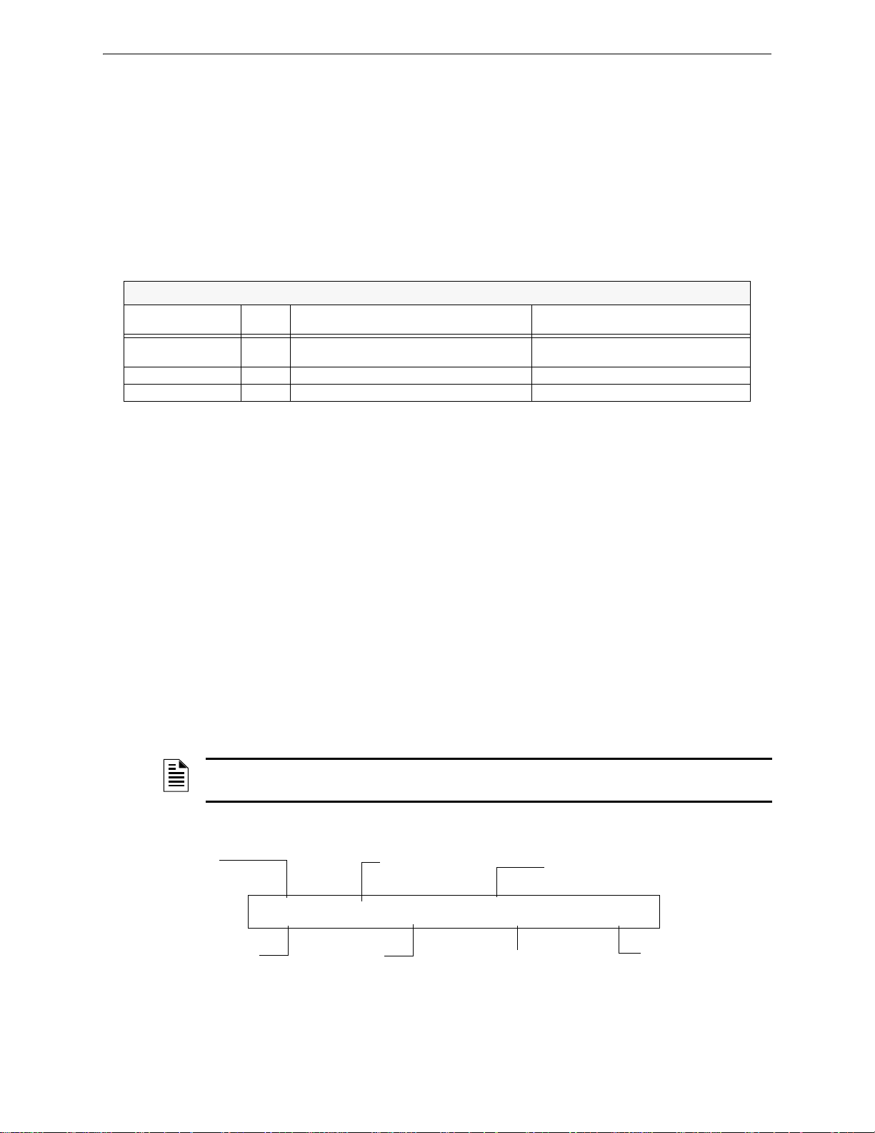
Operation of the Control Panel Active Supervisory Signal Mode of Operation
ACTIVE TAMPER INTENSIVE CARE UNIT
EASTERN WING Z004 03:19P 041511 2M147
Status Banner
Type Code
Custom descriptor for
this device location
Device address
Time and date of trouble
Zone
Extended 12 character
custom label
3. When you finish correcting the Security condition, press the SYSTEM RESET key to return the
control panel to normal operation (indicated by the “System Normal” message). The control
panel sends a “System Normal” message to the LCD display, History buffer and installed
printers, FDU-80 annunciators, and CRT-2s.
3.6.3 Interpreting Security Type Codes
The Type Code that displays in the security alarm message indicates the type of security alarm
being generated by the monitor module that initiates the alarm. For example, a monitor module
with a Type Code of
below lists the Type Codes that can appear in a security alarm message.
Type Code
AREA MONITOR Y Monitors area surveillance equipment, such
SECURITY Y Monitors security switches for tampering Lights SECURITY LED, activates CBE
SYS MONITOR Y Monitors critical equipment for security Lights SECURITY LED, activates CBE
Latching
(Y/N)
AREA MONITOR indicates an intruder in a protected premises area. The table
Monitor Modules
Purpose What it does
Lights SECURITY LED, activates CBE
as motion detectors
Table 3.3 Security Type Codes
3.7 Active Supervisory Signal Mode of Operation
3.7.1 How the Control Panel Indicates an Active Supervisory
The system goes into Supervisory mode when a monitor module point programmed with a
Supervisory type code activates. When a Supervisory point activates, the control panel does the
following:
• Produces a warbling audible tone
• Turns on the Supervisory relay (TB5)
• Flashes the SUPERVISORY LED (yellow)
• Displays one of the Type Codes listed in Table 3.4.
•Displays ACTIVE in the status banner on the control panel, along with information specific to
the device
• Sends a Supervisory message to the LCD display, History buffer, and installed printers,
FDU-80G annunciators, and CRT-2s
NOTE: If a fire alarm exists, and there are silenced alarms (the SIGNALS SILENCED LED is
lighted), a Supervisory alarm will resound the panel sounder.
A Typical Supervisory message that appears on LCD display:
24 NFS-320/E/C, NFS-320SYS/E Operations Manual — P/N 52747:E1 06/16/2011
Figure 3.10 Sample Supervisory Signal Message
Page 25

Active Supervisory Signal Mode of Operation Operation of the Control Panel
3.7.2 How to Respond to an Active Supervisory
If a Latching Supervisory Type Code Displays
Some Supervisory Type Codes latch the control panel (Refer to Table 3.4 for a list of these type
codes). To return the control panel to normal operation, you must correct the condition causing the
supervisory condition, then reset the control panel. Take the following action:
NOTE: If a fire alarm exists, and there are silenced alarms (the SIGNALS SILENCED LED is
lighted), a Supervisory alarm will resound the panel sounder.
1. Press the ACKNOWLEDGE/SCROLL DISPLAY key to silence the panel sounder and switch the
SUPERVISORY LED from flashing to steady—regardless of the number of troubles, alarms, and
supervisory signals. The control panel sends a Supervisory message to the History buffer and
installed printers, FDU-80 annunciators, and CRT-2s.
2. Correct the condition that activated the supervisory point.
3. When you finish correcting the latching supervisory condition, press the
return the control panel to normal operation (indicated by the “System Normal” message). The
control panel sends a “System Normal” message to the LCD display, History buffer and
installed printers, FDU-80 annunciators, and CRT-2s.
If Non-latching Type Code Displays
SYSTEM RESET key to
Some Supervisory Type Codes do not latch the control panel. (Refer to Table 3.4 for a list of these
type codes). The control panel automatically returns to normal operation, when you correct the
condition that activates the supervisory point. If the control panel indicates a non-latching
supervisory point, take the following action:
NOTE: If a fire alarm exists, and there are silenced alarms (the SIGNALS SILENCED LED is
lighted), a Supervisory alarm will resound the panel sounder.
1. Press the ACKNOWLEDGE/SCROLL DISPLAY key to silence the panel sounder and switch the
SUPERVISORY LED from flashing to steady—regardless of the number of troubles, alarms, and
supervisory signals. The control panel sends a Supervisory message to the History buffer and
installed printers, FDU-80 annunciators, and CRT-2s.
2. Correct the condition that activated the supervisory point.
3. The control panel automatically returns to normal operation (indicated by the “System
Normal” message) and the control panel sends a “System Normal” message to the LCD
display, History buffer and installed printers, FDU-80 annunciators, and CRT-2s.
3.7.3 How to Interpret Supervisory Type Codes
The Type Code that displays in the Supervisory message indicates the function of the point that
initiates the Supervisory. For example, a monitor module with a
monitor module connects to a tamper switch.
TAMPER Type Code means that the
NFS-320/E/C, NFS-320SYS/E Operations Manual — P/N 52747:E1 06/16/2011 25
Page 26

Operation of the Control Panel Pre-Alarm Warning Mode of Operation
Type Codes that can appear in an Supervisory message:
Monitor Modules
Type Code
WATERFLOW S Y Indicates supervisory condition for activated water flow switch Lights SUPERVISORY LED and activates CBE
RF SUPERVSRY N Monitors a radio frequency device Lights SUPERVISORY LED and activates CBE
LATCH SUPERV Y Indicates latching supervisory condition Lights SUPERVISORY LED and activates CBE
TRACK SUPERV N Indicates tracking supervisory condition Lights SUPERVISORY LED and activates CBE
SPRINKLR SYS Y Indicates activation of sprinkler system Lights SUPERVISORY LED and activates CBE
TAMPER Y Indicates activation of tamper switch Lights SUPERVISORY LED and activates CBE
Latching
(Y/N)
Purpose What it does
Detectors
SUP.T(DUCTI) N Ion detector that indicates supervisory (non-alarm) condition Lights SUPERVISORY LED and activates CBE
SUP.L(DUCTI) Y Ion detector that indicates supervisory (non-alarm) condition Lights SUPERVISORY LED and activates CBE
SUPT(DUCTL) N Laser detector that indicates supervisory (non-alarm) condition Lights SUPERVISORY LED and activates CBE
SUPL(DUCTL) Y Laser detector that indicates supervisory (non-alarm) condition Lights SUPERVISORY LED and activates CBE
SUP.T(DUCTP) N Photo detector that indicates supervisory (non-alarm) condition Lights SUPERVISORY LED and activates CBE
SUP.L(DUCTP) Y Photo detector that indicates supervisory (non-alarm) condition Lights SUPERVISORY LED and activates CBE
SUPT(PHOTO) N Photo detector that indicates supervisory (non-alarm) condition Lights SUPERVISORY LED and activates CBE
SUP.L(PHOTO) Y Photo detector that indicates supervisory (non-alarm) condition Lights SUPERVISORY LED and activates CBE
SUP.T(ION) N Ion detector that indicates supervisory (non-alarm) condition Lights SUPERVISORY LED and activates CBE
SUP.L(ION) Y Ion detector that indicates supervisory (non-alarm) condition Lights SUPERVISORY LED and activates CBE
SUP.L(LASER) Y Laser detector that indicates supervisory (non-alarm) condition Lights SUPERVISORY LED and activates CBE
SUP.T(LASER)
PHOTO/CO (C SUP)* Y Indicates activation of the Photo, Heat or CO element of a
PHOTO/CO (P SUP)* Y Indicates activation of the Photo, Heat or CO element of a
*FlashScan mode only
N
Laser detector that indicates supervisory (non-alarm) condition Lights SUPERVISORY LED and activates CBE
Activation of a Heat or Photo elements will
detector.
detector.
light an indicator at the control panel.
Activation of the CO element will light the
SUPERVISORY LED. Activates the CBE
Activation of a Heat element will light an
indicator at the control panel.
Activation of a CO alarm will not light an
indicator at the control panel.
Activation of the Photo element will light the
SUPERVISORY LED. Activates the CBE
Table 3.4 Supervisory Type Codes
3.8 Pre-Alarm Warning Mode of Operation
3.8.1 How the Control Panel Indicates a Pre-Alarm Warning
The control panel activates a Pre-Alarm Warning if a detector exceeds the programmed Pre-Alarm
Alert or Action level. When a detector activates a Pre-Alarm, the control panel does the following:
• Pulses the panel sounder
• Flashes the PRE-ALARM LED
• Activates the Pre-Alarm zone (F9)
• Sends a Pre-Alarm message to the LCD display, History buffer and installed printers, FDU-80
annunciators, and CRT-2s
• Displays a pre alarm status banner, the Type Code of the detector, and the Pre-Alarm level
(Alert or Action) on the LCD display, along with information specific to the device as shown
in
Figure 3.11.
26 NFS-320/E/C, NFS-320SYS/E Operations Manual — P/N 52747:E1 06/16/2011
Page 27
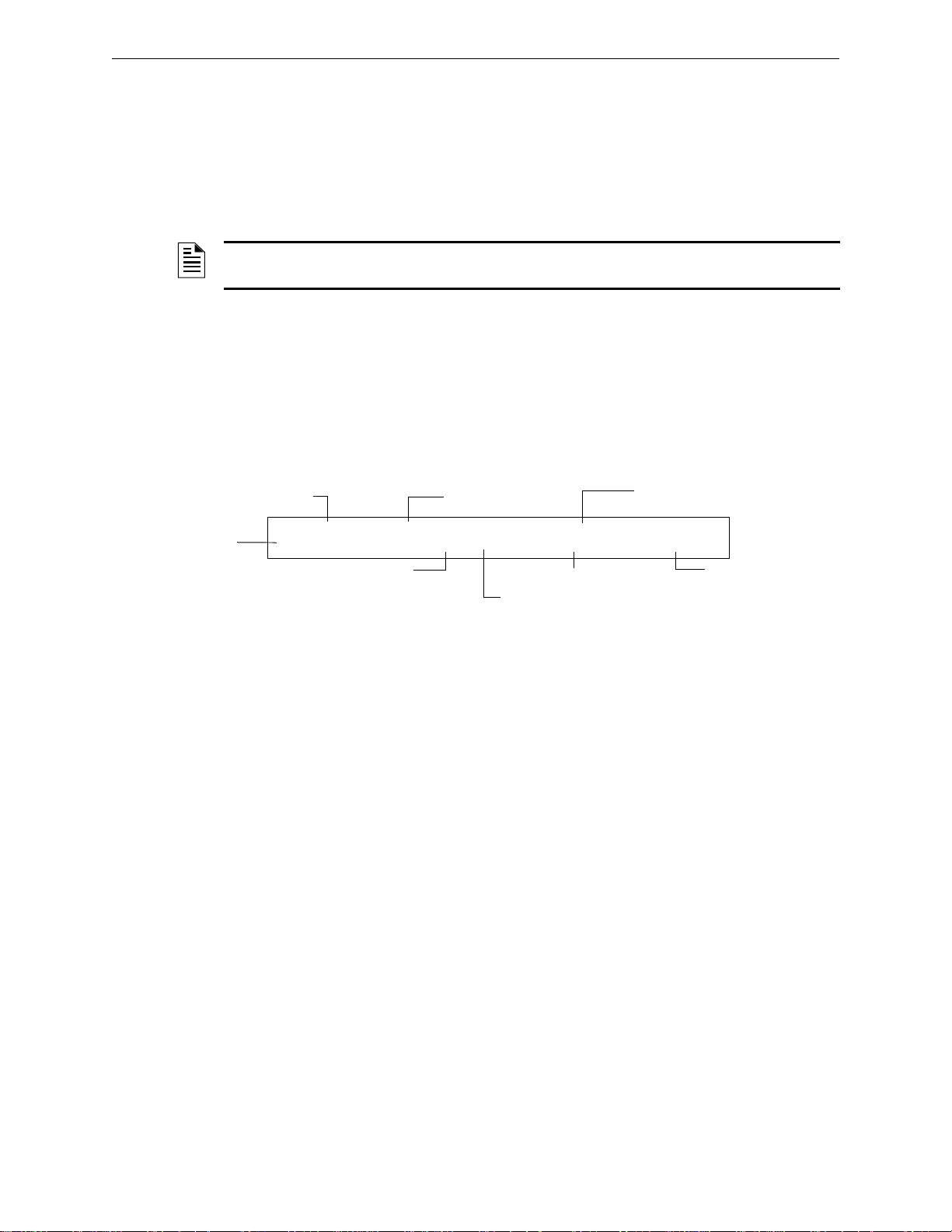
Pre-Alarm Warning Mode of Operation Operation of the Control Panel
Detector programmed for a Pre-Alarm level of 4
Shows the detector has reached 55% of the
programmed Pre-Alarm level. The 55% is a
real-time display and tracks smoke levels
Status banner
Type Code
PREALM SMOKE(PHOTO) INTENSIVE CARE UNIT
EASTERN WING 055%/4 03:20P 011511 1D147
Custom descriptor for
this device location
Device address
Time and date of trouble
Extended 12
character
custom label
3.8.2 How to Respond to a Pre-Alarm Warning
Pre-Alarm Alert and Action Levels
The Pre-Alarm function is a programmable option which determines the system’s response to realtime detector sensing values above the programmed setting. Use the Pre-Alarm function if you
want to get an early warning of incipient or potential fire conditions. The Pre-Alarm function
provides one of two levels of Pre-Alarm as follows:
NOTE: For detailed information on Pre-Alarm applications, refer to the NFS-320 Programming
Manual.
• Alert – a non-latching condition that causes a Pre-Alarm when a detector reaches the
programmed Pre-Alarm level.
• Action – a latching condition that causes a Pre-Alarm when a detector reaches the programmed
Pre-Alarm level.
Responding to a Pre-Alarm Warning
The Pre-Alarm screen display is the same for both alert and action conditions. Following is a
sample screen for a Pre-Alarm message.
Figure 3.11 Sample of an Alert Pre-Alarm Message
An Alert Pre-Alarm automatically restores to normal when the detector sensitivity, programmable
to one of nine settings, drops below the programmed Alert level. Zone F09 automatically clears
when no Pre-Alarm conditions exist.
An Action Pre-Alarm latches until you reset the system - even if the detector sensitivity drops
below the Action level. Zone F09 activates - but Zone Z00 (general alarm) and the trouble and
alarm relays do not activate. The fifth zone programmed, not the first four, in the detector’s CBE
activates. A subsequent alarm condition for this detector clears the Action indication from the LCD
display.
Interpreting Pre-Alarm Type Codes
The Type Code that displays in the Pre-Alarm warning indicates the function of the point that
initiates the Pre-Alarm warning. Refer to the Detectors section of
can appear in a Pre-Alarm warning, and for descriptions of those Type Codes.
Table 3.1 for the Type Codes that
NFS-320/E/C, NFS-320SYS/E Operations Manual — P/N 52747:E1 06/16/2011 27
Page 28
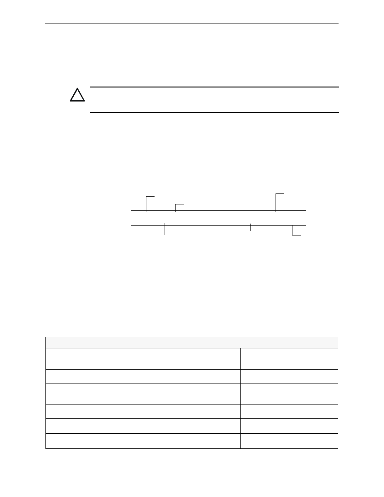
Operation of the Control Panel Disabled Points Mode of Operation
!
Disable message
Type Code of the disabled device
Address of the
disabled device
DISABL TAMPER INTENSIVE CARE UNIT
EASTERN WING 03:20P 011511 1M159
Custom descriptor for
this device location
Time and date of trouble
Extended 12 character
custom label
3.9 Disabled Points Mode of Operation
The control panel indicates disabled points by displaying a screen for each disabled detector,
monitor module, and control/relay module. Disabled points do not cause an alarm or any
Control-by-Event activity. If more than one point is disabled, the control panel automatically
displays by priority, mimicking the alarms.
CAUTION:
Disabling a zone disables all input and output devices associated with the zone if the zone is
in first zone “primary” mapped location.
When one or more points are disabled, the control panel does the following:
• Holds all disabled output points in the off-state
• Flashes the SYSTEM TROUBLE LED
•Lights the POINT DISABLED LED
• Sends a Disabled Point message to the LCD display, History buffer and installed printers,
FDU-80 annunciators, and CRT-2s
• Displays a message for each disabled point
3.10 Non-Alarm Mode of Operation
ACCESS MONTR N Used for monitoring building access Activates CBE
ACK SWITCH N Performs Acknowledge function Silences panel sounder, gives an
DRILL SWITCH N Performs Drill function Activates silenceable outputs
FIRE CONTROL N Used for air handler shutdown, intended to override
NON-FIRE N Used for energy management or other non-fire
PAS INHIBIT N Inhibits Positive Alarm Sequence Inhibits Positive Alarm Sequence
RESET SWITCH N Performs Reset function Resets control panel
SIL SWITCH N Performs Signal Silence function Turns off all activated silenceable outputs
ABORT SWITCH N Indicates Active at the panel Aborts activation of a releasing zone
28 NFS-320/E/C, NFS-320SYS/E Operations Manual — P/N 52747:E1 06/16/2011
Figure 3.12 Sample Disabled Point Message
3.10.1 Purpose of Non-Alarm Points
Non-Alarm points are addressable monitor modules programmed with one of the Non-Alarm Type
Codes listed in
Table 3.5. Non-Alarm points, except Non-Fire, operate like monitored system
functions that can produce troubles—but with the differences shown in the following sections.
Monitor Modules
Type Code
Latching
(Y/N)
normal operating automatic functions
situations. Does not affect operation of the control panel
Table 3.5 Non-Alarm Type Codes
Purpose What it does
Acknowledge message on the panel LCD
Activates CBE, does NOT light an
indicator at the control panel
Activates CBE, does NOT light an
indicator at the control panel
Page 29
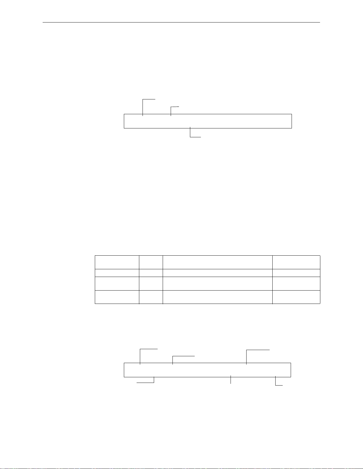
Active Trouble Monitor Mode of Operation Operation of the Control Panel
Status banner
Type Code
Zone affected by the Fire Control
ACTIVE FIRE CONTROL INTENSIVE CARE UNIT
EASTERN WING Z055 08:59a 011511 1M044
Status banner
Type Code
TROUBL TROUBLE_MON INTENSIVE CARE UNIT
EASTERN WING 09:38A 011511 1M044
Custom descriptor for
this device location
Device address
Time and date of trouble
Extended 12 character
custom label
3.10.2 How the Control Panel Indicates an Active Fire Control
Activation of a FIRE CONTROL point causes the control panel to do the following:
• Initiate the monitor module Control-by-Event
• Send a message to the LCD display, History buffer and installed printers, FDU-80
annunciators, and CRT-2s
• Display an ACTIVE status banner and FIRE CONTROL Type Code on the LCD display, along with
information specific to the device
Figure 3.13 Sample Fire Control Point Display
3.10.3 How the Control Panel Indicates an Active Non-Fire Point
Non-Fire point operation does not affect control panel operation, nor does it display a message at
the panel LCD. Activation of a Non-Fire point activates CBE—but does not cause any indication
on the control panel. For example, you can program a Non-Fire point to turn lights in a zone to a
lower setting when activated. In this case, when the point activates the control panel activates the
point’s CBE to turn the lights down without any audio or visual indication on the control panel.
3.11 Active Trouble Monitor Mode of Operation
3.11.1 How the Control Panel Indicates an Active Trouble Monitor
Trouble Monitor Points are monitor modules programmed with the following Type Codes:
Type Code
EQUIP MONITR N Used for recording access to monitored equipment Activates CBE
POWER MONITR N Used to monitor remote power supplies or other
TROUBLE MON N Used to monitor remote power supplies or other
These types of monitor modules operate like monitored system functions that can produce
troubles—but with the following differences:
• The LCD display status banner displays ACTIVE as shown:
Latching
(Y/N)
external equipment
external equipment
Device Function Point Function
Table 3.6 Trouble Monitor Type Codes
Indicates trouble
Indicates trouble
NFS-320/E/C, NFS-320SYS/E Operations Manual — P/N 52747:E1 06/16/2011 29
Figure 4 Sample Trouble Monitor Point Message
• The monitor module is non-latching: the module will return to normal when the trouble
condition no longer exists.
• The monitor modules activate Control-by-Event
Page 30

Operation of the Control Panel Output Circuit Trouble Mode of Operation
• The panel trouble relay transfers (TB4)
3.11.2 How to Respond to an Active Trouble Monitor
If the control panel indicates an active Trouble Monitor Point, take the following action:
1. Press the ACKNOWLEDGE/SCROLL DISPLAY key to silence the panel sounder and switch the
SYSTEM TROUBLE LED from flashing to steady—regardless of the number of troubles, alarms,
and supervisory signals.
2. The control panel sends an Acknowledge message to the History buffer and installed printers,
FDU-80 annunciators, and CRT-2s. Check the trouble message for the location an d type of
trouble.
3. Correct the condition causing the trouble.
4. When the trouble condition is corrected, the panel will return to normal operation (indicated by
the “System Normal” message).
5. The control panel sends a “System Normal” message to the LCD display, History buffer and
installed printers, FDU-80 annunciators, and CRT-2s.
3.12 Output Circuit Trouble Mode of Operation
3.12.1 Overview
Output circuits include NACs, Control/Relay Modules, and Transponder Points. This section
contains a description of control panel operation for each type of output circuit.
• Four NACs are included on the control panel
• Control/Relay Modules connected to the control panel on an SLC
• Transponder Points: XPC-8 (CLIP only), or XP6-C (CLIP or FlashScan)
Trouble Type Codes for Control Modules and NAC Circuits
Type Code
CONTROL N NAC Supervised NAC
RELAY N FORM-C relay Relay Output
BELL CIRCUIT N NAC Supervised NAC for notification appliance
STROBE CKT N NAC Supervised NAC for notification appliance
HORN CIRCUIT N NAC Supervised NAC for notification appliance
AUDIBLE CKT N NAC Supervised NAC for notification appliance
REL END BELL N NAC Supervised NAC for notification appliance
blank N NAC Supervised NAC for undefined device
RELEASE CKT N NAC Directs outputs to perform a releasing function.
REL CKT ULC N NAC Directs outputs to perform a release function as required by ULC.
REL AUDIBLE N NAC NAC, activated upon release
NONRESET CTL* N NAC Relay output, unaffected by “System Reset” command
TELEPHONE N NAC Standard Telephone circuit
REL CODE BELL** N NAC Supervised NAC (NFS-320 NAC only)
INSTANT RELE N NAC NAC, short = normal; supervised for open circuits and ground
ALARMS PEND N NAC Output that will activate upon receipt of an alarm condition, and
CONTROL NAC** N NAC Supervised NAC
Silenceable
(Y/N)
Configuration Device Function
faults. Always non-silenceable and switch-inhibited.
remain in the alarm state until all alarms have been
acknowledged.
Table 3.7 Control Module and NAC Circuit Trouble Type Codes (1 of 2)
30 NFS-320/E/C, NFS-320SYS/E Operations Manual — P/N 52747:E1 06/16/2011
Page 31
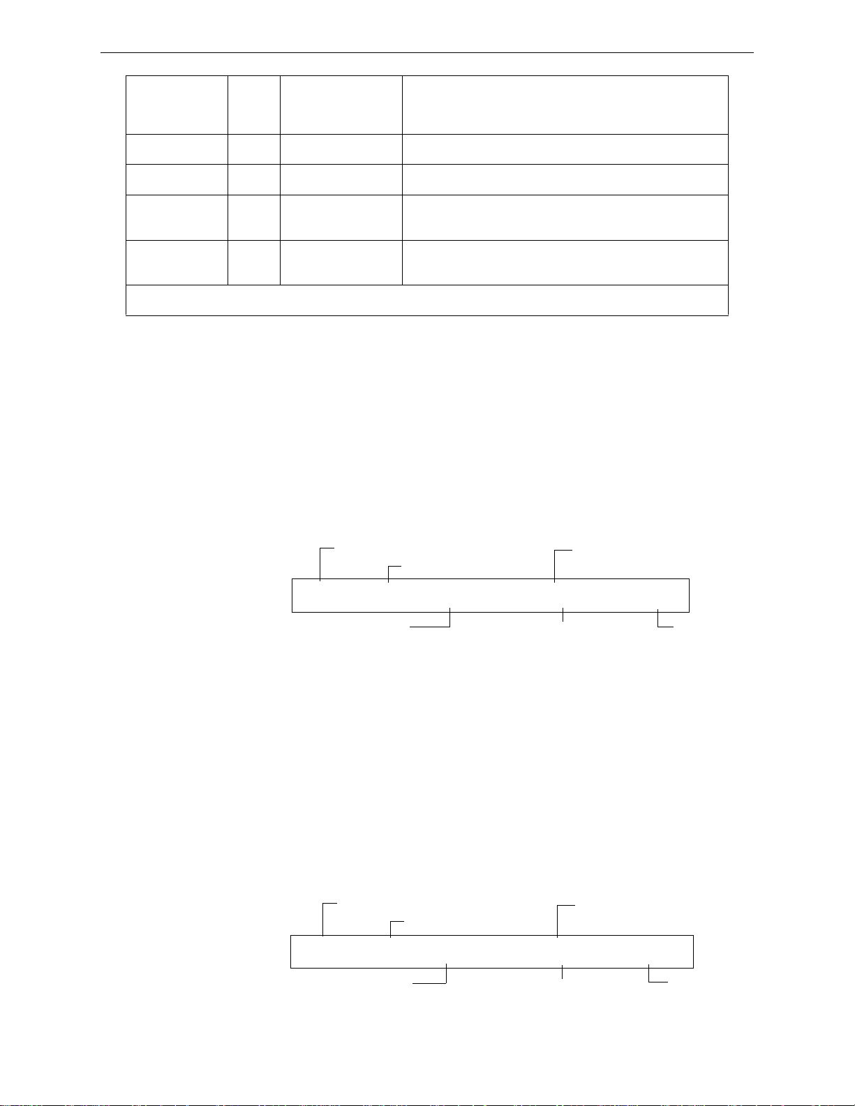
Output Circuit Trouble Mode of Operation Operation of the Control Panel
Status banner
Type Code
Time and date of trouble
TROUBL CONTROL FRONT HALLWAY NO. 2
OPEN 09:38A 011511 B02
Device Address
Type of Trouble
Custom Description for
this device location
TROUBL CONTROL MODULE ADDR 1M044
OPEN 09:38A 011511 1M044
Status banner
Type Code
Time and date of trouble
Device Address
Type of Trouble
Custom Description for
this device location
GEN ALARM Y Control Module, an XPC-8 circuit, or an XP6-C configured as a
Municipal Box Transmitter for NFPA 72 Auxiliar y Fire Alarm
Systems application. This Type ID can also be used for general
alarm activation.
GEN SUPERVIS Y Control Module, an XPR-8 relay, or an XP6-R activated under
any Supervisory condition (includes sprinkler type).
GEN TROUBLE Y Control Module, an XPR-8 relay, or an XP6-R activated under
GENERAL PEND Y Control Module, an XPC-8 circuit, or an XP6-C that will activate
TROUBLE PEND N Control Module, an XPC-8 circuit, or an XP6-C that will activate
* Type Code is Control Module type code only.
** Type Code is NAC Circuit type code only.
any System Trouble condition.
upon receipt of an alarm and/or trouble condition, and remain in
the ON state until all events have been ACKNOWLEDGED.
upon receipt of a trouble condition, and remain in the ON state
until all troubles have been ACKNOWLEDGED.
Table 3.7 Control Module and NAC Circuit Trouble Type Codes (2 of 2)
3.12.2 How the Control Panel Indicates a NAC Trouble
A Trouble occurring on a NAC causes the control panel to do the following:
• Produce a pulsed audible tone
• Flash the SYSTEM TROUBLE LED
• Turn on the Trouble relay (TB4)
• Send a message to the LCD display, History buffer and installed printers, FDU-80
annunciators, and CRT-2s
• Display a trouble status banner and a CONTROL Type Code on the LCD display, along with
information specific to the device
Figure 3.1 Sample of a NAC in Trouble Message
3.12.3 How the Control Panel Indicates a Control/Relay Trouble
A trouble occurring on a control/relay module or control/relay transponder causes the control panel
to do the following:
• Produce a pulsed audible tone
• Flash the SYSTEM TROUBLE LED
• Turn on the Trouble relay (TB4)
• Send a message to the LCD display, History buffer and installed printers, FDU-80
annunciators, and CRT-2s
• Display a trouble status banner and CONTROL Type Code on the LCD di splay, along with
information specific to the device
NFS-320/E/C, NFS-320SYS/E Operations Manual — P/N 52747:E1 06/16/2011 31
Figure 3.2 Sample of a Control/Relay Module in Trouble Message
Page 32
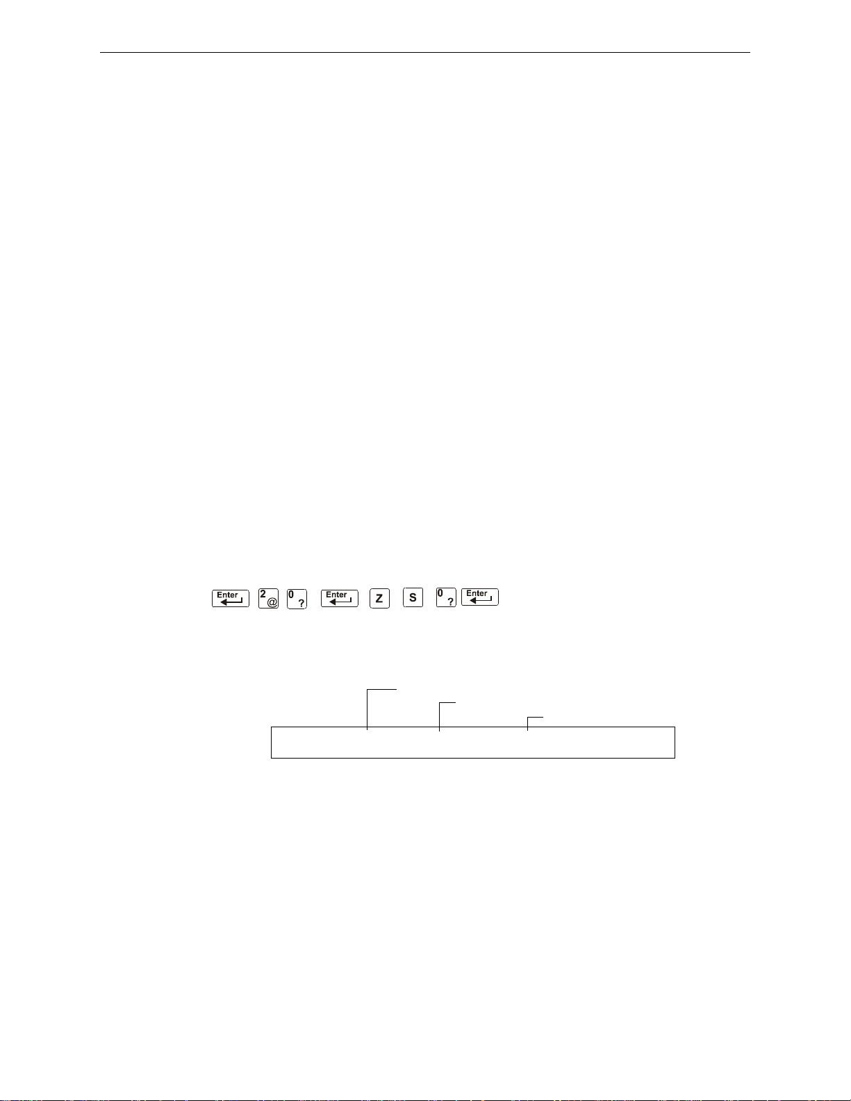
Operation of the Control Panel Operation of Special System Timers
Silence Inhibit Timer set to 180 seconds
Auto Silence Timer set to 600 seconds
Alarm Verification Timer set to 30 seconds
SIL INH=180 AUTO=600 VERIFY=30 USA TIME
TERM=N AC-DLY=Y LocT BLINK=01 ST=4 ACS=N
3.12.4 How to Respond to a NAC or Control/Relay Trouble
If the control panel indicates an active NAC or Control/Relay Trouble, take the following action:
1. Press the ACKNOWLEDGE/SCROLL DISPLAY key to silence the panel sounder and switch the
SYSTEM TROUBLE LED from flashing to steady—regardless of the number of troubles, alarms,
and supervisory signals.
2. The control panel sends an Acknowledge message to the History buffer and installed printers,
FDU-80 annunciators, and CRT-2s. Check the trouble message for the location an d type of
trouble.
3. Correct the condition causing the trouble.
4. When the trouble condition is corrected, the panel will return to normal operation (indicated by
the “System Normal” message).
5. The control panel sends a “System Normal” message to the LCD display, History buffer and
installed printers, FDU-80 annunciators, and CRT-2s.
3.13 Operation of Special System Timers
3.13.1 What are System Timers?
There are user-programmable time delays for three specific functions: the Auto Silence Timer, the
Alarm Verification Timer, and the Silence Inhibit Timer.
Function Selection screen with system timer settings. For instructions on changing system
functions, refer to the NFS-320 Programming Manual.
Figure 3.3 shows a sample System
3.13.2 How to View System Timer Selections
You can use the Read Status Entry option (explained in Chapter 4) to view the current selection for
the System Timers. To do so, press the keys shown below in sequence:
The LCD display shows the current selections for System Functions, which includes the three
system timers.
Sample LCD display of a System Function screen with system timer selections:
Figure 3.3 Sample System Function Selection Screen
3.13.3 How System Timers Work
The control panel can operate with special system timers: Auto Silence Timer, Alarm Verification
Timer and Silence Inhibit Timer.
Auto Silence Timer
A timer that functions like pressing the SIGNAL SILENCE key. When the Auto Silence Timer reaches
its programmed value (600-900 seconds), the control panel automatically shuts off all active
outputs programmed as silenceable.
32 NFS-320/E/C, NFS-320SYS/E Operations Manual — P/N 52747:E1 06/16/2011
Page 33

Waterflow Circuit Operation Operation of the Control Panel
Alarm Verification Timer
A timer that directs the control panel to ignore a fire alarm for a smoke detector, programmed for
Alarm Verification, while the Alarm Verification Tim e r is counting.
Table 3.8 contains a summary
of how the Alarm Verification Timer works.
If The control panel does this
A second fire alarm occurs while the
Alarm Verification Timer is counting
The Alarm Verification Timer elapses and
a fire alarm still exists
The Alarm Verification T imer expires and
a fire alarm no longer exists
Ignores the Alarm Verification Timer
Activates the fire alarm
Increments the Alarm Verification counter (up to 99)
for the device and returns to normal operation
Table 3.8 Alarm Ve rification Timer Operation
Silence Inhibit Timer
A timer that disables the SIGNAL SILENCE key function and inhibits reset during countdown for the
programmed time (0-300 seconds) when a fire alarm occurs. A Silence Inhibit Timer starts at the
first fire alarm. Subsequent alarms will not restart the timer until the alarm condition is completely
resolved and a panel reset is performed.
3.14 Waterflow Circuit Operation
If a monitor module programmed with a WATERFLOW Type Code initiates a fire alarm, the control
panel disables the
SIGNAL SILENCE key and the Auto Silence Timer. Refer to the NFS-320
Installation Manual for information on Waterflow circuits.
3.15 Style 6 and Style 7 Operation
Style 6 and Style 7 are supervised methods of communicating with addressable devices. If the
control panel detects a trouble (open or short), it will attempt to drive both ends of the loop,
maintaining communication in an unsupervised method. The trouble will display on the panel as a
Style 6 trouble until you correct the condition. Style 7 configuration of the SLC requires the use of
ISO-X isolator modules.
NFS-320/E/C, NFS-320SYS/E Operations Manual — P/N 52747:E1 06/16/2011 33
Page 34
Section 4: Read Status Operation
1=PROGRAMMING 2=READ STATUS ENTRY
(ESCAPE TO ABORT)
READ POINT=0 HIST=2 ALARM HIST=4 <ENTER>
PRNT POINT=1 HIST=3 ALARM HIST=5 <ENTER>
4.1 Introduction
This section contains instructions and sample screens to show how to access all Read Status
functions and menus. For information on Read Status using a CRT-2 refer to
“Remote Terminal Mode Functions”, on page 62.
4.2 What is Read Status?
Read Status is a control panel function that lets you view system program information—but not
change any programmed settings. The Read Status function lets you do the following:
• View Read Status information without entering a password.
• Enter and operate Read Status functions while the control panel provi des full fire protection.
• View Read Status information while a fire alarm or trouble condition exists.
NOTE: If a fire alarm or trouble occurs while you are in Read Status, the control panel
automatically exits Read Status operation and displays the new fire alarm or trouble.
4.2.1 Quick Reference Key Sequences
Appendix C.3,
For quick reference, in the left margin next to each Read Status option is a block that
shows the key sequence needed to view that option.
For example, the block to the left shows how to display the “Read Point” screen:
4.3 Entering Read Status
To enter Read Status, follow these steps:
1. From the “System Normal” screen, press the ENTER key. The control panel displays the
“Entry” screen as shown below;
2. From the “Entry” screen, press the 2 key. The control panel displays the “Read Status Options”
screen as shown below:.
34 NFS-320/E/C, NFS-320SYS/E Operations Manual — P/N 52747:E1 06/16/2011
Page 35
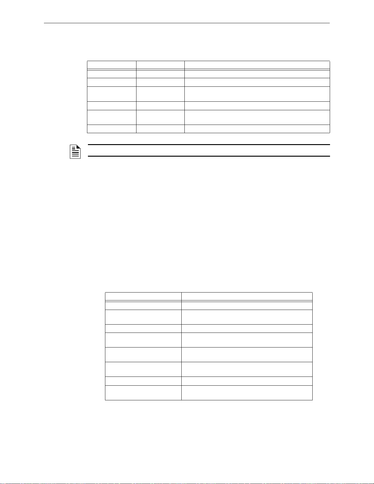
Viewing and Printing a Read Status Read Status Operation
4.4 Viewing and Printing a Read Status
To view or print Read Status information follow the instructions below:
Option Press Lets you
Read Point 0 key, ENTER key View information for a detector, module, NAC or zone
Print Points 1 key, ENTER key Print information for all installed points in the system
Read History 2 key, ENTER key Display the total number of events in the History buffer and step
through each event in sequence
Print History 3 key, ENTER key Print the contents of the History buffer (up to 800 events)
Read Alarm History 4 key, ENTER key View a display of the number of alarms in the Alarm History buffer ,
then scroll through each alarm event
Print Alarm History 5 key, ENTER key Print the contents of the Alarm History buffer (up to 200 events)
NOTE: If attempting to read a point that is not installed, the control panel displays “Not Installed”.
During all Read Status operations (except print operations) the control panel starts a 2-minute timer
each time you press a key . If the control panel does not de tect a key press for 2 minutes, the control
panel exits Read Status and returns to the “System Normal” display.
In Read Status, you can also do the following:
• Press the ESC key to delete the previous entry.
• Press the SYSTEM RESET key to abort Read Status.
4.4.1 How to View Read St atus of Devices, Zones, & System Settings
Overview
Read Point options 0, 2, and 4 in the Read Status Screen let you display and view information for
devices and zones programmed into the control panel, as well as view system and annunciator
settings. This section provides instructions and sample displays so you can view Read Status.
T opics covered in this section:
To view Read Status for Refer to
Intelligent Detectors “How to View Read Status for a Detector” on page 36
Control/relay and Monitor
modules
NAC “How to View Read Status for a NAC” on page 38
Software Zones (Z01-Z99) “How to View Read Status for a Software Zone (Z01-Z99)”
Special Zones (F0-F9) “How to View Read Status for a Special Zone (F0-F9)” on
Releasing Zones (R0-R9) “How to View Read Status for a Releasing Zone (R0-R9)”
System Functions “How to Read Status for System Functions” on page 40
Annunciator Selections “How to Read Status for Annunciator Selections” on
“How to View Read Status for a Control/Relay or Monitor
Module” on page 37
on page 39
page 39
on page 40
page 41
NFS-320/E/C, NFS-320SYS/E Operations Manual — P/N 52747:E1 06/16/2011 35
Page 36
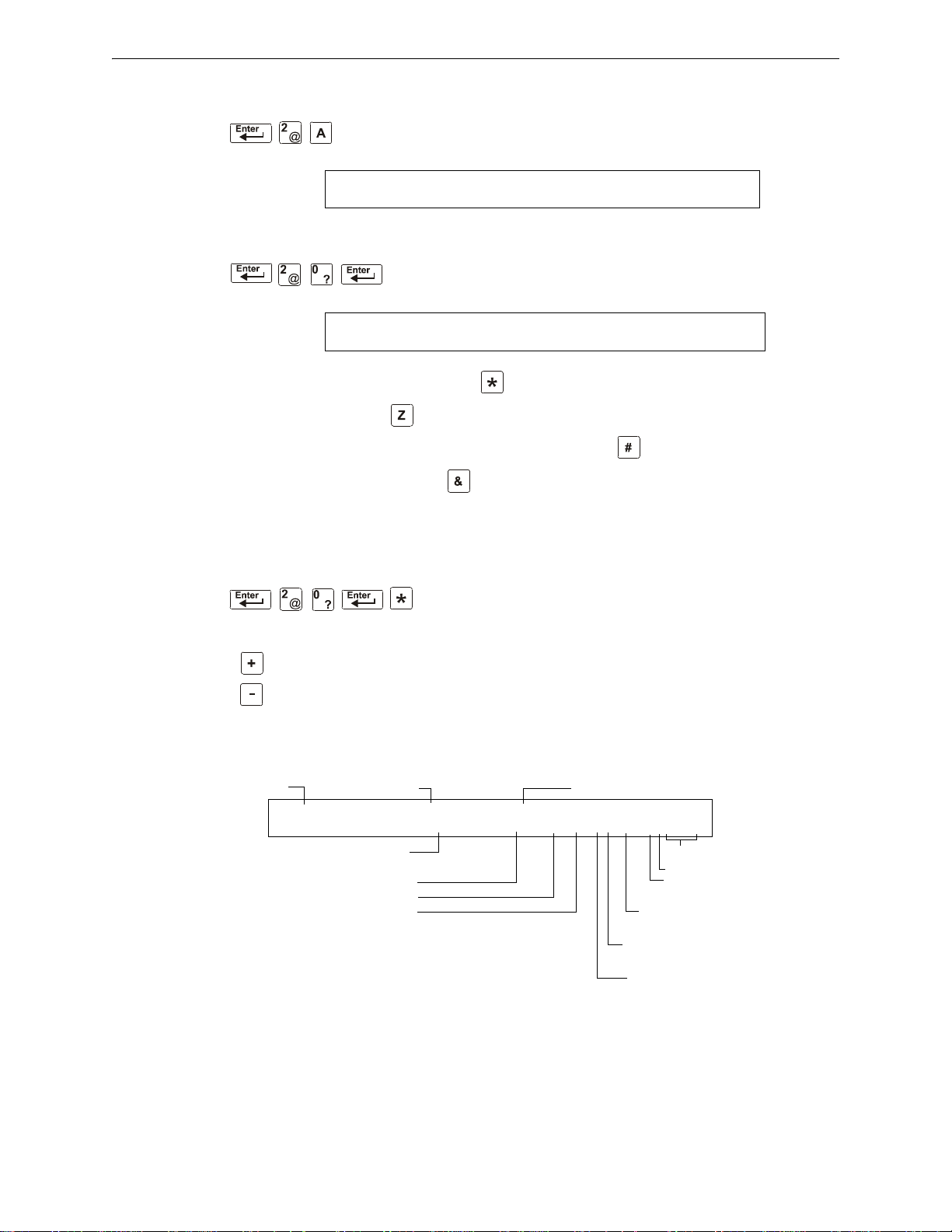
Read Status Operation Viewing and Printing a Read Status
L1:159Dets, 159Mods
SB L1:000: 64 Bells: 04
ZONE=Z,AA,E DETECTOR=*,LDAAA,E
MODULE=#,LMAA,E OUTPUT CKT=8,AA,E
Three digit address
next device
previous device
Type Code
Alarm Verification selection:
V on; * off
Multidetector selection:
A, B, C, or * (not selected)
Label for the detector
Current alarm reading (percent)
Alarm sensitivity level
Pre-Alarm sensitivity level
Device status
SLC Address (001-159)
D (detector)
SLC number (always 1)
NORMAL SMOKE (ION) INTENSIVE CARE UNIT
EASTERN WING Z002 001%A6 6 CV00 1D002
Default CBE zone selection
Alarm Verification Time
(in seconds)
How to Display the Total of Installed Devices
To view the total number of installed devices, enter the “Read Status” screen
by pressing the ENTER key, then 2, then A. A screen similar to the following
will appear:
How to Display a Point or Zone for Read Status
From the “Read Status” screen, press 0, then press the ENTER key to
display the “Read Point Entry” screen as shown below:
• To view a detector, press DETECTOR , detector SLC address, ENTER.
• To view a zone, press , zone number, ENTER.
• To view a monitor or control/relay module, press MODULE , module SLC address, ENTER.
• To view a NAC, press OUTPUT , two-digit address, (for example 01 for B01, etc.), ENTER.
When you select a device or a zone, the control panel displays information for the device or zone,
but does not send this information to the serial ports or the History buffer.
How to View Read Status for a Detector
From the “Read Status” screen, press 0, then press the ENTER
key. You can now view Read Status for a detector as follows:
press
DETECTOR, enter the three digit address, then press the
ENTER key. For example, to read the status of detector 1D002:
press
DETECTOR, enter address 002, then press the ENTER key.
The control panel now displays information about the detector,
as shown in
The display and descriptions of the fields are shown below:
Figure 4.1.
36 NFS-320/E/C, NFS-320SYS/E Operations Manual — P/N 52747:E1 06/16/2011
Figure 4.1 Sample Detector Read Status Display
Page 37
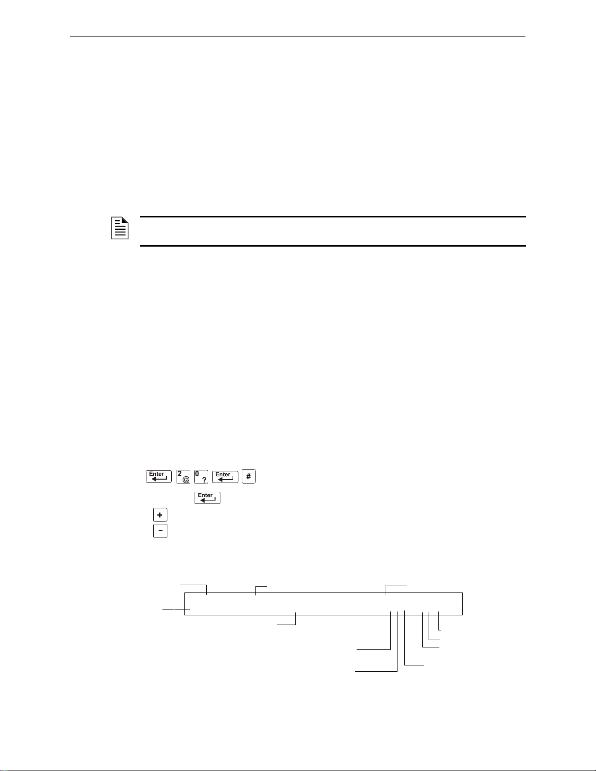
Viewing and Printing a Read Status Read Status Operation
SLC address
next device
previous device
Type Code (CONTROL)
Walk Test selection:
W selected for Walk Test
* not selected
Label for the module
Extended 12character
custom label
SLC Address (001-159)
M (module)
SLC number (always 1)
Switch Inhibit: I selected, * not selected
Device status
OFF CONTROL INTENSIVE CARE UNIT
DOORHOLDER#2 Z000 *O* 1M147
Default CBE zone selection
Silenceable: O = selected, * = not selected (default)
• Device Status The status of the detector: Normal, Alarm, or Test.
• Type Code The software Type Code that identifies the type of detector. (Refer to “Point
Programming” in the NFS-320 Programming Manual.)
• Default CBE Zone Selection This is the first zone in the 5 zone CBE list. Defaults are Zone
001 (Heat detectors) Zone 002 (Ion detectors) Zo ne 003 (Photo detectors) Zone 004 (Laser
detectors) Zone 005 (Multisensor). Values may differ depending on point programming.
• Current alarm reading (xxx%) The current alarm reading of the detector, as a percentage of
the alarm sensitivity setting.
• Alarm sensitivity level (Ax) The alarm sensitivity (x=1-9) entered in the Detector Sensitivity
Screen.
• Pre-Alarm sensitivity level The Pre-Alarm Sensitivity (1-9; 0 = Pre-Alarm not used) entered
in the Detector Settings Screen.
NOTE: Refer to “Detector Sensitivity Settings” in the NFS-320 Programming Manual for more
information on the Pre-Alarm and Alarm Sensitivity settings
• Cooperative Multi-Detector selection A smoke detector programmed to evaluate readings
from nearby detectors in making Alarm or Pre-Alarm decisions. Cooperative Multi-Detector
sensing also allows the combination of ionization with photoelectric technology in reaching an
alarm decision.
* – Multi-not used.
A – combines the detector’s alarm decision with the next SLC address above.
B – combines the detector’s alarm decision with the next SLC address below.
C – combines the detector’s alarm decision with the next SLC address above and the next SLC
address below.
• Alarm Verification (* or V)
* – Alarm Verification not programmed for this detector.
V – Alarm Verification enabled.
Alarm Verification is a user-defined global time function that can reduce the number of
nuisance alarms. Refer to page
page 33 for more information.
• Device SLC Address The SLC address of the detector.
NFS-320/E/C, NFS-320SYS/E Operations Manual — P/N 52747:E1 06/16/2011 37
How to View Read Status for a Control/Relay or Monitor Module
From the “Read Status” screen, press 0, then press the ENTER
key. You can now view Read Status for a monitor or a
control/relay module as follows: press
address, then press the
status of an FCM-1 module 1M147: press
then press the
information about the module as shown in
The display and descriptions of the fields are shown below:
Figure 4.2 Sample Control/Relay or Monitor Module Read Status Display
MODULE, enter the SLC
ENTER key. For example, to read the
MODULE, enter 147,
ENTER key. The control panel now displays
Figure 4.2.
Page 38
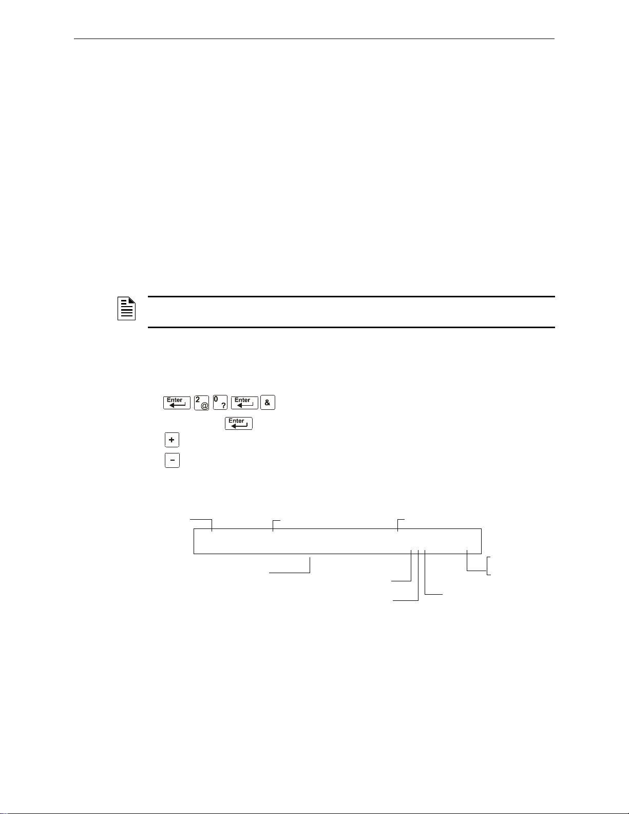
Read Status Operation Viewing and Printing a Read Status
Device address
next device
previous device
Type Code (CONTROL)
Walk Test selection:
W selected for Walk Test
* not selected
Label for the NAC
Default zone selection
Address (01-04)
B = NAC
Switch Inhibit: I selected, * not selected
Device status
Silenceable: O = selected, * = not selected (default)
OFF CONTROL FRONT HALLWAY NO. 2
Z000 *OW B02
• Device Status The status of the module: control/relay module [On (device active) OFF (device
not active] or monitor module (Normal, Alarm, or Test).
• Type Code The software Type Code that identifies the type of module. (Refer to “Point
Programming” in the NFS-320 Programming Manual.)
• CBE list Only the first zone in the device’s CBE list will be displayed.
• Device SLC Address The SLC address of the module.
• Switch Inhibit (control/relay module only) Displays whether the remote ON/OFF capability
of the device is inhibited. (I=on; *=off).
• Silenceable (control/relay module only) A selection that specifies if the device can be
silenced during an alarm by pressing the signal silence key. Possible values are:
* = output nonsilenceable
F = silenceable, resound by fire alarm
U = silenceable, resound by supervisory alarm
B = silenceable, resound by security alarm
T = silenceable, resound by trouble
O = silenceable, does not resound
NOTE: If the “Strobe” Type ID is used with System Sensor Strobe synchronization, F, U, B, T, or
O will silence the entire circuit, “*” will silence the horn portion only.
Walk Test (control/relay module only) A selection that specifies if the device will activate
during a Walk Test.
How to View Read Status for a NAC
From the “Read Status” screen, press 0, then press the ENTER
key. You can now view Read Status for a NAC as follows:
press
OUTPUT, enter the device address, then press the ENTER
key. For example, to read the status of NAC 0-2: press
OUTPUT, enter 02, then press the ENTER key. The control
panel now displays information for a NAC as shown in
Figure 4.3.
The display and descriptions of the fields are shown below:
Figure 4.3 Sample NAC Read Status Display
38 NFS-320/E/C, NFS-320SYS/E Operations Manual — P/N 52747:E1 06/16/2011
• Device Status The status of the device: ON (device active) OFF (device not active).
• Type Code The software Type Code that identifies the type of NAC. Refer to “Appendix F Type Codes” in the NFS-320 Programming Manual.
• CBE List Only the first zone in the NAC’s CBE list will be displayed here.
• Device Address The address of the NAC (01-04)
• Switch Inhibit A selection for disabling the switch function for the control/relay or
transponder output circuit. (I=on; *=off).
Page 39
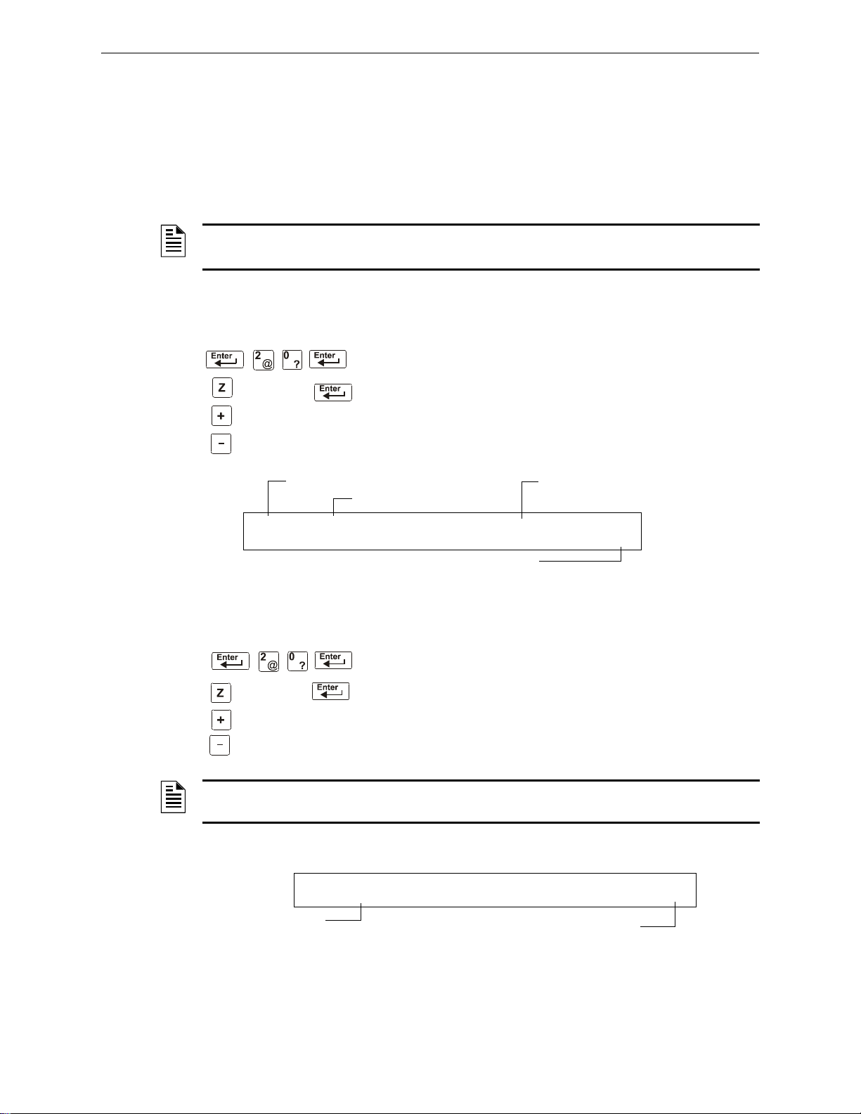
Viewing and Printing a Read Status Read Status Operation
Software
Zone Number
next device
previous device
Zone label for zones 01-99
Custom zone label for the zone
entered in during program Change
Zone Number
Zone status (ON or OFF)
OFF SOFTWARE ZONE 3RD FLOOR CAFETERIA
Z07
Special
Zone Number
next device
previous device
Zone label for Special Function F8
Indicates Special Zone F8
Zone status (ON or OFF)
Code Type selection
for Special Zone F8
OFF CODING FUNCTION CODE TYPE
MARCH TIME F8
• Silenceable A selection that specifies if the device can be silenced during an alarm by pressing
the
SIGNAL SILENCE key. Possible values are:
* = output nonsilenceable
F = silenceable, resound by fire alarm
U = silenceable, resound by supervisory alarm
B = silenceable, resound by security alarm
T = silenceable, resound by troubl
O = silenceable, does not resound
NOTE: If the “Strobe” Type ID is used with System Sensor Strobe synchronization, F, U, B, T,
or O will silence the entire circuit, “*” will silence the horn portion only.
• Walk Test A selection that specifies if the device will activate during a Walk Test.
How to View Read Status for a Software Zone (Z01-Z99)
From the “Read Status” screen, press 0, then press the ENTER
key. You can now view Read Status for a Software Zone as
follows: press Z, enter the zone number (01-99), then press the
ENTER key . For example, to read the status of Software Zone 07:
press Z, enter 07, then press the
now displays information for a Software Zone as shown below.
ENTER key. The control panel
Figure 4.4 Sample Software Zone Read Status Display
How to View Read Status for a Special Zone (F0-F9)
From the “Read Status” screen, press 0, then press the ENTER
key. You can now view Read Status for a Special Zone as
follows: press
ENTER key. For example, to read the status of Special Zone F8:
press
Z, enter F8, then press the ENTER key. The control panel
now displays information for a Special Zone as shown below
NOTE: The zone label depends on the type of Special Zone. For example, CODING FUNCTION
CODE TYPE for F8.
Figure 4.5 Sample Special Zone Read Status Display
Z, enter the zone number (F0-F9), then press the
.
NFS-320/E/C, NFS-320SYS/E Operations Manual — P/N 52747:E1 06/16/2011 39
Page 40
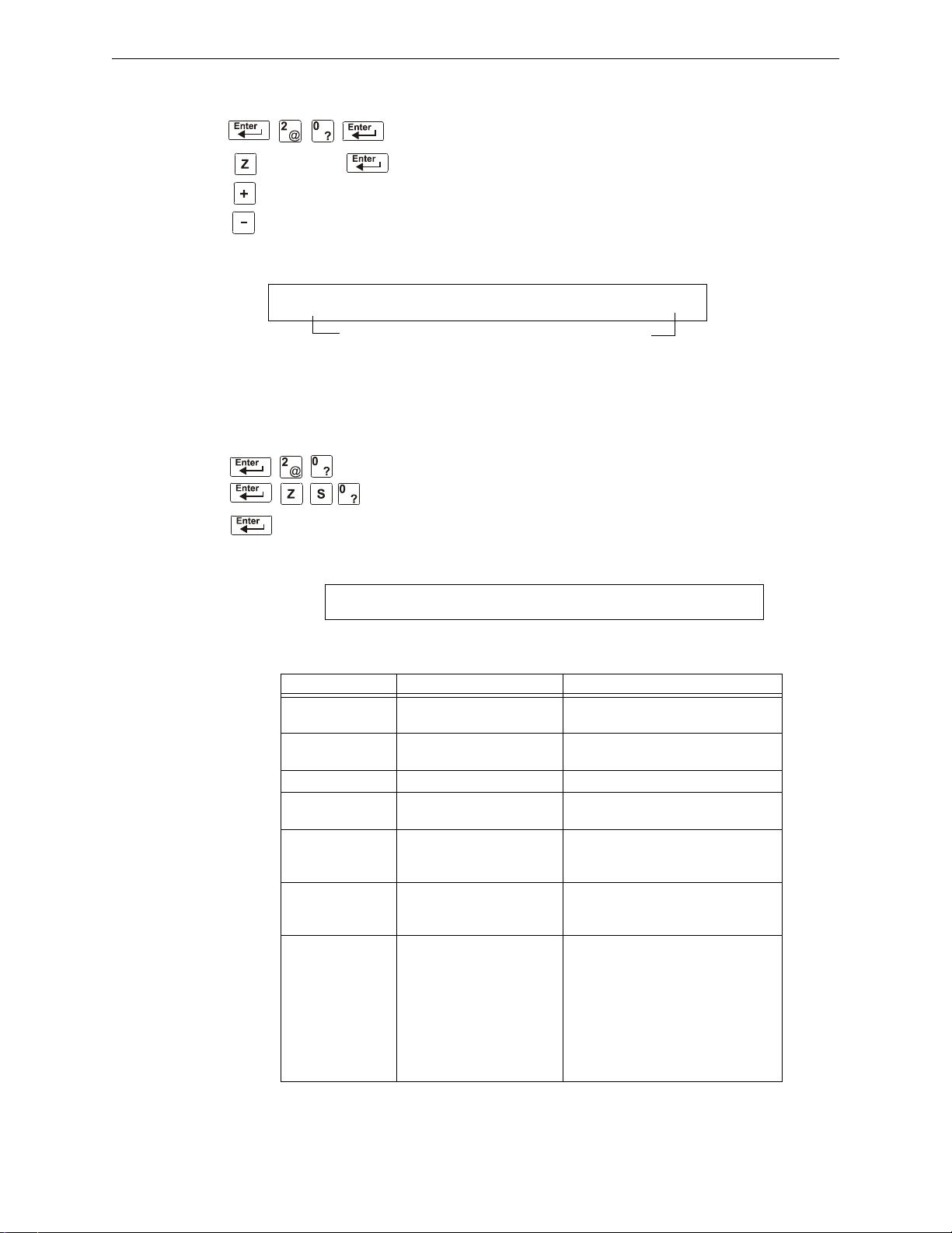
Read Status Operation Viewing and Printing a Read Status
Releasing
Zone Number
next device
previous device
Zone label for Releasing Function
Indicates Special Zone R0
Zone status (ON or OFF)
Selections for
Releasing Zone R0
OFF RELEASE FUNCT RELEASE CONTROL
DELAY=00 ABORT=ULI CROSS=N SOK=0000 R00
SIL INH=000 AUTO=000 VERIFY=30 USA TIME
TERM=N AC_DLY=Y LocT BLINK=01 ST=4 ACS=N
How to View Read Status for a Releasing Zone (R0-R9)
From the “Read Status” screen, press 0, then press the ENTER
key. You can now view the Read Status of a Releasing Zone as
follows: press Z, enter the zone number (R0-R9), then press the
ENTER key. For example, to read the status of Releasing Zone
R0, enter Z, enter R0, then press the
ENTER key. The control
panel now displays information for a Releasing Zone as shown
below.
Figure 4.6 Sample Releasing Zone Read Status Display
How to Read Status for System Functions
The “System Functions” screen specifies global settings for the
control panel. From the “Read Status” screen, press 0, then press the
ENTER key. You can now view Read Status for System Functions as
follows: press Z, enter S0, press the
sample display and description of items for the Read Status of System
Functions:
ENTER key. Shown below is a
Parameter Description Settings
SIL INH=000 Silence Inhibit timer in
seconds.
AUTO=000 Auto Silence Timer in
seconds.
VERIFY=30 Alarm Verification Timer 00 = no timer; 00-30 seconds.
USA TIME Time and date display
format
TERM=N Terminal supervision YES – To supervise the wiring of an
AC_DLY=N Delays AC loss reporting YES - AC loss reporting is delayed for
LocT One of three operating
modes of a PC or terminal
connected to the control
panel (through TB12 PC
Terminal)
000 = no timer; or the timer duration in
seconds up to 300.
000 = no timer; 600-900 seconds.
USA TIME or EUR TIME
FDU-80.
NO – No FDU-80 supervision.
approximately 3 hours.
NO - No AC loss delay.
LocT – terminal connected to control
panel and located in the same room
as the control panel.
LocM – terminal connected to control
panel but requires password for
operation.
RemT – terminal connected through a
modem for Read Status operations
only.
Table 4.1 System Function Parameters (1 of 2)
40 NFS-320/E/C, NFS-320SYS/E Operations Manual — P/N 52747:E1 06/16/2011
Page 41
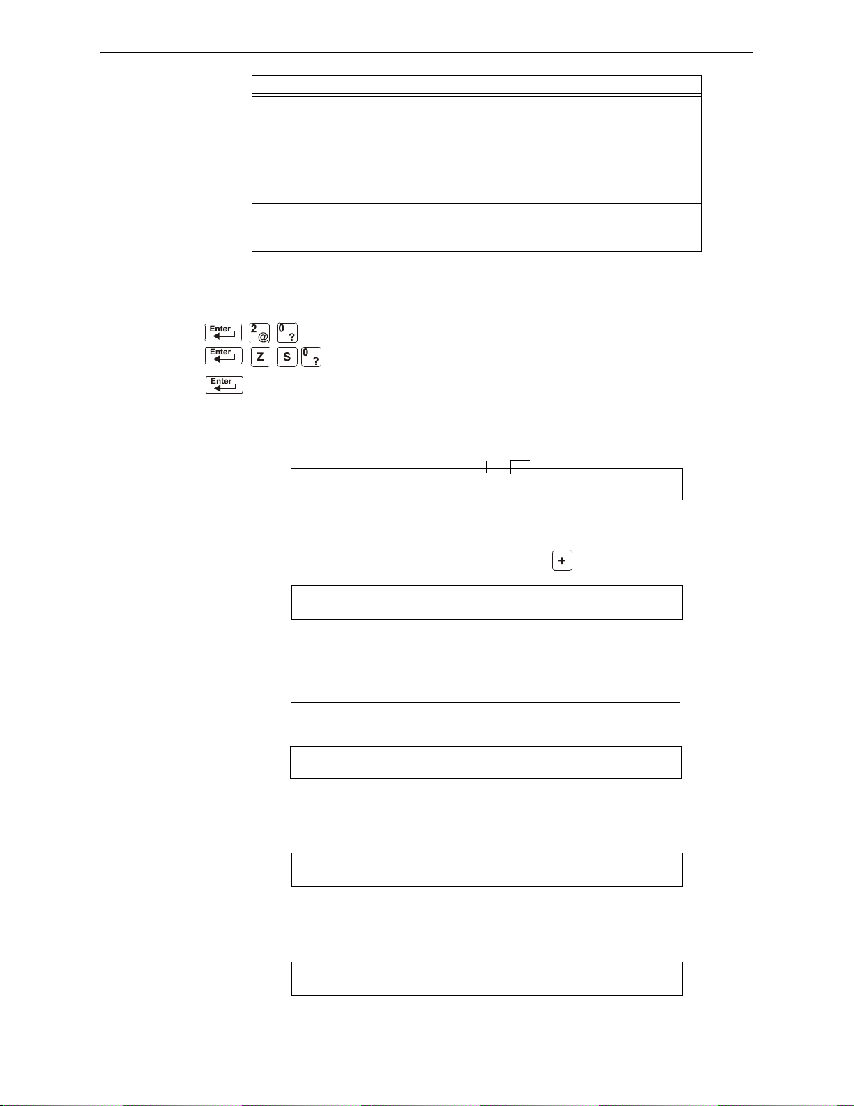
Viewing and Printing a Read Status Read Status Operation
A1=Address
ACS selection group
ANNUN SELECTION1: A1=H A2=* A3=* A4=*
A5=* A6=* A7=* A8=* A9=* A10=* A11=*
S1
ANNUN SELECTION2: A12=* A13=* A14=*
A15=* A16=* A17=* A18=* UDACT=N
S2
ANNUN SELECTION3: A20=* A21=* A22=*
A23=* A24=* A25=* A26=* A27=* A28=*
ANNUN SELECTION4: A29=* A30=* A31=*
A32=*
S3
S4
REGION=0 TBL.REMIND=2 ALA.SCROLL=Y
LOCAL CONTROL=1 IP ACCESS=0 DCC-MODE=N
S5
FLASHSCAN LIDET LIMOD
Y Y
S6
Parameter Description Settings
BLINK=01 The rate at which intelligent
control or monitor modules
blink during polling
ST=4 NFPA wiring style operation
for the SLC
ACS=N Use ACS Selection Groups N – No annunciator selected or
BLINK=00: No blink
BLINK=01: Devices blink on
every poll.
BLINK=16: Devices blink every
16th poll.
4 – Style 4 SLC or
6 – both Style 6 and Style 7 SLC
Y – Select and display ACS Selection
Groups
Table 4.1 System Function Parameters (2 of 2)
How to Read Status for Annunciator Selections
Annunciator Selection screens specify the information that displays
on ACS annunciators. From the “Read Status” screen, press 0, then
press the
Functions as follows: press Z, enter S, enter annunciation selection
number (1-4), press the
Status of Annunciator Selection are shown below:
ENTER key. You can now view Read Status for System
ENTER key. Sample LCD displays for the Read
Figure 4.7 Annunciator Selection 1 Screen
To view the next three annunciator selection screens, press the (NEXT SELECTION) key.
Figure 4.8 Annunciator Selection 2 Screen
If UDACT=N, the control panel displays the Annunciator Selections 3 and 4 screen, addresses
A20-A32, as shown below
:
Figure 4.9 Annunciator Selections 3 and 4 Screens
Figure 4.10 System Function Selection 5 Screen
Figure 4.11 System Function Selection 6 Screen
NFS-320/E/C, NFS-320SYS/E Operations Manual — P/N 52747:E1 06/16/2011 41
Page 42

Read Status Operation Viewing and Printing a Read Status
NODE: 000.XXX, STYLE7:N
THRESHOLD CHANNEL A:H, CHANNEL B:H
S7
SEC_RLY:1 SUP_RLY:2 BAT_SIZE:0 C_DRILL:N
TERM_DATA:0 PRT_BAUD:2 CHARGER:Y
S8
ANNUN SELECTION1: A1=H A2=C AC=* A4=*
A5=* A6=* A7=* A8=* A9=* A10=* A11=*
Figure 4.12 System Function Selection 7 Screen
• SEC_RLY and SUP_RLY (0= turn on by Fire Alarm, 1= turn on by Security, 2= turn on by
Supervisory).
• BAT_SIZE (1= battery size is greater than 26 Ahr, 0= less t han 26 Ahr).
• C_DRILL (custom drill N= No custom drill, Y= Yes).
• TERM_DATA (0= LCD80 Terminal using 7 bit data, 1= LCD80 Terminal using 8 bit data).
• PRT_BAND (0= 2400, 1= 4800, 2= 9600).
Figure 4.13 System Function Selection 8 Screen
An Annunciator Selection screen shows the information that will display on the ACS annunciators.
The table below contains the ACS display selections.
1 through 9 Programmable Annunciator #1 through #9
0 Programmable Annunciator #10
A 8 Systems points + Zo ne s 1- 5 6
B Zones 57-99, 9 F zones, 8 R zones, 4 NAC
C Loop 1, Modules 1-64
D Not Used
E Loop 1, Modules 65-128
F Not Used
G Loop 1, Modules 129-159
H Loop 1, Detectors 1-64
I Not Used
J Loop 1, Detectors 65-128
K Not Used
L Loop 1, Detectors 129-159
M Not Used
N 8 Systems points + Zones 1-56, used for r em o te station co m m un icator (TM-4)
O 8 Systems points + Zones 1-56, used for municipal box trip ou t pu t (T M -4)
Annunciator addresses 1 to 19 can be programmed to any one of the above selections. If there is a UDACT,
selections A-M will be sent to Annunciator addresses 20 to 32 respectively.
Table 4.2 ACS Selection Groups
An example of ACS selections in Annunciator Selection Screen 1:
Figure 4.14 Annunciator Selection Screen 1 Example
NOTE: An ACS selection marked with an asterisk (*) indicates no annunciator selection.
The figure above shows annunciator selections for addresses A1-A3 (addresses A4-A10, marked
with asterisks, are not selected)
42 NFS-320/E/C, NFS-320SYS/E Operations Manual — P/N 52747:E1 06/16/2011
Page 43

Viewing and Printing a Read Status Read Status Operation
Battery Voltage 27.48V Charging at XX.XXA
• Annunciators set to annunciator address 1 (A1) display the status of detectors 1-64 on SLC 1
(ACS Selection Group H)
• Annunciators set to annunciator address 2 (A2) display the status of intelligent modules 1-64
on SLC-1 (ACS Selection Group C)
How to Read Status for Battery Levels
Pressing the BATTERY LEVEL key on the NFS-320 keyboard displays information concerning the
state of the battery.
A sample LCD display is shown below.
Figure 4.15 Battery Levels
NFS-320/E/C, NFS-320SYS/E Operations Manual — P/N 52747:E1 06/16/2011 43
Page 44
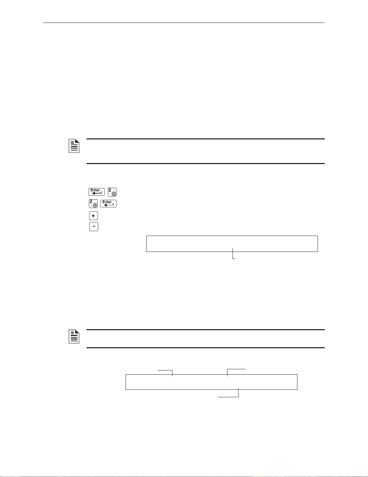
Read Status Operation Viewing and Printing a Read Status
next event
previous event
The number of events in the History buffer
EVENT HISTORY START
EVENTS IN HISTORY: 550
Time and date of the event
Type of trouble
Type of event
TROUBL IN SYSTEM GROUND FAULT
01:46P 011508 Tue
4.4.2 How to View Read Status for Event and Alarm History
Overview
The control panel maintains a History buffer of the last 800 events, each with a time and date
stamp. History events include the following:
• All alarms, troubles and operator actions, such as: Acknowledge, System Reset, Signal
Silence, Drill, and Walk Test.
• Programming entries (Program Change and Status Change, but not Read Status), along with a
number (0-9) indicating the programming submenu (for example, 0=Clear). For an example,
see
Figure 4.18.
You can view events from the Hist ory buffer in two forms: by displaying all events (option 2,
HIST=2) or by displaying alarm events only (option 4, ALARM HIST=4).
NOTE: The History buffer cont ai ns 800 events total, including the alarm events that display for
Alarm history. The control panel generates Alarm history from the alarm events that exist in the
800-event History buffer.
How to View Read Status for Event History
Option 2 (HIST=2) lets you view the total number of events in the History
buffer (up to 800 events), then view each event in chronological
sequence. From the “Read Status” screen, press 2, then press the
key to display the “Event History” screen. A sample of the Event History
screen is shown below:
ENTER
Figure 4.16 Sample Event History Display
To display events in the History buffer, do the following:
• Press the NEXT SELECTION key to step through each event from the first entry (oldest event
first) in the History buffer, or
• Press the PREVIOUS SELECTION key to step through each event from the most recent entry in the
History buffer.
NOTE: The NEXT SELECTION key will show the most recent event first, and then move to its
normal function of displaying the oldest events first.
A sample LCD display for a trouble event:
Figure 4.17 Sample Trouble Event Display
44 NFS-320/E/C, NFS-320SYS/E Operations Manual — P/N 52747:E1 06/16/2011
Page 45
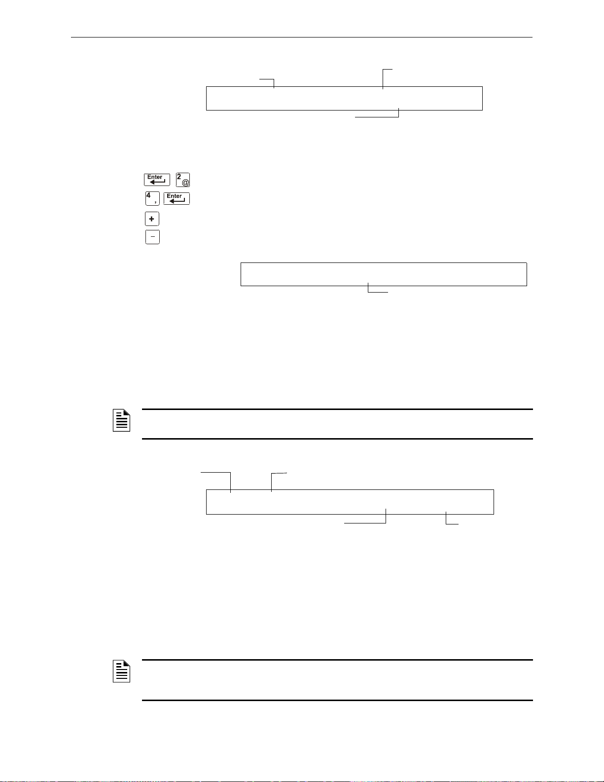
Viewing and Printing a Read Status Read Status Operation
Message specifies the
Program Change option used
Type of event
Time and date of the event
PROGRAM CHANGE 5=ZONE LABEL CHG
01:51P 011508 Tue
next event
previous event
The number of alarms in the History buffe
ALARM HISTORY START (ESCAPE TO ABORT)
ALARMS IN HIST: 073
Type Code of the device
that alarmed
Type of event
(ALARM)
SLC address of the
device that alarmed
Time and date of the alarm
ALARM: PULL_STATION INTENSIVE CARE UNIT
EASTERN WING Z004 03:10P 011508 1M147
A sample LCD display for a Program Change event:
Figure 4.18 Sample Program Change Event Display
How to View Read Status for Alarm History
Option 4 (ALARM HIST=4) lets you view the total number of alarms in
the History buffer (up to 200), then view each alarm in chronological
sequence. From the “Read Status” screen, press 4, then press the
key to display the “Event History” screen. A sample Alarm History
screen is shown below:
Figure 4.19 Sample Alarm History Display
ENTER
To display alarms in the buffer, do the following:
• Press the NEXT SELECTION key to step through each alarm from the first entry (oldest alarm
first) in the buffer, or
• Press the PREVIOUS SELECTION key to step through each alarm from the most recent entry in
the buffer
NOTE: The NEXT SELECTION key will show the most recent event first, and then move to its
normal function of displaying the oldest events first.
A sample display for an alarm event:
Figure 4.20 Sample Alarm Event Display
4.4.3 How to Print Points, Event and Alarm History
Overview
Read Point options 1, 3, and 5 in the “Read Status” screen let you pri n t po ints, event history, and
alarm history . This section contains instructions for printing, as well as sample point, event history,
and alarm history printouts.
NOTE: Before printing, make sure your control panel is connected to a compatible printer and
the printer is configured according to the manufacturer’s specifications, and that the correct baud
rate is selected at the panel.
NFS-320/E/C, NFS-320SYS/E Operations Manual — P/N 52747:E1 06/16/2011 45
Page 46
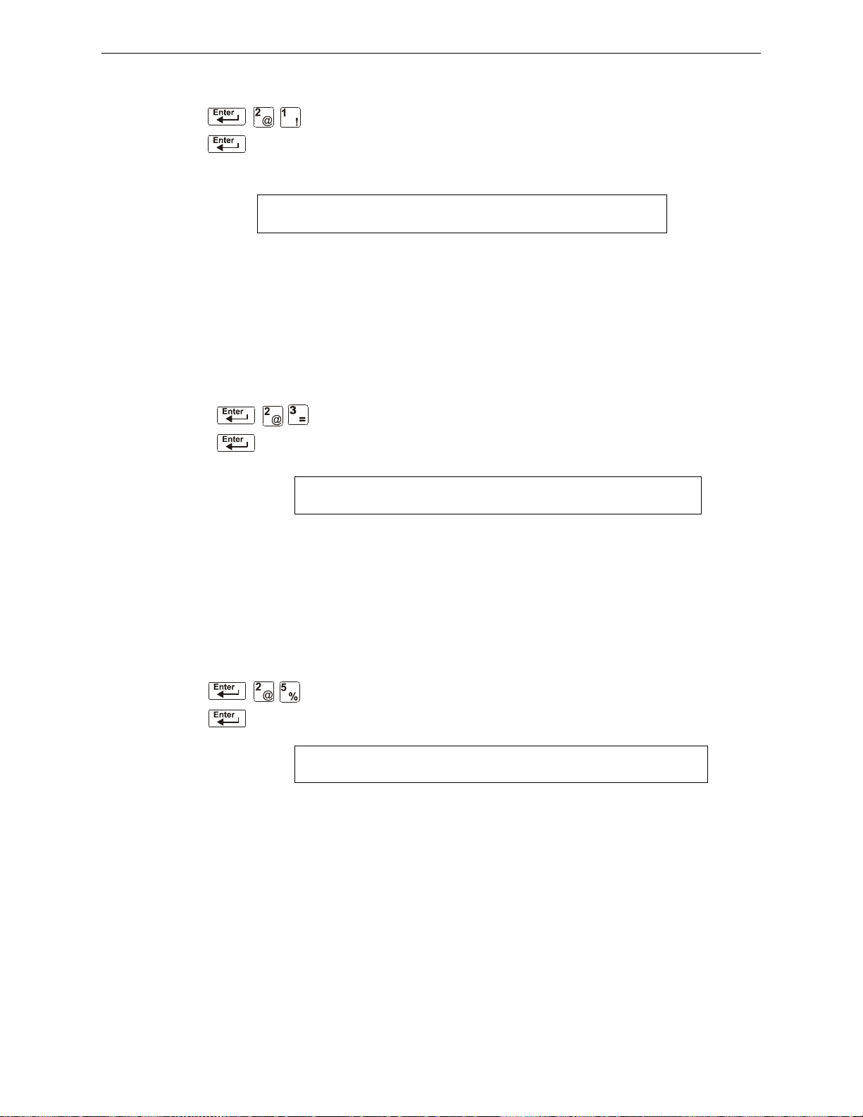
Read Status Operation Viewing and Printing a Read Status
STATUS PRINT
NORMAL SMOKE(PHOTO) DETECTOR ADDR 1D043 Z003 000%A8 8 ** 1D043
NORMAL SMOKE(PHOTO) DETECTOR ADDR 1D044 Z003 000%A8 8 ** 1D044
NORMAL SMOKE(PHOTO) DETECTOR ADDR 1D045 Z003 000%A8 8 ** 1D045
HISTORY PRINT
******************** EVENT HISTORY START****************************************
SYSTEM RESET 02:28P 011508 Tue
ALARM: SMOKE (ION) DETECTOR ADDR 1D075 Z002 02:28P 011508 1D075
ALARM: SMOKE (ION) DETECTOR ADDR 1D076 Z002 02:28P 011508 1D076
ACKNOWLEDGE 02:28P 011508 Tue
ALARM HISTORY PRINT
********************ALARM HISTORY START ****************************************
ALARM: SMOKE (ION) DETECTOR ADDR 1D075 Z002 02:28P 011508 1D075
ALARM: SMOKE (ION) DETECTOR ADDR 1D076 Z002 02:28P 011508 1D076
******************* PRINT END ****************************************
How to Print Points
Option 1 (PRNT POINT=1) lets you print a list of all points programmed into
the system. From the “Read Status” screen, press 1, then press the ENTER
key to print a list of installed points. A sample Print Point screen is shown
below:
Figure 4.21 Sample Print Point Display
A sample printout of three points using the Print Point option:
How to Print Event History
Option 3 (HIST=3) lets you print a list of all events in the History buffer (up
to 800). From the “Read Status” screen, press 3, then press the ENTER key to
print a list of events. A sample History Print screen is shown below:
Figure 4.22 Sample History Print Screen
A sample printout of three events in history using the History Print option:
How to Print Alarm History
Option 5 (ALARM HIST=5) lets you print a list of alarm events in the History
buffer (up to 200). From the “Read Status” screen, press 5, then press the
ENTER key to print a list of alarm events. A sample Print Alarm History
screen is shown below:
Figure 4.23 Sample Print Alarm History Display
A sample printout of two alarm events in the History buffer using the Print Alarm History option.
46 NFS-320/E/C, NFS-320SYS/E Operations Manual — P/N 52747:E1 06/16/2011
Page 47
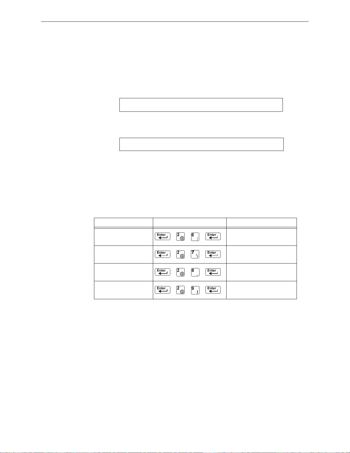
Viewing and Printing a Read Status Read Status Operation
HISTORY EMPTY (ESCAPE TO ABORT)
****************************************
ALARM HISTORY EMPTY (ESCAPE TO ABORT)
****************************************
4.4.4 How to View and Print Hidden Event and Alarm History
The control panel maintains a copy of the History buffer. For instance, if someone clears the
History buffer using Status Change programming option 4, the control panel retains a copy of the
History buffer. The copy of the preceding History buffer is called a Hidden History buffer and a
copy of the preceding Alarm History is called a Hidden Alarm History buffer.
If you attempt to view or print history and the control panel displays one of the screens shown
below you can use the options listed in the table below to view the contents of a Hidden History
buffer.
Figure 4.24 History Empty Display
Figure 4.25 Alarm History Empty Display
Options for viewing and printing Hidden History and Hidden Alarm History do not appear in the
LCD display when in Read Status. You can view and print the contents of these Hidden History
buffers using the options listed in the table below. You read and print Hidden History and Hidden
Alarm History the same way you read and print history using the options that appear on the “Read
Status” screen. The table also contains references to the sections that contain instructions for
reading and printing history.
To Press Refer to
Read Hidden Alarm History “How to View Read Status for
Alarm History” on page 45
Print Hidden Alarm History “How to Print Alarm History” on
page 46
Read Hidden History “How to View Read Status for
Print Hidden History “How to Print Event History” on
Event History” on page 44
page 46
Table 4.3 Hidden History Selections
NFS-320/E/C, NFS-320SYS/E Operations Manual — P/N 52747:E1 06/16/2011 47
Page 48

Notes
48 NFS-320/E/C, NFS-320SYS/E Operations Manual — P/N 52747:E1 06/16/2011
Page 49
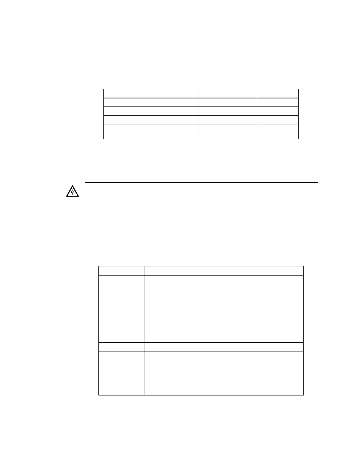
Appendix A: Special Zone Operation
!
A.1 Overview
This section contains information for operating the control panel as detailed in the topics listed
below:
Section Special Zone Refer to Page
A.2, "Releasing Zones (R0-R9)" R0-R9 page 49
A.3, "Time, Date, and Holiday Functions" F5, F6, F7 page 52
A.4, "NAC Coding" F8 page 54
A.5, "Presignal and Positive Alarm
Sequence (PAS) Operation"
A.2 Releasing Zones (R0-R9)
A.2.1 Purpose of Releasing Zones
WARNING: When used for CO2 releasing applications, observe proper precautions as stated
in NFPA 12. Do not enter the protected space unless physical lockout and other safety
procedures are fully completed.
Do not use software disable functions in the panel as lockout.
F0 page 55
The control panel provides ten Releasing Zones (R0-R9). These are special zones that you can use
for up to ten independent releasing operations. This section contains descriptions of each Releasing
Function option and an example of how Releasing Zone options work.
For instructions on programming Releasing Functions, refer to the NFS-320 Programming Manual.
Each Releasing Zone includes the following releasing options:
Option Description
Cross Zone Cross Zones let you program the control panel to activate a Releasing
Zone when two or more initiating devices are alarmed. Cross Zone
selections are:
Y Two or more detectors are alarmed that are mapped to one of the ten
Releasing Zones (R0-R9)
Z Two or more detectors are alarmed that are mapped to two different
Software Zones and mapped to one of the ten Releasing Zones (R0-R9).
H At least one smoke detector mapped to one of the ten Releasing Zones
(R0-R9) is alarmed and at least one heat detector mapped to the same
Releasing Zone as the smoke detector is alarmed.
N Cross Zones not used
Delay Timer Select a 0–60 second delay before activating a zone.
Abort An Abort Switch Type Code used to abort activation of a zone.
Manual Release Allows immediate zone activation by overriding the abort function,
cross-zone function, and delay timer.
Soak Timer Automatically shuts off the releasing device after a preprogrammed period
of time. Select 0001-9999 seconds for a Soak Timer or 0000 seconds for
no Soak Timer.
Table A.1 Releasing Options
NFS-320/E/C, NFS-320SYS/E Operations Manual — P/N 52747:E1 06/16/2011 49
Page 50
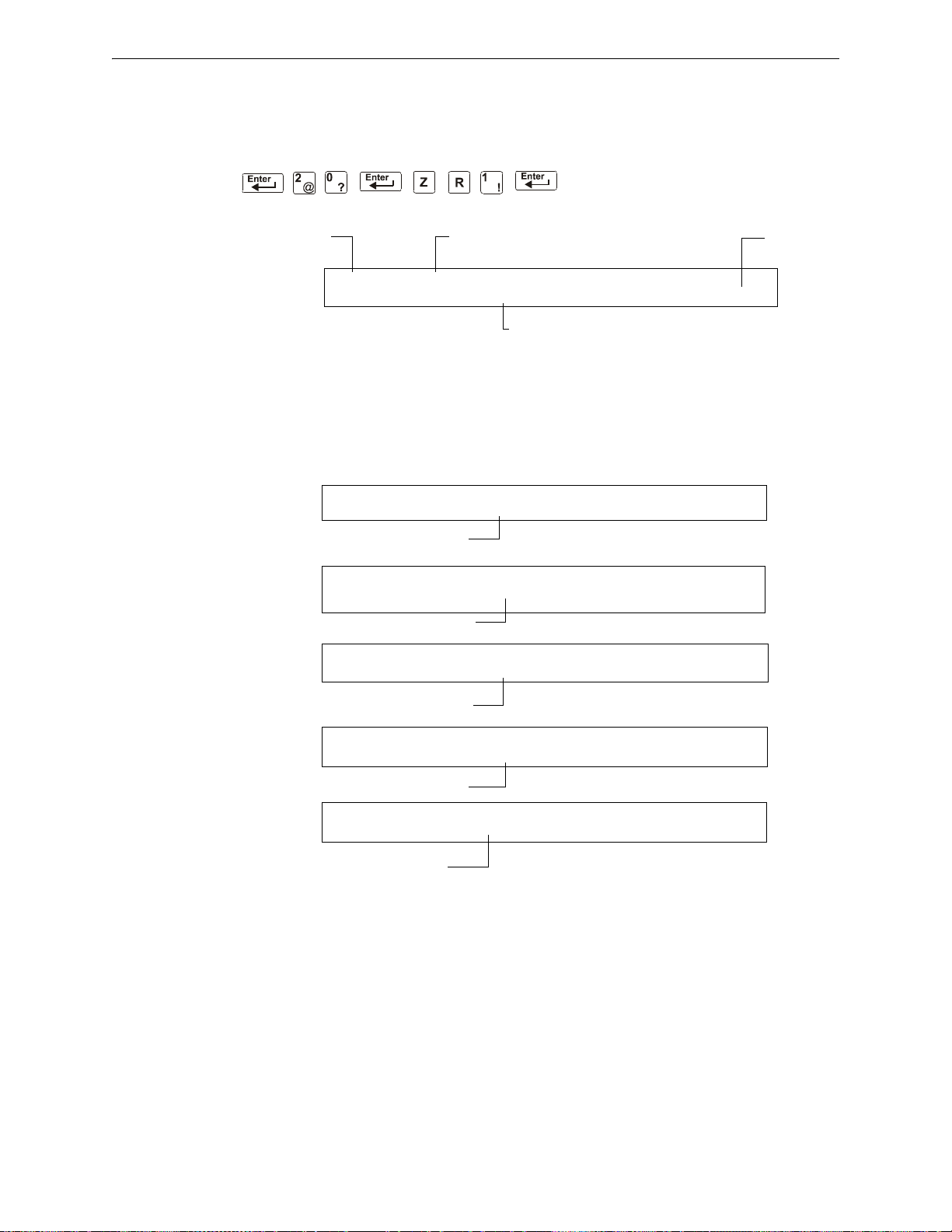
Special Zone Operation Releasing Zones (R0-R9)
Releasing Function status banner Status (On or Off)
Releasing
Zone R1
Abort Function selection for the Releasing Zone
OFF RELEASE FUNCT RELEASE CONTROL
DELAY=00 ABORT=ULI CROSS=N SOK=0000 R01
CBE list = O1 R1
CBE list = O1 R1
CBE list = O2 R1
CBE list = 02 R1
CBE list = R1
PROGRM SMOKE(PHOTO) DETECTOR ADDR 2D101
01 R1 __ __ __A8P8** 2D101
PROGRM SMOKE(PHOTO) DETECTOR ADDR 2D102
01 R1 __ __ __A8P8** 2D102
PROGRM SMOKE (ION) DETECTOR ADDR 2D103
02 R1 __ __ __A8P8** 2D103
PROGRM HEAT(ANALOG) DETECTOR ADDR 2D104
02 R1 __ __ __A8P8** 2D104
PROGRM RELEASE CKT FRONT HALLWAY NO. 3
R1 __ __ __ __ I** B03
A.2.2 How to View Releasing Zone Selections
You can use the Read Status Entry option to view the current selections for a Releasing Zone. For
example, to view selections for Releasing Zone R1, press the keys in sequence:
A sample LCD display of a Releasing Function selected for Releasing Zone R1:
Figure A.1 Sample Read Status for a Releasing Zone
A.2.3 How Releasing Zones Operate
The figure below contains an illustrated example of how Releasing Zones work, using cross zone
selections with four detectors and a NAC mapped to Releasing Zone 1 (listed as ZR1 in the CBE
list).
Table A.2 lists the cross zone selections and the conditions that activate the Releasing Zone:
50 NFS-320/E/C, NFS-320SYS/E Operations Manual — P/N 52747:E1 06/16/2011
Page 51

Releasing Zones (R0-R9) Special Zone Operation
Releasing
Zone ZR1
Software
Zone Z02
Software
Zone Z01
Smoke
Detector
2D101
Smoke
Detector
2D103
Heat
Detector
2D104
Smoke
Detector
2D102
NAC
B03
CBE list = Z02 ZR1
CBE list = Z01 ZR1
CBE list = Z01 ZR1
Figure A.2 Illustrated Example of Cross Zone Programming
Listing of each Cross Zone option and the conditions required to activate the Releasing Zone,
according to the example shown in
Cross Zone Selection
(Cross=)
Cross=N An alarm from any initiating devices activates the releasing circuit.
Cross=Y An alarm from any two initiating devices activates the releasing circuit.
Cross=Z An alarm from two initiating devices mapped to different Software Zones,
Cross=H Activation of heat detector 2D104 and one smoke detector (2D101,
Figure A.2.
Condition(s) Required to Activate the Releasing zone
but mapped to the same Releasing Zone.
• An alarm from 2D101 and 2D103 – detectors mapped to different
zones, but both list ZR1 in their CBE.
• An alarm from 2D102 and 2D104 – detectors mapped to different
zones, but both list ZR1 in their CBE.
• An alarm from 2D101 and 2D104 – detectors mapped to different
zones, but both list ZR1 in their CBE.
• An alarm from 2D102 and 2D103 – detectors mapped to different
zones, but both list ZR1 in their CBE.
2D102, or 2D103).
Table A.2 Example of Cross Zone Selections
NFS-320/E/C, NFS-320SYS/E Operations Manual — P/N 52747:E1 06/16/2011 51
Page 52
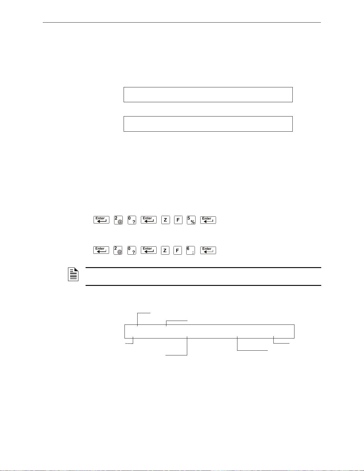
Special Zone Operation Time, Date, and Holiday Functions
USA Time and Date format (default)
EUR Time and date format
TROUBL CONTROL MODULE ADDR 1M159
OPEN 03:48P 011508 1M159
TROUBL CONTROL MODULE ADDR 1M159
OPEN 15:48 150108 1M159
Status ON (ON time in effect)
Time Function status banner
Zone F5
ON time for
devices that list
F5
OFF time for devices
that list F5
Day-of-week selections
(H=holiday selected)
ON TIME FUNCTION TIME CONTROL
ON=07:00 OFF=15:00 DAYS=SMTWTF*H F05
A.3 Time, Date, and Holiday Functions
A.3.1 Overview
The control panel includes a real-time clock that displays the time-of-day, the date, and the
day-of-week. The clock includes a lithium battery backup. Time displays in a USA format (12-hour
time format with month/day/year) or a EUR (European) format as shown below:
Figure A.3 Sample USA and EUR Time/Date Formats
The control panel also provides Time Control zones F5 and F6 for time and date control functions
and zone F7 for holiday functions.
A.3.2 How to View Time Control Selections
You can use the Read Status Entry option to view the current selection for the Time function. To do
so, press the following keys in sequence:
or
NOTE: For instructions on programming the Time function, refer to the NFS-320 Programming
Manual.
The LCD display shows the current selections for the Time Control function. The figure below
shows a sample LCD display of a Time Control function:
Figure A.4 Sample Read Status for Time Function
52 NFS-320/E/C, NFS-320SYS/E Operations Manual — P/N 52747:E1 06/16/2011
Page 53
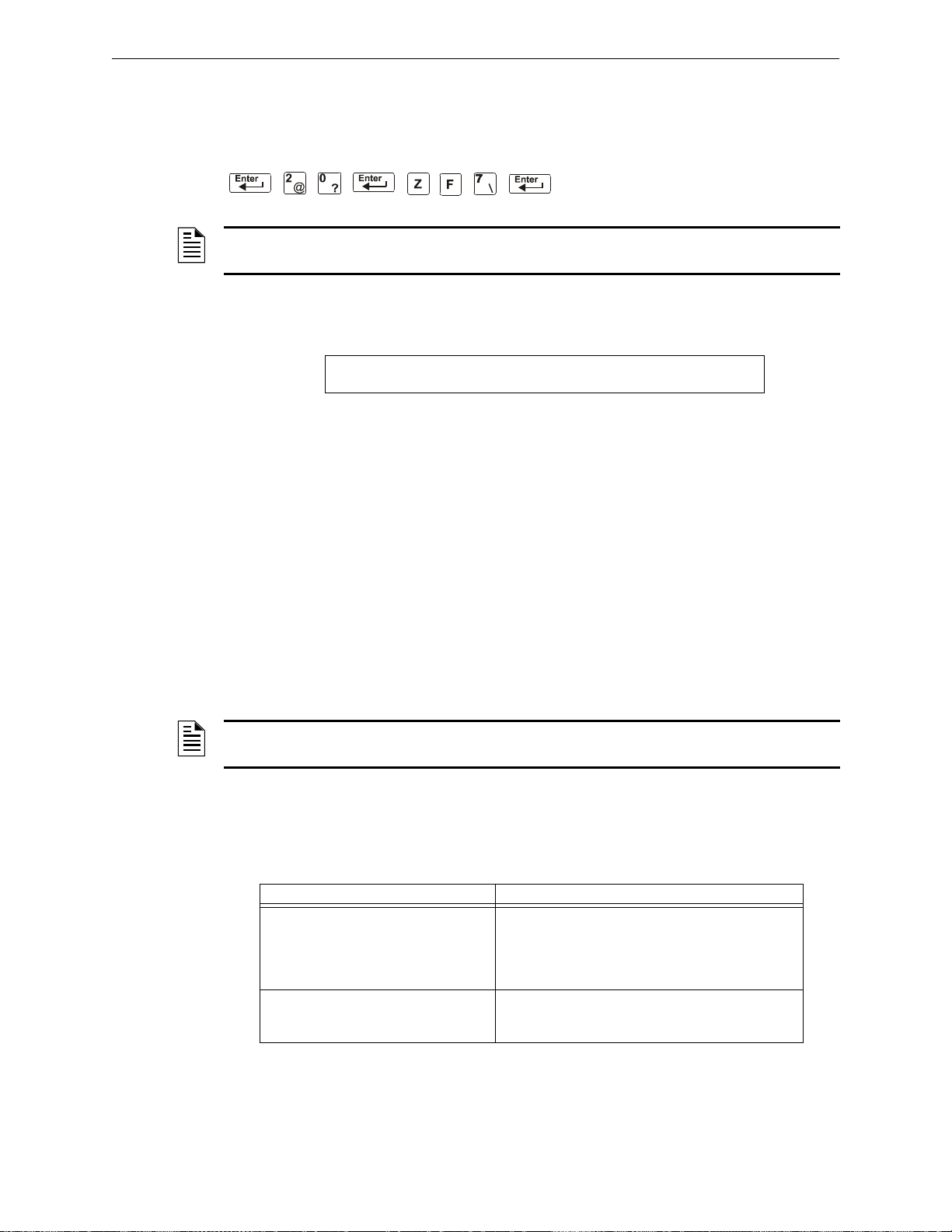
Time, Date, and Holiday Functions Special Zone Operation
Status ON (holiday function not in effect)
Holiday Function status banner
Holiday selections (for zone F7)
ON HOLIDAY FUNCTION 12/15 **/** **/**
**/** **/** **/** **/** **/** **/**
A.3.3 How to View Holiday Function Selections
You can use the Read Status Entry option to view the current selection for the Holiday function. To
do so, press the following keys in sequence:
NOTE: For instructions on programming the Hol i da y fu nction, refer to the NFS-320
Programming Manual.
The LCD display in Figure A.5 gives an example of an LCD display of a Holiday function:
Figure A.5 Sample Read Status for Holiday Function
A.3.4 How Time Control and Holiday Functions Work
Time and Holiday activation occurs automatically and does not require operator intervention. All
outputs with a CBE list containing F5 or F6 activate within the times specified for the days of the
week listed in F5 or F6. All smoke detectors with a CBE list containing F5 or F6 switch to their
lowest sensitivity (AL:9) within the times specified for the days of the week listed in ZF5 or ZF6.
Refer to “Intelligent Sensing Applications” in the NFS-320 Programming Manual for details on
setting detector sensitivity.
Time Control is active for all days of the week listed in F5 or F6. Holidays listed in F7 are excluded
unless you list Holidays (H) in the day-of-week selection of F5 and F6 (shown in
Figure A.4). Enter
the time functions in a 24-hour format with the OFF time later than the ON time. After changing
programming using Time Control, always reset the control panel.
NOTE: You can turn a NON FIRE control point on and off, by listing zone F5 or F6 in the CBE list
of a control/relay module.
You can use Time Control zones F5 and F6 to program non-fire applications such as turning lights
on and off, setting a thermostat, and so on. For example, you can program zones F5 and F6 to
activate outputs at one time of day and deactivate outputs at later time, on specified days of a week.
Table A.3 contains descriptions of additional Time Control applications:
Application Requirement
Control day and night sensitivity of
intelligent, addressable detectors
Control a specific date of year Input up to nine date in the Holiday selection screen
List zone F5 or F6 in the detector CBE. This
automatically sets the detector sensitivity to the
minimum setting (AL:9) during the day and
automatically returns detector sensitivity to
programmed sensitivity during the evening.
for Special Zone F7, then list zone F7 (Holiday) in the
CBE of a device.
Table A.3 Time Control Applications
NFS-320/E/C, NFS-320SYS/E Operations Manual — P/N 52747:E1 06/16/2011 53
Page 54
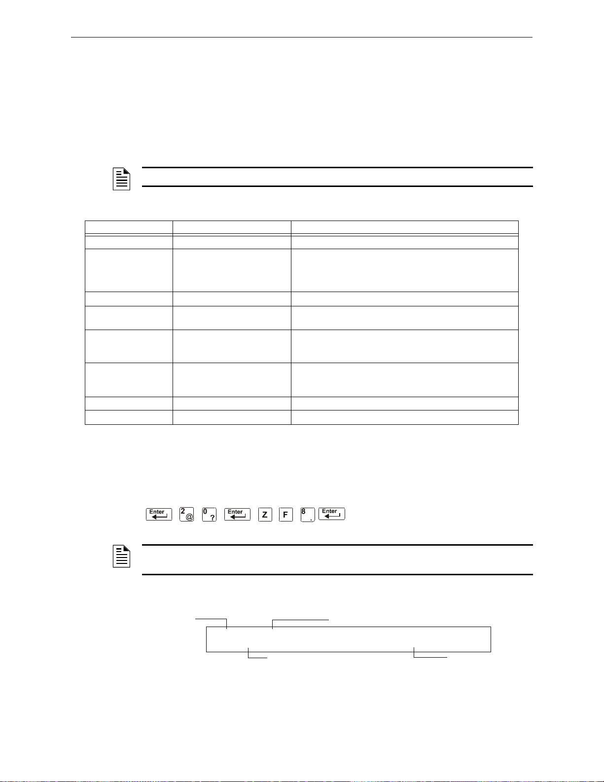
Special Zone Operation NAC Coding
Status
Coding Function status banner
Zone F08
Coding selection
OFF CODING FUNCTION CODE TYPE
MARCH TIME F08
A.4 NAC Coding
A.4.1 Overview of Coding
A Coding selection is the Code Type that pulses when the control panel activates a NAC mapped to
Special Zone F8. Special Zone F8 provides seven coding selections (see
in the CBE of a NAC. To use a Code Type, program a NAC to list Zone F8 (reserved for a Code
Type) in the NAC CBE list.
NOTE: Control modules (FCM-1, FRM-1) cannot be coded.
The table below contains descriptions of the signals that correspond to each NAC Code Type:
Coding Selection Signal Notes
March Time (default) 120 PPM (pulses Per minute) Default selection for NACs mapped to F8.
Two-Stage Alert signal (20 PPM) or
General Alarm signal (T emporal
pattern)
California 10 sec. On, 5 sec. Off, repeats n/a
Temporal 0.5 on, 0.5 off, 0.5 on, 0.5 off,
0.5 on, 1.5 off, repeats
Canadian Dual Stage
(3 minutes)
Canadian Dual Stage
(5 minutes)
System Sensor Strobe Synchronizes System Sensor ADA horn/strobes.
Gentex Strobe Synchronizes Gentex horns/strobes.
Alert signal (20 PPM)
Drill Switch activation switches
to Temporal pattern
Alert signal (20 PPM)
Drill Switch activation switches
to Temporal pattern
Alert signal – When an alarm occurs and not activated by
another zone, the output pulses at 20 PPM.
General Alarm signal – If not acknowledged within 5 minutes,
the control panel switches from 20 PPM to Temporal pattern.
Used as a standard general EVAC signal.
Same as Two-Stage except will only switch to second stage by
activation of Drill Switch three minute timer.
Same as Two-Stage except will only switch to second stage by
activation of Drill Switch five minute timer.
T able A.4) that you can list
Table A.4 F8 Code Types and Audio Signals
A.4.2 How to View Coding (F8) Selections
You can use the Read Status Entry option to view the current selecti on for the Coding function. To
do so, press the following keys in sequence:
NOTE: For instructions on programming the Coding function, refer to the NFS-320 Programming
Manual.
The LCD display shows the current selections for the Code T ype. Figure A.6 shows a sample LCD
display of a Code Type selection of March Time:
Figure A.6 Sample Read Status for Coding Function
54 NFS-320/E/C, NFS-320SYS/E Operations Manual — P/N 52747:E1 06/16/2011
Page 55
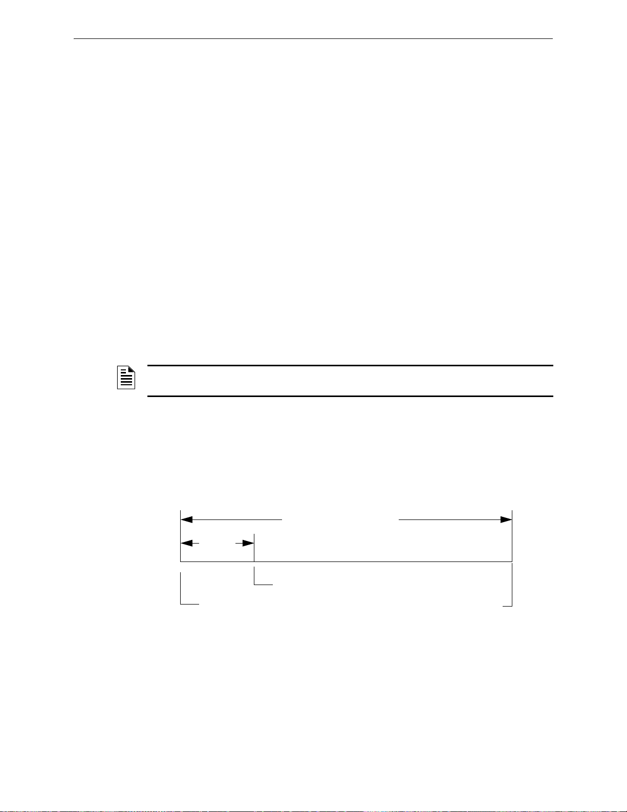
Presignal and Positive Alarm Sequence (PAS) Operation Special Zone Operation
Initial alarm
annunciation
Alarm activates outputs,
if panel is not reset.
If PAS=Y, alarm activates
outputs if not acknowledged
PAS (15s)
Presignal Delay Timer (60-180)
A.4.3 How to Respond to an Alarm with Coding
If an alarm occurs with a Coding selection, the control panel latches the control panel in alarm and
pulses outputs mapped to F8 at the pulse specified by the Coding selection (see
Table A.4). To
silence the outputs, press the SIGNAL SILENCE key.
A.5 Presignal and Positive Alarm Sequence (PAS) Operation
A.5.1 Overview
This section describes the Presignal and PAS selection, and provides instructions on how to do the
following:
• View Presignal and PAS selections
• Respond to an alarm with Presignal
• Operate the control panel with a Presignal Delay Timer only
• Operate the control panel with a Presignal Delay Timer and PAS
A.5.2 What is Presignal and PAS?
Presignal is a feature that initially causes alarm signals to only sound in specific areas, monitored
by qualified persons. This allows delay of the alarm from 60 to180 seconds after the start of alarm
processing. The control panel Presignal feature provides two selections:
NOTE: Presignal differs from the Alarm Verification Timer which does not require human
intervention.
• A Presignal Delay Timer (60-180 seconds) that delays activation of all outputs with a CBE that
includes Special Zone F0.
• A PAS selection, in addition to the Presignal Delay Timer, that allows a 15-second time period
for acknowledging an alarm signal from a fire detection/initiating device. If the alarm is not
acknowledged within 15 seconds, all local and remote outputs activate immediately and
automatically.
An illustration of Presignal and PAS timing.
Figure A.7 Presignal and PAS Time
NFS-320/E/C, NFS-320SYS/E Operations Manual — P/N 52747:E1 06/16/2011 55
Page 56
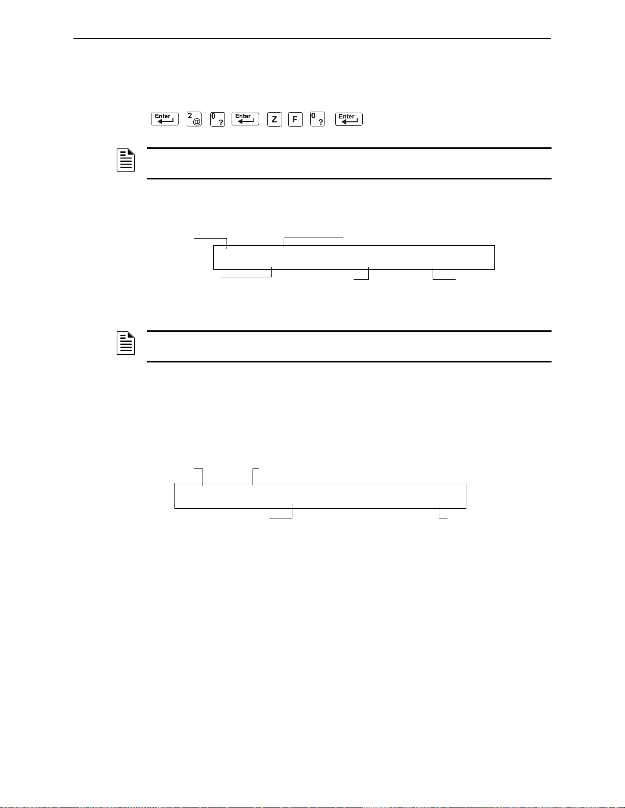
Special Zone Operation Presignal and Positive Alarm Sequence (PAS) Operation
Status Off
Presignal Function status banner
Presignal Delay=60
Seconds
PAS selected
Zone F00
OFF PRESIGNAL FUNCT PRESIGNAL DELAY
DELAY-060 PAS=YES FOO
Status banner ALARM
Type Code
MONITOR
SLC address of the
activated initiating device
First zone in the CBE list
(blank if no zone listed)
ALARM: MONITOR MODULE ADDR 1M147
Z004 10:14A 011508 1M147
A.5.3 How to View Presignal and PAS Selections
You can use the Read Status Entry option to view the current selection for the Presignal function.
To do so, press the keys in sequence:
NOTE: For instructions on programming the Presignal function, refer to the NFS-320
Programming Manual.
The LCD display shows the current selections for the Presignal function. The figure below shows a
sample LCD display of a Presignal function selected for PAS and a Presignal Delay Timer of 60
seconds:
Figure A.8 Sample Read Status for Presignal Function
NOTE: If any monitor modules are programmed with a PAS INHIBIT Type Code and a fire alarm
occurs, zone F0 goes false and aborts the Presignal Delay Timer.
A.5.4 How to Respond to an Alarm with Presignal Delay Timer (no P AS)
If an alarm occurs with a Presignal Delay Timer (60-180 seconds), the control panel displays the
type of device and the SLC address of the device causing the alarm. If a second alarm occurs during
the Presignal Delay Timer, the control panel aborts the Presignal Delay Timer and activates all
programmed outputs. A sample Alarm screen for a monitor module is shown below:
Figure A.9 Sample Alarm Display Screen
The FIRE ALARM LED flashes and the panel sounder pulses a steady tone. The control panel latches
until the alarm is corrected and you press the S
have the duration of the Presignal Delay Timer (60-180 seconds) to respond to the alarm before the
control panel automatically activates all outputs programmed to F0. You can take the following
actions:
• To silence the panel sounder and change the FIRE ALARM LED from flashing to steady, press
the
ACKNOWLEDGE/SCROLL DISPLAY key.
• To abort the Presignal Delay Timer, press the SYSTEM RESET key.
• T o manually activate all outputs programmed to F0, press the DRILL key. The Manual Evacuate
screen appears, the panel sounder pulses and the
steady. The Manual Evacuate screen and Alarm screen display alternately at 3-second
intervals.
YSTEM RESET key to reset the control panel. You
FIRE ALARM LED changes from flashing to
If the Presignal Delay Timer reaches its programmed value, without operator intervention, the
control panel activates all outputs programmed to F0.
56 NFS-320/E/C, NFS-320SYS/E Operations Manual — P/N 52747:E1 06/16/2011
Page 57
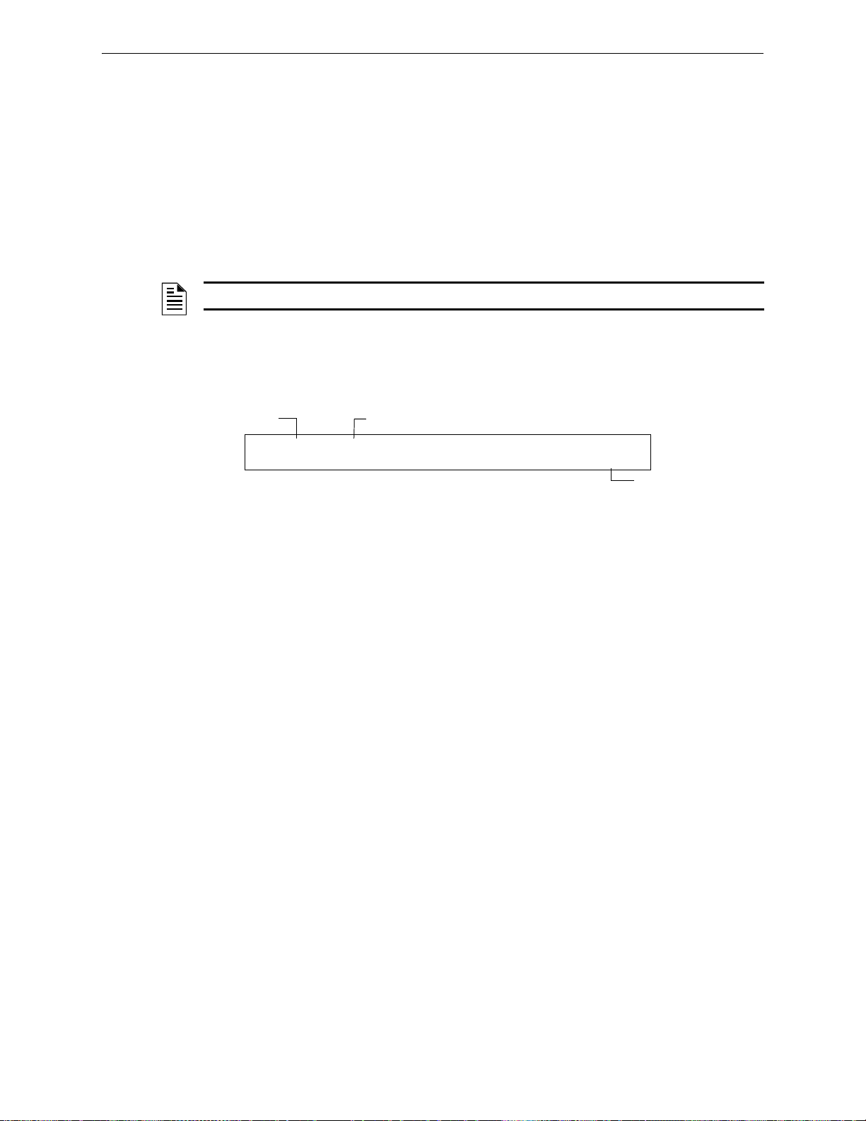
Presignal and Positive Alarm Sequence (PAS) Operation Special Zone Operation
Status banner ALARM
Type Code MONITOR
SLC address of the
activated initiating device
ALARM: MONITOR MODULE ADDR 1M147
Z004 10:14A 011508 1M147
A.5.5 How to Respond to an Alarm with Presignal Delay Timer
(PAS selected)
If an alarm occurs with a Presignal Delay Timer (60-180 seconds) and PAS selected, the control
panel displays an Alarm screen that shows the type of device and the SLC address of the device
causing the alarm. When an alarm comes from an initiating device with a CBE list that includes F0
(with PAS selected), the control panel delays the following outputs:
• System Alarm relay
• TM-4 Polarity Reversal Alarm output
• TM-4 Municipal Box output
NOTE: These outputs do not delay for Presignal operations without PAS selected.
If a second alarm occurs during the Presignal Delay Timer, the control panel aborts the Presignal
Delay Timer and activates all programmed outputs.
A sample Alarm screen for a monitor module:
Figure A.10 Sample Alarm Display Screen
The FIRE ALARM LED flashes and the panel sounder pulses a steady tone. The control panel latches
until the alarm is corrected and you press the S
have 15
seconds to acknowledge the alarm or the control panel automatically activates all outputs
YSTEM RESET key to reset the control panel. You
programmed to F0. If you acknowledge the alarm within 15 seconds, the control panel increases the
delay time to the full Presignal Delay Timer (60-180 seconds). You have the duration of the
Presignal Delay Timer to respond to the alarm before the control panel activates all outputs
programmed to F0. You can take the following actions:
• To increase the delay to the full programmed Presignal Delay Timer, press the
ACKNOWLEDGE/SCROLL DISPLAY key . The panel sounder goes silent and the FIRE ALARM LED
changes from flashing to steady.
• To abort the Presignal Delay Timer, press the SYSTEM RESET key.
• T o manually activate all outputs programmed to F0, press the DRILL key. The Manual Evacuate
screen appears, the panel sounder pulses and the
FIRE ALARM LED changes from flashing to
steady. The Manual Evacuate screen and Alarm screen display alternately at 3-second
intervals.
If the Presignal Delay Timer reaches its programmed value, without operator intervention, the
control panel activates all outputs programmed to F0.
NFS-320/E/C, NFS-320SYS/E Operations Manual — P/N 52747:E1 06/16/2011 57
Page 58
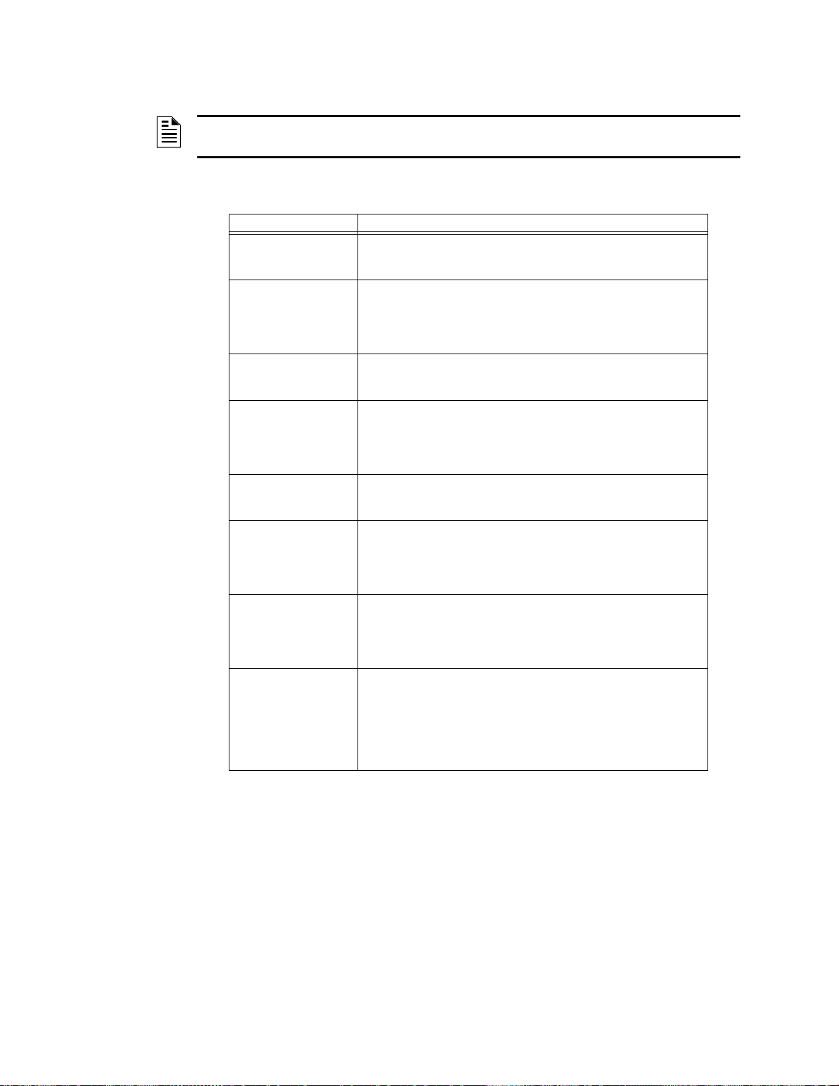
Appendix B: Intelligent Detector Functions
NOTE: For instructions on selecting Intelligent Detector Functions, refer to the NFS-320
Programming Manual.
Descriptions for Intelligent Detector Functions
Function Description
Analog Display The control panel reads and displays analog information from the 318
Sensitivity Adjust Nine selections for manually setting intelligent detector alarm levels
Day/Night Sensitivity
Operation
Maintenance Alert When compensation reaches the limit of the amount of drift
Automatic Test
Operation
Type Code
Supervision
LED Control
Operation
Alarm Verification Timer
and Verification Counter
Operation
analog detectors (159 per SLC). The display shows the sensed air at
the detector as a percentage of the alarm threshold for each detector.
within the UL range. If using ionization detectors in duct applications,
set Sensitivity Adjust to Level 1.
Refer to the NFS-320 Programming Manual for detector sensitivity
information.
Y ou can program the system to automatically force smoke detectors to
minimum sensitivity during the day. Refer to
Functions” on page 52.
compensation that can be safely applied, the control panel reports a
trouble condition, according to National Fire Alarm Code standards.
This condition also activates if the detector remains at very high or very
low measured air levels for an extended time.
The control panel performs an automatic test of each detector every
256 minutes. Failure to meet the test limits causes an Auto Test Fail
trouble.
The control panel monitors hardware device Type Codes for each
installed device at regular intervals (an interval can take up to 40
minutes for a full capacity system). If a mismatch of type compared to
the program occurs, the control panel generates a point trouble labeled
Invalid Type.
A global program selection to prevent detector LEDs from blinking as a
result of polling during normal operation. A typical application is a
sleeping area where a blinking light can distract people. As a standard
function, independent of this programming selection, the control panel
allows all LEDs to turn on in alarm.
The control panel performs alarm verification on programmed
intelligent smoke detectors. The Alarm Verification Timer is a global
program selection of 0–60 seconds (ULC installations can not exceed
30 seconds). Each detector includes a Verification Counter, which
displays the number of times that a detector entered verification but did
not time-out to alarm. The Verification Counter increments to 99 and
holds.
“Time, Date, and Holiday
Table B.1 Intelligent Detector Functions
58 NFS-320/E/C, NFS-320SYS/E Operations Manual — P/N 52747:E1 06/16/2011
Page 59

Notes
NFS-320/E/C, NFS-320SYS/E Operations Manual — P/N 52747:E1 06/16/2011 59
Page 60

Appendix C: Remote Terminal Access
C.1 General Description
The control panel can communicate with a remote terminal or computer connected to the EIA-232
PC/Terminal port. Refer to the NFS-320 Installation Manual for installation information.
NOTE: See the NFS-320 Programming Manual for instructions on enabling the CRT.
This port may be set up for interactive operation or for monitoring only. Interactive operation
requires that all equipment be UL-listed under UL Standard for Safety UL 864 and be installed and
set up as directed under Local Terminal Mode (LocT) or Local Monitor Mode (LocM).
ITE (Information Technology Equipment) equipment listed under UL 1950 is allowed for ancillary
system monitoring when the system is installed and set up as directed under Remote Terminal
Mode (RemT).
C.2 Operating Modes
The control panel provides three operating modes for the CPU EIA-232 PC/Terminal port:
• Local Terminal - LocT
• Local Monitor - LocM
• Remote Monitor - RemM
You select the operating mo de during con trol panel programming (Global System Functions). For
more information, refer to the NFS-320 Programming Manual.
The following subsections outline the functions, password requirements, and additional
information for each operating mode.
C.2.1 Local Terminal Mode (LocT)
Functions, passwords, and special requirements of Local Terminal Mode (LocT) are:
Functions: Read Status, Alter Status, and Control Functions (Table C.1).
Passwords: User-defined password for Alter Status functions.
Requirements: The terminal must be mounted in a UL 864 listed enclosure or positioned to provide
Functions available with the Local Terminal Mode:
Function Lets you...
Read Status
Alter Status
equivalent protection against unauthorized use.
• Display the status of an individual point (Detector, Module, or Zone).
• Display a list of all the points in Alarm or trouble.
• Display a list of all programmed points in the system.
• Step through the History buffer event by event.
• Display the entire History buffer.
• Disable/Enable an individual point.
• Change the sensitivity of a detector .
• Clear the verification counter of all detectors.
• Clear the entire History buffer.
• Set the Intelligent Sensing alert and action levels.
Table C.1 Local Terminal Mode Functions (1 of 2)
60 NFS-320/E/C, NFS-320SYS/E Operations Manual — P/N 52747:E1 06/16/2011
Page 61

Operating Modes Remote Terminal Access
Function Lets you...
Control Functions
• Acknowledge.
• Signal Silence.
• System Reset.
• Drill.
Table C.1 Local Terminal Mode Functions (2 of 2)
C.2.2 Local Monitor Mode (LocM)
Functions, passwords, and special requirements of Local Monitor Mode (LocM) are:
Functions: Read Status, Alter Status, and Control Functions (Table C.2).
Passwords: User-defined password for Alter Status and Control functions.
Requirements: Password security feature for Control Functions eliminates the need for mounting the
CRT-2 in an enclosure.
Functions available with the Local Monitor Mode:
Function Lets you...
Read Status
Alter Status
Control Functions
• Display the status of an individual point (Detector, Module, or Zone).
• Display a list of all the points in Alarm or trouble.
• Display a list of all programmed points in the system.
• Step through the History buffer event by event.
• Display the entire History buffer.
• Disable/Enable an individual point.
• Change the sensitivity of a detector.
• Clear the verification counter of all detectors.
• Clear the entire History buffer.
• Set the Intelligent Sensing alert and action levels.
• Acknowledge
• Signal Silence
• System Reset
•Drill
Table C.2 Local Monitor Mode Functions
C.2.3 Remote Terminal Mode (RemT)
Functions, passwords, and special requirements of Remote Terminal Mode (RemT) are:
Functions: Read Status only. See Table C.3.
Passwords: None
Requirements: Use with UL ITE-listed terminals, including personal computers with the VeriFire™
Tools or terminal emulation software. Intended for terminals connected through
modems, including FSK modems connected through a public switched telephone
network.
NFS-320/E/C, NFS-320SYS/E Operations Manual — P/N 52747:E1 06/16/2011 61
Page 62
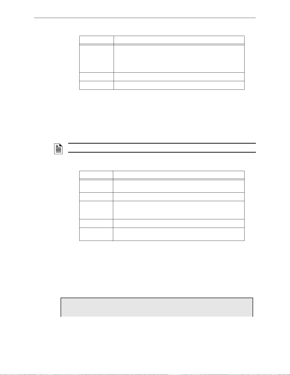
Remote Terminal Access Using the CRT-2 for Read Status
Rd Point=1, Rd Alm/Tbl=2, All Points=3, Hist:Step=4/All=5, Ala-Hist:Step=6/All=7
Functions available with the Remote Terminal Mode:
Functions Lets you...
Read Status
Alter Status
Control Functions
• Display the status of an individual point (Detector, Module, or Zone).
• Display a list of all the points in Alarm or trouble.
• Display a list of all programmed points in the system.
• Step through the History buffer event by event.
• Display the entire History buffer.
•N/A
•N/A
Table C.3 Remote Terminal Mode Functions
C.3 Using the CRT-2 for Read Status
C.3.1 Overview
This section shows how to perform Read Status functions from a CRT-2.
NOTE: See the NFS-320 Programming Manual for instructions on enabling the CRT port.
For more information see the “Read Status” section of this manual.
Function Lets you...
Read Point Read the status of any point in the system (detectors, modules, software
zones, and system parameters).
Alm/Tbl Status Display a list of all devices in the system that are in Alarm or trouble.
Read All Points Display a list of all points programmed in the system. This list will display the
History Step Step through the History buffer one event at a time.
History-All Send the entire History buffer to the CRT, from the most recent event to the
status of all addressable detectors, modules, system parameters and
software zones.
oldest event.
Table C.4 Read Status Functions
C.3.2 Accessing Read Status Options
Access the Read Status function from the CRT-2 by following these steps.
1. Turn on the CRT-2, which is connected to the control panel.
2. Press the Read Status function key . The control panel displays the “Read Status” menu options:
From the Read Status menu, you can select options 1-7.
62 NFS-320/E/C, NFS-320SYS/E Operations Manual — P/N 52747:E1 06/16/2011
Page 63
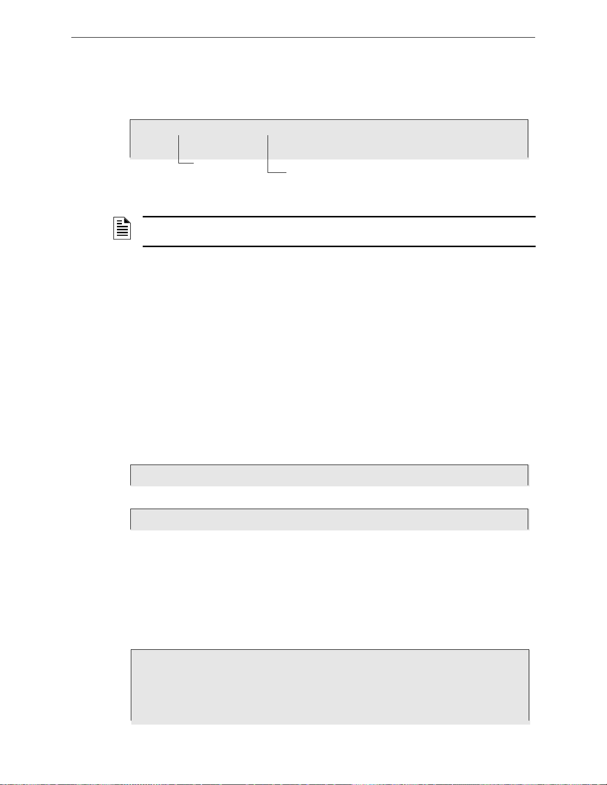
Using the CRT-2 for Read Status Remote Terminal Access
Press <1> <ENTER>
Type D(nnn), (n)M(nnn), Z(nn), F(n),, R(n), Ex, Lx or S(n) then hit Enter
Address )01-159)
Number
NORMAL SMOKE (PHOTO) INTENSIVE CARE UNIT NURSE LOUNGE Z050 020%A6 6 CV30 1D001
Press <D> <0> <0> <1> <
ENTER>
NORMAL SMOKE (PHOTO) DETECTOR ADR 1D002 Z002 000%A6 6 ** 1D002
Press <
NEXT>
TROUBL SMOKE(PHOTO) DETECTOR ADDR 1D003 INVREP 01;09P 041608 1D003
TROUBL SMOKE (ION) DETECTOR ADDR 1D004 INVREP 01;09P 041608 1D004
TROUBL HEAT(FIXED) DETECTOR ADDR 1D006 INVREP 01;09P 041608 1D006
TROUBL MONITOR MODULE ADDR 1M041 INVREP 01;09P 041608 1M041
TROUBL IN SYSTEM GROUND FAULT 01;09P 041608 Wed
TROUBL IN SYSTEM BATTERY 01;09P 041608 Wed
Press <2> <
ENTER>
C.3.3 Read Point
From the Read Status menu, select option 1 - Read Point. The CRT-2 displays the following:
Enter the following:.
NOTE: Press F5 to scroll forward through a list of devices. Press F6 to scroll back through a list
of devices.
1. Enter the first letter of the device, using upper case letters.
• Detector = “D”
• Module = “M”
• Zone = “Z”
• Special Function = “F”
• Releasing Zone = “R”
•E Zone = “E”
•L Zone = “L”
• System Parameter = “S”
2. Enter the address or number of the device.
3. Press “
ENTER”.
Example Read points for detectors 1D001 and 1D002 on SLC 1:
C.3.4 Display Devices in Alarm or Trouble
From the “Read Status” menu, select option 2 - Read Alarms/Troubles. The CRT-2 will display the
alarm and trouble history.
The semicolon, a control character in networking applications, separates the hour and minute of
events displayed from history. If events display as they occur, a colon separates the hour and
minute.
NFS-320/E/C, NFS-320SYS/E Operations Manual — P/N 52747:E1 06/16/2011 63
Page 64
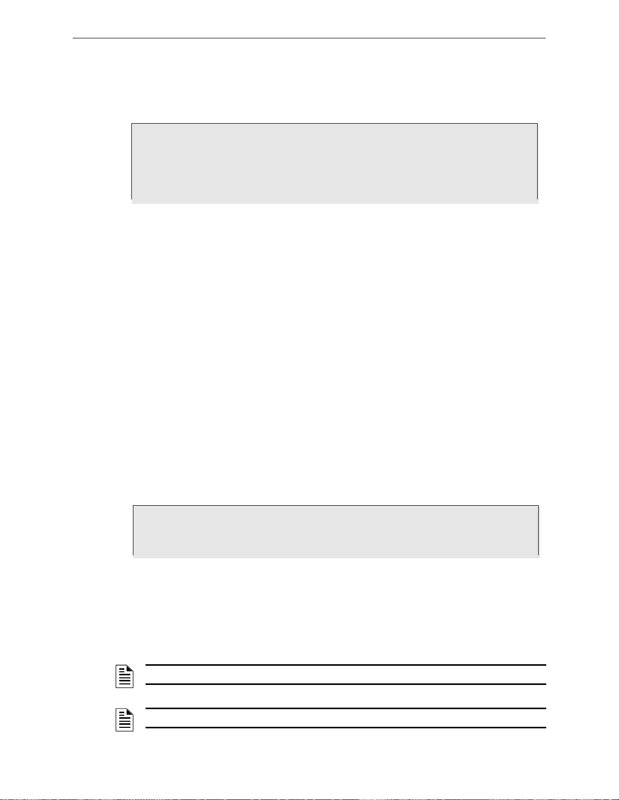
Remote Terminal Access Using the CRT-2 for Alter Status
NORMAL SMOKE(PHOTO) DETECTOR ADDR 1D002 Z003 000%A8 8 ** 1D002
NORMAL SMOKE (ION) DETECTOR ADDR 1D003 Z002 020%A6 6 ** 1D003
NORMAL HEAT(FIXED) DETECTOR ADDR 1D006 Z001 050% * 1D006
NORMAL SMOKE(LASER) DETECTOR ADDR 1D099 Z004 000%A6 6 *V00 1D099
OFF RELEASE CKT MODULE ADDR 1M001 ZR00 I** 1M001
NORMAL MONITOR MODULE ADDR 1M001 ZR00 I** 1M001
OFF RELAY MODULE ADDR 1M033 Z000 *FW 1M033
OFF SOFTWARE ZONE Zone 01 Z01
Press <3> <
ENTER>
************************ ALARM HISTORY START ***********************************
ALARM: MAN_RELEASE MODULE ADDR 1M065 10:21A 011508 1M065
ALARM: MAN_RELEASE MODULE ADDR 1M065 10:19A 011508 1M065
ALARM: MAN_RELEASE MODULE ADDR 1M065 03:20P 011508 1M065
ALARM: SMOKE (ION) DETECTOR ADDR 1D129 03:20P 011508 1M065
Press <7> <
ENTER>
C.3.5 Display All Programmed Points
From the “Read Status” menu, select option 3 - Read All Points. The CRT-2 displays a list of the
status of all addressable detectors, modules, system parameters and software zones:
C.3.6 Step-through History
From the “Read Status” menu, select option 4 - History-Step. This option lets you step through all
history events one event at a time. Step through the history list one event at a time by pressing the
Next F5 or Prior F6 function keys.
C.3.7 View All History
From the “Read Status” menu, select option 5 - History ALL. The entire history of events will
display on the screen.
C.3.8 Step-through Alarm History
From the “Read Status” menu, select option 6 - Alarm-History:Step. This option lets you step
through the panel’s alarm history one event at a time by pressing the Next F5 or Prior F6 function
keys.
C.3.9 View All Alarm History
From the “Read Status” menu select option 7 - Alarm History All. This entire history of alarm
events will display on the screen, from most recent to oldest event.
C.4 Using the CRT-2 for Alter Status
C.4.1 Overview
This section shows how to Alter Status functions from a CRT-2.
NOTE: The panel must be in Local Terminal Mode (LocT ) or Lo cal Monitor Mode (LocM).
NOTE: See the NFS-320 Programming Manual for instructions on enabling the CRT port.
64 NFS-320/E/C, NFS-320SYS/E Operations Manual — P/N 52747:E1 06/16/2011
Page 65
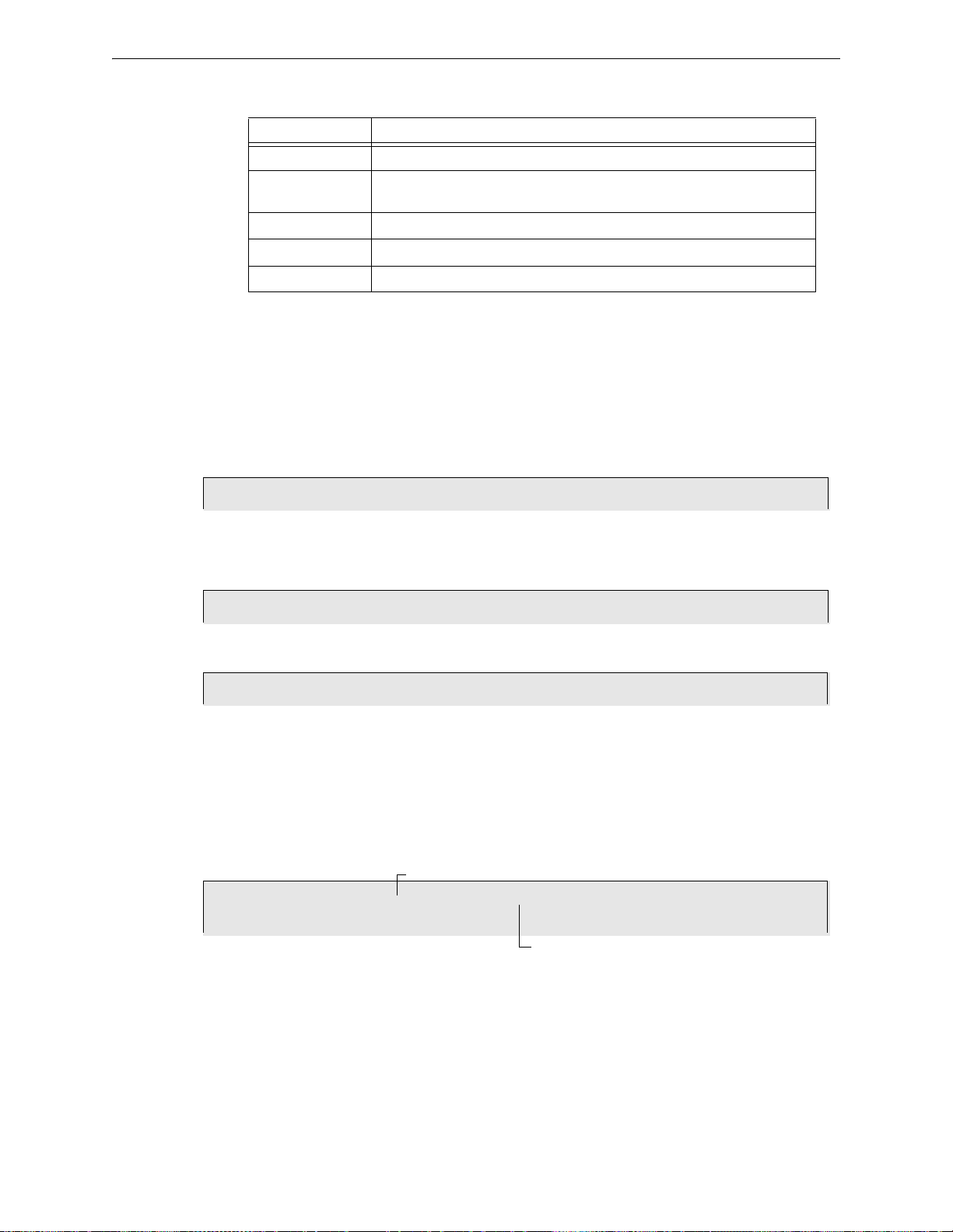
Using the CRT-2 for Alter Status Remote Terminal Access
Enter Status CHange Password or Escape to Abort
Press <
ALTER STATUS>
*****
Press <1><1><1><1><1><
ENTER>
1=Disable 2=Alarm/Prealarm 3=Clear Verification 4=Clear History 5=Alert/Action
Disable/Enable. Type D(nnn) / nMnnn / P(nn) / Z(nn) then Enter
STATUS CHANGE Dis/Ena point 8:29A Tue 01/15/08
Press <1><
ENTER>
Number
Address (01-159)
Function Lets you...
Disable Enable or disable detectors or modules.
Alarm/Pre-Alarm Change the Alarm and Pre-Alarm levels of any addressable detector in the
system.
Clear Verification Clear the verification counter for all the addressable detectors in the system.
Clear History Clear the contents of the History buffer.
Set Action/Alert Set the Pre-Alarm for Alert or Action.
Table C.5 Alter Status Functions
C.4.2 Accessing Alter St atus Options
Access Alter Status function from the CRT-2 by following these steps.
1. Turn on the CRT-2 connected to the control panel.
2. Press the Alter Status function key. The control panel displays the Password screen.
3. Enter the Status Change Password. The factory default Status Change Password is 11111.The
password does not display on the CRT-2. Five asterisks will appear in place of the password.
The Alter Status Options menu appears.
From the Alter Status Options menu, you can select 1-5.
C.4.3 Enable or Disable Detectors, Modules or Zones
From the “Alter Status” menu select option 1 - Disable. Disable lets you enable or disable
detectors, modules, or zones.
Enter the following:
1. Enter the first letter to read one of the following, using upper case letters:
2. Detector = D
Module = M
NAC = P
Zone - Z
3. Enter the address or number of the device.
NFS-320/E/C, NFS-320SYS/E Operations Manual — P/N 52747:E1 06/16/2011 65
4. Press
ENTER and a display similar to the following will appear.
Page 66
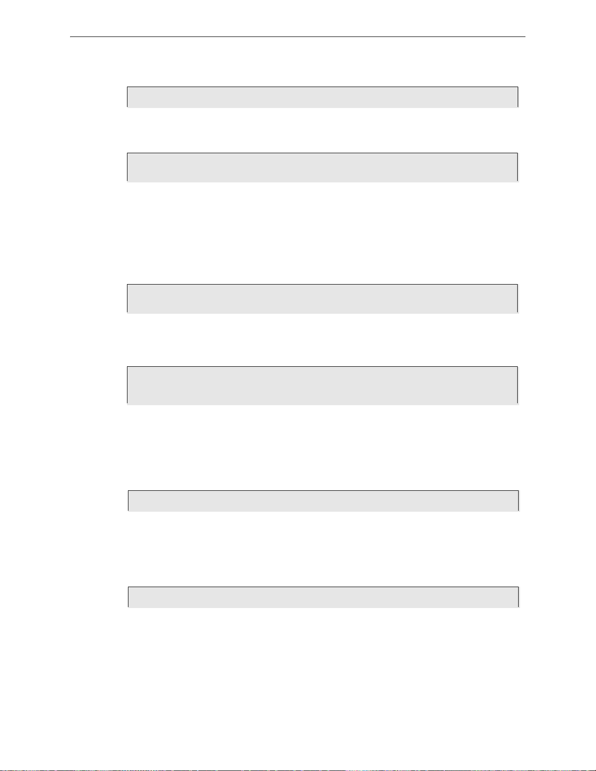
Remote Terminal Access Using the CRT-2 for Alter Status
D101 Now Enabled, Enter E(Enable) / D(Disable) or Esc. to Abort
Press <D><1><0><1><
ENTER>
Device now disabled
TROUBL SMOKE(PHOTO) DETECTOR ADDR 101 Z03 DEVICE DISABLED 08:29A Tue 01/15/08 D101
Press <D><
ENTER>
Det. Alarm/Prealarm level, type address D(
TROUBL SMOKE(PHOTO) DETECTOR ADDR 101 Z03 DEVICE DISABLED 08:29A Tue 01/15/08 D101
Press <2><
ENTER>
STATUS CHANGE Alarm/Prealarm level 08:29A Tue 01/15/08
D102 sens. at level 5, Prealarm at level 3, Enter AxPx to change, Esc. to Abort
D102 now set at new Alarm level 5 and new Pre-alarm level 2
Press <D><1><0><2><
ENTER><A><5><P><2><ENTER>
STATUS CHANGE Clear verify count 08:29A Tue 01/15/08
Press <3><
ENTER>
***************History Clear*************************
Press <4><
ENTER>
EXAMPLE Disable Detector address 101 on SLC1:
Press D to Disable (E to Enable); then press ENTER.
C.4.4 Change Alarm and Pre-Alarm Levels
This option lets you change the Alarm and Pre-alarm levels of any addressable detector in the
system. Follow these steps.
1. From the “Alter Status” menu select option 2 - Alarm/Pre-alarm.
2. Enter the address of the detector you wish to change. For example, change alarm and pre-alarm
levels for detector 102 on SLC 1 to Alarm Level 4 & Pre-alarm Level 2.
C.4.5 Clear Verification Counter
Clear verification lets you clear the verification counter for all the addressable detectors in the
system.
C.4.6 Clear the Entire History Buffer
Clear History lets you clear the entire History buffer.
66 NFS-320/E/C, NFS-320SYS/E Operations Manual — P/N 52747:E1 06/16/2011
Page 67
Using the CRT-2 for Alter Status Remote Terminal Access
Set Pre-alarm Alert (NO)/Action(YES). Type N or Y then Enter
STATUS CHANGE Change Alert/Action 08:29A Tue 01/15/08
Press <5><
ENTER>
Pre-alarm now set for ACTION
Press <Y><
ENTER>
C.4.7 Set the Pre-Alarm for Alert or Action
Set Action/Alert lets you set the Pre-alarm for Alert or Action. For example, change Pre-alarm
from “Alert” to “Action” as follows:
NFS-320/E/C, NFS-320SYS/E Operations Manual — P/N 52747:E1 06/16/2011 67
Page 68

Appendix D: Point and System Troubles Lists
There are a variety of point or system trouble types that may appear in a trouble message. The
tables below give lists of the troubles and indications of their cause.
D.1 Point (Device) Troubles
A message from the “Trouble Type” column in the following table will appear in the upper right corner of
the panel display when a point (device) trouble occurs. Use this table to help determine what the trouble is.
POINT TROUBLES
TROUBLE TYPE TROUBLE DESCRIPTION ACTION
AC FAILURE The auxiliary power supply has lost AC power. Determine whether there is an AC power loss or whether
ADRFLT Detector and new sounder base address doesn’t match. Or the ACPS
ALIGN A beam detector is in configuration mode. No action is necessary, as the trouble will clear when the
BLOCK Something has come between the detector’s beam and its reflector. Investigate and clear the blockage.
CHGFLT* The power supply’s battery charger is not working properly. Correct the fault.
CO 6MN The CO (carbon monoxide) detection element on the detector has six
CO EXP The CO (carbon monoxide) detection element on the detector has
CO TBL The CO element on the detector is not working properly. (This trouble
DIRTY 1 The detector is dirty and needs cleaning Clean the detector.
DIRTY 2 The detector requires cleaning immediate l y. It is a false alarm risk. Clean the detector immediately.
DISABL The point has been disabled. Service and re-enable the point.
GNDFLT There is a ground fault on the main or auxiliary power supply. Correct the fault.
HI BAT The auxiliary power supply’s battery charge is too high. Check the batteries for problems. Replace batteries if
INVREP The device has returned a response to the panel that the panel did not
IR TBL The infrared element is not working properly on the detector. (This
LO BAT The auxiliary power supply’s battery is low. Check the batteries for problems. Replace batteries if
LO TEMP The temperature read by a Heat+ or Acclimate™+ detector is too low. Raise the heat in the area of the detector.
LO VAL The detector chamber reading is too low; the detector is not operating
NO ANS The device (module or detector) is not responding to the poll. Either the
NO SIG The device (module or detector) is not responding to the poll. Either the
OPEN The module device has an open circuit on its supervised wiring. Check the connections from the module to the input or
PRLOSS The output module or new sounder base lost power. Turn power back on.
PSFAIL The power supply is not working properly. Check the battery for problems. Replace battery if
SHORT The module device has a short circuit on its supervised wiring. Check the connections from the module to the input or
TEST F This detector has failed the FACP’s periodic detector test for alarm
*This trouble may be fire panel or backup battery related. Test and replace backup batteries if necessary.
address is incorrect.
months left to expiration. (This trouble generates in FlashScan mode
only. CLIP mode will generate a LO VAL error.)
reached the expiration date. (This trouble gen erates in FlashScan mode
only. CLIP mode will generate a LO VAL error.)
generates in FlashScan mode only. CLIP mode will generate a LO VAL
error.)
expect.
trouble generates in FlashScan mode only. CLIP mode will generate a
LO VAL error.)
properly. Or (CLI P Mode only) t he thermist ors, CO eleme nt, or inf ra-r ed
element on
experiencing a freeze warning.
device is not working or it is not connected properly.
device is not working or it is not connected properly.
capabilities.
the detector is not working properly, or they are
Table D.1 Point (Device) Troubles (1 of 2)
the power supply and wiring is correct.
Readdress the incorrect device.
configuration is complete. However, the detector will not
detect a fire while this trouble exists.
Replace the detector.
Replace the detector.
Replace the detector.
necessary.
Check the device for functionality, addressing and wiring.
Replace the detector.
necessary.
The detector must be removed and replaced by an
authorized service representative.
Determine whether the device is functional, and
connected and addressed properly on the SLC.
Determine whether the device is functional, and
connected and addressed properly on the SLC.
output device to which it is wired.
necessary.
output device to which it is wired.
The detector should be removed and replaced by an
authorized service representative.
68 NFS-320/E/C, NFS-320SYS/E Operations Manual — P/N 52747:E1 06/16/2011
Page 69

System Troubles Point and System Troubles Lists
POINT TROUBLES
TROUBLE TYPE TROUBLE DESCRIPTION ACTION
THERM The thermistors are not functioning properly on the detector. (This
VER HI This detector, which has been programmed to participate in alarm
trouble generates in FlashScan mode only. CLIP mode will generate a
LO VAL error.)
verification, has gone into and come out of verification its programmed
limit without going into alarm. Either something is wrong with the
detector or there is a condition nearby (such as someone smoking) that
causes it to go into verification frequently.
Replace the detector.
Check the detector and the conditions nearby to
determine the problem.
Table D.1 Point (Device) Troubles (2 of 2)
D.2 System Troubles
A message from the “Trouble Type” column in the following table wil l appear in the panel display
when a system trouble occurs. Use this table to help determine the cause of the trouble.
SYSTEM TROUBLES
TROUBLE MESSAGE
TYPE
AC FAIL The main power supply has lost AC power.
ADV WALK TEST There is an Advanced Walk Test in progress. No action is required.
ANNUN x NO ANSWER The annunciator at address x is not responding. Determine whether the device is functional, and
ANNUN x TROUBLE The annunciator at address x is in trouble. Determine if the ACS module is functi onal, correctly
AUXILIARY TROUBLE An auxiliary device connected to the NFS-320 at J6 is
BASIC WALK TEST A Basic Walk Test is in progress. No action is required.
BATTERY The main power supply’s battery charge is too high or
BAT.BACKUP RAM RAM battery backup is low. Replace battery.
CHARGER FAIL* The main power supply’s battery charger is not workin g
CORRUPT LOGIC EQUAT The database that houses the panel’s logic equations
DRILL ACTIVATED Drill has been initiated. No action is required.
EPROM ERROR The a pplication and/or boot code is c orrupt. Service is required.
EXCEEDED CONN. LIMIT More than two panels have been connected to a high-
EXTERNAL RAM ERROR The external RAM test failed. Service is required.
GROUND FAULT A ground fault has occurred within the panel. Locate the ground fault and repair.
GROUND FAULT LOOP x There is a ground fault on loop x. Locate the ground fault and repair.
HS-NCM SNIFFER ACTIV The HS-NCM is in a diagnostic mode. No action is required.
INTERNAL RAM ERROR The internal RAM test failed. Service is required.
LCD80 SUPERVISORY Communication has been lost with the LCD-80. Check connections to the LCD-80 Annunciator.
LOADING.NO SERVICE A program or database download is in progre ss . The
MASTER BOX TROUBLE A TM-4 connected to a municipal box is in trouble. Reset the master box.
MASTER BOX NO ANSWER A TM-4 connected to a municipal box is not
*This trouble may be fire panel or backu p battery related. Test and replace backup batteries if necessary.
NCM COMM FAILURE Communication is lost between the NFS-320 and the
TROUBLE DESCRIPTION ACTION
Determine whether there is an AC power loss or
whether the power supply and wiring is correct.
connected and addressed prop erly.
installed, and configured prope rly.
in trouble or the cable is missing.
too low.
properly.
is corrupt. It must be re-downloaded, or all
programming must be cleared and re-e ntered.
speed network communications module.
panel is NOT providing fire protection during the
download. P
responding.
network communications module.
Check the wiring and source.
Check batteries, replace if necessary.
Correct the fault.
The database must be re-downloaded, or all
programming must be cleared and re-entere d .
Remove extra panel(s).
Proper authorities should be notif ied while a download
is in progress so that other means of fire protection
can be supplied.
Determine whether the device is functional and
connected properly.
Check to see if the NUP cable is properly installed
and the network communications module is
functional.
Table D.2 System Troubles
NFS-320/E/C, NFS-320SYS/E Operations Manual — P/N 52747:E1 06/16/2011 69
Page 70
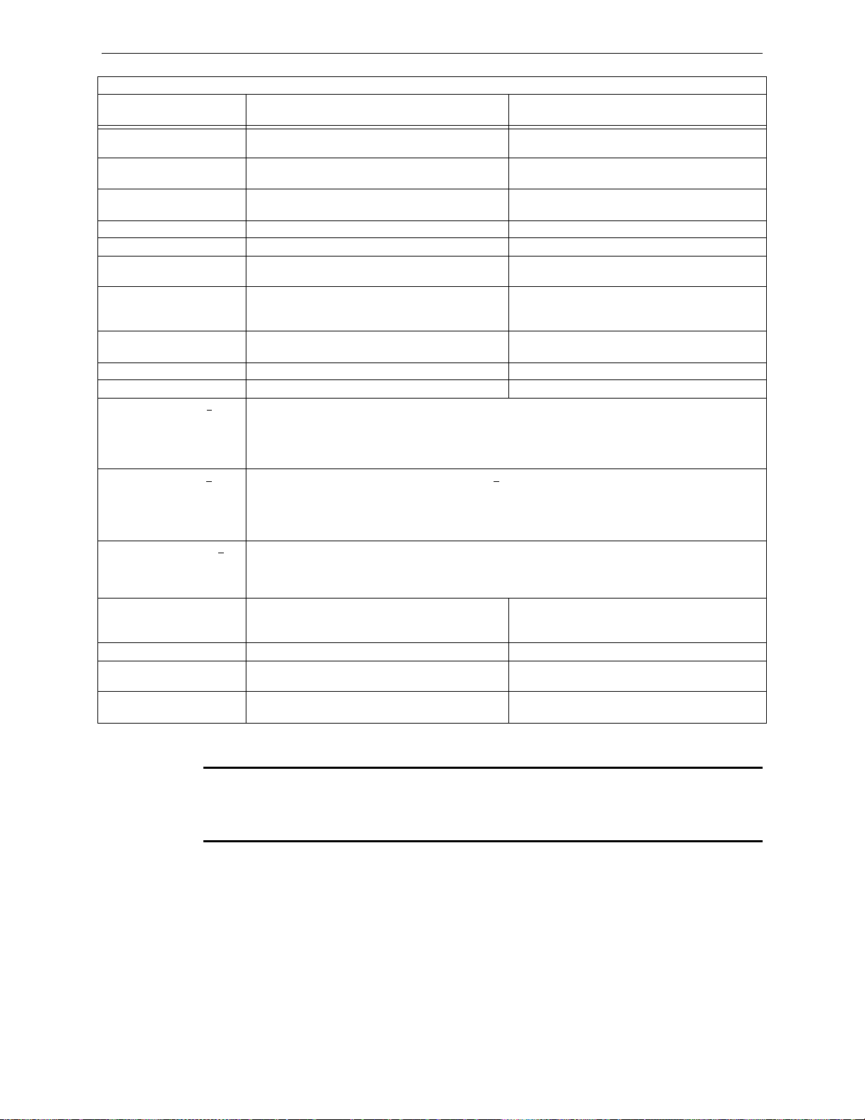
Point and System Troubles Lists System Troubles
SYSTEM TROUBLES
TROUBLE MESSAGE
TYPE
NETWORK FAIL PORT x Communication lost between NCM Port x and
NETWORK INCOMPATIBLE The brand of this panel is incompatible with this
NFPA 24HR REMINDER This message occurs every day at 11 am if any
NO DEV. INST ON L1 No devices are installed on the system. Install SLC and run autoprogram.
PANEL DOOR OPEN The panel door is open. Close door.
POWER SUPPLY COMM
FAIL
PROGRAM CORRUPTED T he database that houses the panel’s programming is
PROGRAM MODE
ACTIVATED
RELEASE DEV. DISABLE Rel easing devices have been disabled. Enable the devices.
SELF TEST FAILED Diagnostic test failed. Call Technical Services.
STYLE 6 POS. LOOP x There is an open circuit on the positive side of loop x. Style 6 and Style 7 are supervised methods of
STYLE 6 NEG. LOOP x There is an open circuit on the negative side of loop x. Style 6 and Style 7 are supervised methods of
STYLE 6 SHORT LOOP x Style 6 and Style 7 are supervised methods of communicating with addressable devices. If the control panel
SYS INITIALIZA TION The devices are initializing. No action is required, as the trouble will clear when
TERMINAL SUPERVISORY There is a communication error with the CRT-2. Check connections to the CRT-2 terminal.
UDACT NO ANSWER The UDACT i s not responding. Determine whether the UDACT is functional, and
UDACT TROUBLE The UDACT is in trouble. Determine if the UDACT is functional and wired
TROUBLE DESCRIPTION ACTION
corresponding node.
network.
troubles exist.
There has been a communication failure with the power
supply.
corrupt.
A user is currently accessing the panel’s programming
menus.
communicating with addressable devices. If the control panel detects a trouble (open), it will drive both ends of
the loop, maintaining communication in an unsupervised method. The latching trouble will display on the panel
as a Style 6 trouble until you correct the condition and press RESET. Style 7 configuration of the SLC r equires
the use of ISO-X modules.
communicating with addressable devices. If the control panel detects a trouble (open), it will drive both ends of
the loop, maintaining communication in an unsupervised method. The latching trouble will display on the panel
as a Style 6 trouble until you correct the condition and press RESET. Style 7 configuration of the SLC requires
the use of ISO-X modules.
detects a trouble (open or short), it will drive both ends of the loop, maintaining communication in an
unsupervised method. The latching trouble will display on the panel as a Style 6 trouble until you correct the
condition and press RESET. Style 7 configuration of the SLC requires the use of ISO-X modules.
Check wiring and verify the node is online.
Verify all nodes are branded for the same OEM.
Resolve any troubles on the system.
Service is required.
The database must be re-downloaded, or all
programming must be cleared and re-entere d .
Service is required.
No action is required / Exit the Programming mode.
initialization is completed. However, the devices will
not report off-normal events while this trouble exists.
connected and addressed prop erly.
correctly.
Table D.2 System Troubles
NOTE: A charger fail trouble can be charger or battery related. Batteries near the end of their
service life may not accept the periodic charge current required by UL 864 Ninth edition, and can
result in the panel displaying a charger fail. Batteries should be tested and replaced as necessary
before repairing or replacing the panel.
70 NFS-320/E/C, NFS-320SYS/E Operations Manual — P/N 52747:E1 06/16/2011
Page 71

Notes
NFS-320/E/C, NFS-320SYS/E Operations Manual — P/N 52747:E1 06/16/2011 71
Page 72

Index
A
Abort 49
Abort Active LED 12
Acknowledge/Scroll Display control key 12
Active Supervisory Signal 24–26
panel indication 24
response to 25
Type Codes 25
Alarm Verification Timer 32, 58
Alarm. See Fire Alarm 17
Analog Display 58
Annunciator Selections, read status 41
Auto Silence Timer 32
Automatic Test Operation 58
B
Battery Levels, read status 43
C
Caution
Disabling a zone disables all input and out-
put... 28
Coding
to view F8 selections 54
Coding, NAC 54
Control Keys 12
Control Panel Keys and Indicators, illustration 11
Control/Relay Module Trouble
panel indication 31
response to 32
Type Codes 30
Control/Relay Module, read status 37
Controls Active LED 11
Cooperative Multi-Detector, read status 37
Cross Zone 49
Cross Zone Programming illustration 51
CRT-2 and Read Status 62
Accessing 62
CRT-2 and Read Status. See Appendix C
D
Date Functions 52
Day/Night Sensitivity Operation 58
Delay Timer 49
Detector
fire alarm type codes 18, 21
Functions 58
Read Status 37
supervisory alarm type codes 26
Disabled Points 28
Discharge LED 12
Drill control key 14
F
Fire Alarm 17–18
LED 12
panel indication 17
response to a 17, 55
Fire Control Type Code, active point 29
H
Hidden History, read status and print 47
History, event and alarm, read status 44
Holiday Functions 52
to view selections 53
I
Increment Number key 14
ISO-X module 33, 70
L
Lamp Test control key 14
Latching Supervisory Type Code 25
Latching/non-latching type codes. See particular
type code for definition.
LED Control Operation 58
LEDs, table of 11
Local Control setting and control keys 13
LocM (Local Monitor) 60, 61
LocT (Local Terminal Mode) 60
M
Maintenance Alert 58
Manual Release 49
Monitor Module
fire alarm type codes 18, 21
non-alarm type codes 28
Read Status 37
security type codes 24
supervisory alarm type codes 26
trouble monitor type codes 29
N
NAC Trouble
panel indication 31
response to 32
Type Codes 30
NAC, read status 38
Non-Alarm Points 28
Non-Fire Point, active, panel indication 29
72 NFS-320/E/C, NFS-320SYS/E Operations Manual — P/N 52747:E1 06/16/2011
Page 73

Index O–W
Non-latching Supervisory Type Code 25
Normal Mode of Operation 16
O
Output Circuit Trouble 30–32
P
Partial Signal Silence 13
Point (Device) Troubles table 68
Point Disabled LED 12
Power LED 11
Pre-alarm LED 12
Pre-Alarm Warning 26
action level 27
alert level 27
panel indication 26
response to 27
Pre-Discharge LED 12
Presignal and Positive Alarm Sequence (PAS)
response to Presignal Delay Timer alarm
(no PAS)
response to Presignal Delay Timer alarm
(PAS selected)
to view selections 56
56
57
R
Read Status 34–47
to enter 34
to print 45
alarm history 46
event history 46
points 45
print hidden event and alarm history
47
print points 46
to view 35
annunciator selections 41
battery levels 43
detector information 36
devices, zones, system settings 35
event and alarm history 44
point or zone information 36
Releasing Zone (R0-R9) 40
releasing zone selections
software zones 39
Special Zone (F0-F9) 39
System Functions 40
total of installed devices 36
using a CRT. See Appendix C
Recall Last Entry key 14
Releasing Zone (R0-R9), read status 40
Releasing Zones (R0-R9) 49–51
Remote Terminal Access 60–??
RemT, Remote Terminal Mode 60, 61
S
Security Alarm 23
panel indication 23
response to a 23
Security LED 12
Sensitivity Adjust 58
Shortcuts to Operating Functions 10
Signal Silence control key 13
Signals Silenced LED 12
Silence Inhibit Timer 32, 33
Soak Timer 49
Software Zone (Z01-Z99), read status 39
Special Zone Operation 49–57
Special Zone, read status 39
Supervisory LED 12
Supplemental Documentation 9
System Functions, read status 40
System Normal Message 16
System Reset control key 13
System Timers 32
Alarm Verification Timer 32
Auto Silence Timer 32
Silence Inhibit Timer 32, 33
to view selections 32
System Trouble 21–23
panel indication 21
response to 22
System Trouble LED 12
System Troubles 69
T
Time Functions 52
to view selections 52
Timers. See System Timers 32
Transponder Points 30
Trouble Monitor 29
response to 30
trouble monitor type codes 29
Troubles
Point 68
System 69
Type Code Supervision 58
Type Codes
Fire Alarm 18
Non-alarm 28
Security 24
Supervisory 26
Trouble 29
W
Warning
When used for CO2 releasing applica-
tions... 16, 49
Waterflow Circuit operation 33
NFS-320/E/C, NFS-320SYS/E Operations Manual — P/N 52747:E1 06/16/2011 73
Page 74

X–X Index
X
XP6-C 30
XPC transponder points 30
74 NFS-320/E/C, NFS-320SYS/E Operations Manual — P/N 52747:E1 06/16/2011
Page 75

Manufacturer Warranties and Limitation of Liability
Manufacturer Warranties. Subject to the limitations set forth herein,
Manufacturer warrants that the Products manufactured by it in its
Northford, Connecticut facility and sold by it to its authorized
Distributors shall be free, under normal use and service, from defects
in material and workmanship for a period of thirty six months (36)
months from the date of manufacture (effective Jan. 1, 2009). The
Products manufactured and sold by Manufacturer are date stamped at
the time of production. Manufacturer does not warrant Products that
are not manufactured by it in its Northford, Connecticut facility but
assigns to its Distributor, to the extent possible, any warranty offered
by the manufacturer of such product. This warranty shall be void if a
Product is altered, serviced or repaired by anyone other than
Manufacturer or its authorized Distributors. This warranty shall also
be void if there is a failure to maintain the Products and the systems in
which they operate in proper working conditions.
MANUFACTURER MAKES NO FURTHER WARRANTIES, AND
DISCLAIMS ANY AND ALL OTHER WARRANTIES, EITHER
EXPRESSED OR IMPLIED, WITH RESPECT TO THE PRODUCTS,
TRADEMARKS, PROGRAMS AND SERVICES RENDERED BY
MANUFACTURER INCLUDING WITHOUT LIMITATION,
INFRINGEMENT, TITLE, MERCHANTABILITY, OR FITNESS FOR
ANY PA RTICULAR PURPOSE. MANUFACTURER SHALL NOT BE
LIABLE FOR ANY PERSONAL INJURY OR DEATH WHICH MAY
ARISE IN THE COURSE OF, OR AS A RESULT OF, PERSONAL,
COMMERCIAL OR INDUSTRIAL USES OF ITS PRODUCTS.
This document constitutes the only warranty made by Manufacturer
with respect to its products and replac es all previous warranties and is
the only warranty made by Manufacturer. No increase or alteration,
written or verbal, of the obligation of this warranty is authorized.
Manufacturer does not represent that its products will preven t any loss
by fire or otherwise.
Warranty Claims. Manufacturer shall replace or repair, at
Manufacturer's discretion, each part returned by its authorized
Distributor and acknowledged by Manufacturer to be defective,
provided that such part shall have been returned to Manufacturer with
all charges prepaid and the authorized Distributor has completed
Manufacturer's Return Material Authorization form. The replacement
part shall come from Manufacturer's stock and may be new or
refurbished. THE FOREGOING IS DISTRIBUTOR'S SOLE AND
EXCLUSIVE REMEDY IN THE EVENT OF A WARRANTY CLAIM.
Warn-HL-08-2009.fm
NFS-320/E/C, NFS-320SYS/E Operations Manual — P/N 52747:E1 06/16/2011 75
Page 76

World Headquarters
12 Clintonville Road
Northford, CT 06472-1610 USA
203-484-7161
fax 203-484-7118
www.notifier.com
 Loading...