

Page 1

Fire Alarm Control Panel
NFS-320/E/C
Installation Manual
Document 52745
7/1/14 Rev:
P/N 52745:M2 ECN 13-838
M2
Page 2

Fire Alarm & Emergency Communication System Limitations
While a life safety system may lower insurance rates, it is not a substitute for life and property insurance!
An automatic fire alarm system—typically made up of smoke
detectors, heat detectors, manual pull stations, audible warning
devices, and a fire alarm control panel (FACP) with remote notification capability—can provide early warning of a developing fire.
Such a system, however, does not assure protection against
property damage or loss of life resulting from a fire.
An emergency communication system—typically made up of
an automatic fire alarm system (as described above) and a life
safety communication system that may include an autonomous
control unit (ACU), local operating console (LOC), voice communication, and other various interoperable communication methods—can broadcast a mass notification message. Such a
system, however, does not assure protection against property
damage or loss of life resulting from a fire or life safety event.
The Manufacturer recommends that smoke and/or heat
detectors be located throughout a protected premises following
the recommendations of the current edition of the National Fire
Protection Association Standard 72 (NFPA 72), manufacturer's
recommendations, State and local codes, and the
recommendations contained in the Guide for Proper Use of
System Smoke Detectors, which is made available at no charge
to all installing dealers. This document can be found at http://
www.systemsensor.com/appguides/. A study by the Federal
Emergency Management Agency (an agency of the United
States government) indicated that smoke detectors may not go
off in as many as 35% of all fires. While fire alarm systems are
designed to provide early warning against fire, they do not
guarantee warning or protection against fire. A fire alarm system
may not provide timely or adequate warning, or simply may not
function, for a variety of reasons:
Smoke detectors may not sense fire where smoke cannot reach
the detectors such as in chimneys, in or behind walls, on roofs,
or on the other side of closed doors. Smoke detectors also may
not sense a fire on another level or floor of a building. A secondfloor detector, for example, may not sense a first-floor or basement fire.
Particles of combustion or “smoke” from a developing fire
may not reach the sensing chambers of smoke detectors
because:
• Barriers such as closed or partially closed doors, walls, chimneys, even wet or humid areas may inhibit particle or smoke
flow.
• Smoke particles may become “cold,” stratify, and not reach
the ceiling or upper walls where detectors are located.
• Smoke particles may be blown away from detectors by air
outlets, such as air conditioning vents.
• Smoke particles may be drawn into air returns before reaching the detector.
The amount of “smoke” present may be insufficient to alarm
smoke detectors. Smoke detectors are designed to alarm at various levels of smoke density. If such density levels are not created by a developing fire at the location of detectors, the
detectors will not go into alarm.
Smoke detectors, even when working properly, have sensing limitations. Detectors that have photoelectronic sensing chambers
tend to detect smoldering fires better than flaming fires, which
have little visible smoke. Detectors that have ionizing-type sensing chambers tend to detect fast-flaming fires better than smoldering fires. Because fires develop in different ways and are
often unpredictable in their growth, neither type of detector is
necessarily best and a given type of detector may not provide
adequate warning of a fire.
Smoke detectors cannot be expected to provide adequate warning of fires caused by arson, children playing with matches
(especially in bedrooms), smoking in bed, and violent explosions
(caused by escaping gas, improper storage of flammable materials, etc.).
Heat detectors do not sense particles of combustion and alarm
only when heat on their sensors increases at a predetermined
rate or reaches a predetermined level. Rate-of-rise heat detectors may be subject to reduced sensitivity over time. For this reason, the rate-of-rise feature of each detector should be tested at
least once per year by a qualified fire protection specialist. Heat
detectors are designed to protect property, not life.
IMPORTANT! Smoke detectors must be installed in the same
room as the control panel and in rooms used by the system for
the connection of alarm transmission wiring, communications,
signaling, and/or power. If detectors are not so located, a developing fire may damage the alarm system, compromising its ability to report a fire.
Audible warning devices such as bells, horns, strobes,
speakers and displays may not alert people if these devices
are located on the other side of closed or partly open doors or
are located on another floor of a building. Any warning device
may fail to alert people with a disability or those who have
recently consumed drugs, alcohol, or medication. Please note
that:
• An emergency communication system may take priority over
a fire alarm system in the event of a life safety emergency.
• Voice messaging systems must be designed to meet intelligibility requirements as defined by NFPA, local codes, and
Authorities Having Jurisdiction (AHJ).
• Language and instructional requirements must be clearly disseminated on any local displays.
• Strobes can, under certain circumstances, cause seizures in
people with conditions such as epilepsy.
• Studies have shown that certain people, even when they hear
a fire alarm signal, do not respond to or comprehend the
meaning of the signal. Audible devices, such as horns and
bells, can have different tonal patterns and frequencies. It is
the property owner's responsibility to conduct fire drills and
other training exercises to make people aware of fire alarm
signals and instruct them on the proper reaction to alarm signals.
• In rare instances, the sounding of a warning device can cause
temporary or permanent hearing loss.
A life safety system will not operate without any electrical
power. If AC power fails, the system will operate from standby
batteries only for a specified time and only if the batteries have
been properly maintained and replaced regularly.
Equipment used in the system may not be technically compatible with the control panel. It is essential to use only equipment
listed for service with your control panel.
Telephone lines needed to transmit alarm signals from a premises to a central monitoring station may be out of service or temporarily disabled. For added protection against telephone line
failure, backup radio transmission systems are recommended.
The most common cause of life safety system malfunction is
inadequate maintenance. To keep the entire life safety system in
excellent working order, ongoing maintenance is required per the
manufacturer's recommendations, and UL and NFPA standards. At a minimum, the requirements of NFPA 72 shall be followed. Environments with large amounts of dust, dirt, or high air
velocity require more frequent maintenance. A maintenance
agreement should be arranged through the local manufacturer's
representative. Maintenance should be scheduled monthly or as
required by National and/or local fire codes and should be performed by authorized professional life safety system installers
only. Adequate written records of all inspections should be kept.
Limit-D-1-2013
2 NFS-320/E/C Installation Manual — P/N 52745:M2 7/1/14
Page 3

Installation Precautions
Adherence to the following will aid in problem-free installation with long-term reliability:
WARNING - Several different sources of power can be
connected to the fire alarm control panel. Disconnect all
sources of power before servicing. Control unit and associated equipment may be damaged by removing and/or inserting cards, modules, or interconnecting cables while the unit is
energized. Do not attempt to install, service, or operate this
unit until manuals are read and understood.
CAUTION - System Re-acceptance Test after Software
Changes: To ensure proper system operation, this product
must be tested in accordance with NFPA 72 after any programming operation or change in site-specific software. Reacceptance testing is required after any change, addition or
deletion of system components, or after any modification,
repair or adjustment to system hardware or wiring. All components, circuits, system operations, or software functions known
to be affected by a change must be 100% tested. In addition,
to ensure that other operations are not inadvertently affected,
at least 10% of initiating devices that are not directly affected
by the change, up to a maximum of 50 devices, must also be
tested and proper system operation verified.
This system meets NFPA requirements for operation at 0-49º
C/32-120º F and at a relative humidity 93% ± 2% RH (noncondensing) at 32°C ± 2°C (90°F ± 3°F). However, the useful
life of the system's standby batteries and the electronic components may be adversely affected by extreme temperature
ranges and humidity. Therefore, it is recommended that this
system and its peripherals be installed in an environment with
a normal room temperature of 15-27º C/60-80º F.
Verify that wire sizes are adequate for all initiating and indicating device loops. Most devices cannot tolerate more than a
10% I.R. drop from the specified device voltage.
Like all solid state electronic devices, this system may
operate erratically or can be damaged when subjected to lightning induced transients. Although no system is completely
immune from lightning transients and interference, proper
grounding will reduce susceptibility. Overhead or outside aerial
wiring is not recommended, due to an increased susceptibility
to nearby lightning strikes. Consult with the Technical Services Department if any problems are anticipated or encountered.
Disconnect AC power and batteries prior to removing or
inserting circuit boards. Failure to do so can damage circuits.
Remove all electronic assemblies prior to any drilling, filing,
reaming, or punching of the enclosure. When possible, make
all cable entries from the sides or rear. Before making modifications, verify that they will not interfere with battery, transformer, or printed circuit board location.
Do not tighten screw terminals more than 9 in-lbs. Overtightening may damage threads, resulting in reduced terminal
contact pressure and difficulty with screw terminal removal.
This system contains static-sensitive components.
Always ground yourself with a proper wrist strap before handling any circuits so that static charges are removed from the
body. Use static suppressive packaging to protect electronic
assemblies removed from the unit.
Follow the instructions in the installation, operating, and programming manuals. These instructions must be followed to
avoid damage to the control panel and associated equipment.
FACP operation and reliability depend upon proper installation.
Precau-D1-9-2005
FCC Warning
WARNING: This equipment generates, uses, and can
radiate radio frequency energy and if not installed and
used in accordance with the instruction manual may
cause interference to radio communications. It has been
tested and found to comply with the limits for class A
computing devices pursuant to Subpart B of Part 15 of
FCC Rules, which is designed to provide reasonable
protection against such interference when devices are
operated in a commercial environment. Operation of this
equipment in a residential area is likely to cause interference, in which case the user will be required to correct
the interference at his or her own expense.
Canadian Requirements
This digital apparatus does not exceed the Class A limits
for radiation noise emissions from digital apparatus set
out in the Radio Interference Regulations of the Canadian Department of Communications.
Le present appareil numerique n'emet pas de bruits radioelectriques depassant les limites applicables aux appareils numeriques de la classe A prescrites dans le
Reglement sur le brouillage radioelectrique edicte par le
ministere des Communications du Canada.
HARSH™, NIS™, and NOTI•FIRE•NET™ are all trademarks; and Acclimate® Plus, FlashScan®, NION®, NOTIFIER®, ONYX®, ONYXWorks®, UniNet®,
VeriF ire® , and VIEW® are all registered trademarks of Honeywell International Inc. Echelon® is a registered trademark and LonWorks™ is a trademark of
Echelon Corporation. ARCNET® is a registered trademark of Datapoint Corporation. Microsoft® and Windows® are registered trademarks of the Microsoft
Corporation.
©2014 by Honeywell International Inc. All rights reserved. Unauthorized use of this document is strictly prohibited.
NFS-320/E/C Installation Manual — P/N 52745:M2 7/1/14 3
Page 4

Software Downloads
In order to supply the latest features and functionality in fire alarm and life safety technology to our customers, we make
frequent upgrades to the embedded software in our products. To ensure that you are installing and programming the latest
features, we strongly recommend that you download the most current version of software for each product prior to
commissioning any system. Contact Technical Support with any questions about software and the appropriate version for a
specific application.
Documentation Feedback
Your feedback helps us keep our documentation up-to-date and accurate. If you have any comments or suggestions about our
online Help or printed manuals, you can email us.
Please include the following information:
•Product name and version number (if applicable)
•Printed manual or online Help
•Topic Title (for online Help)
•Page number (for printed manual)
•Brief description of content you think should be improved or corrected
•Your suggestion for how to correct/improve documentation
Send email messages to:
Please note this email address is for documentation feedback only. If you have any technical issues, please contact Technical
Services.
4 NFS-320/E/C Installation Manual — P/N 52745:M2 7/1/14
Page 5

Table of Contents
Section 1: About This Manual..................................................................................................7
1.1: Standards and Other Documents....................................................................................................................7
1.2: UL 864 Compliance.......................................................................................................................................8
1.2.1: Products Subject to AHJ Approval......................................................................................................8
1.3: Related Documents........................................................................................................................................8
1.4: Cautions and Warnings ..................................................................................................................................9
1.4.1: Typographic Conventions....................................................................................................................9
Section 2: System Overview.................................................................................................. 10
2.1: System Description......................................................................................................................................10
2.1.1: Standard Features ..............................................................................................................................10
2.1.2: Options ..............................................................................................................................................11
2.1.3: System Limitations............................................................................................................................11
2.2: System Components ....................................................................................................................................11
2.2.1: Standard Equipment ..........................................................................................................................11
2.2.2: Control Panel Circuit Board .............................................................................................................11
2.2.3: Main Power Supply CPS-24/E ..........................................................................................................12
2.2.4: Circuit Board Components ................................................................................................................13
2.2.5: System Cabinet..................................................................................................................................15
2.3: Compatible Equipment ...............................................................................................................................16
Section 3: Installation.............................................................................................................18
3.1: Preparing for Installation .............................................................................................................................18
3.1.1: Standards and Codes..........................................................................................................................18
3.2: Installation Checklist ...................................................................................................................................19
3.3: Mounting a Cabinet .....................................................................................................................................20
3.4: Installing Option Boards..............................................................................................................................20
3.5: Connecting the Power Cables......................................................................................................................22
3.5.1: Overview ...........................................................................................................................................22
3.5.2: Connecting the Control Panel to AC Power......................................................................................23
3.5.3: Checking AC Power ..........................................................................................................................23
3.5.4: Installing and Connecting the Batteries ............................................................................................24
3.5.5: External DC Power Output Connections...........................................................................................24
3.5.6: Accessories DC Power Output Connections .....................................................................................25
3.6: NAC Connections and Releasing Circuits...................................................................................................26
3.6.1: Stat-X Devices...................................................................................................................................27
3.7: Output Relay Connections...........................................................................................................................27
3.8: Backup-Alarm Switches .............................................................................................................................28
3.9: UL Power-limited Wiring Requirements.....................................................................................................29
3.9.1: Labeling Modules and Circuits..........................................................................................................30
3.10: Installing EIA-485 Devices .......................................................................................................................30
3.11: Installing Remote Printers and/or CRT......................................................................................................30
3.11.1: Custom Cable Fabrication ...............................................................................................................30
3.11.2: Installing and Configuring the PRN Series Printer .........................................................................31
3.11.3: Installing and Configuring a CRT-2................................................................................................32
3.11.4: Connecting Multiple Printers, CRTs, or CRT/PRN Combination ..................................................33
3.12: Wiring a Signaling Line Circuit (SLC)......................................................................................................34
3.13: Connecting a PC for Off-Line Programming ............................................................................................35
Section 4: Applications ..........................................................................................................36
4.1: Overview......................................................................................................................................................36
4.2: Devices Requiring External Power Supervision..........................................................................................36
4.3: NFPA 72 Central or Remote Station Fire Alarm System (Protected Premises Unit)..................................37
4.4: Central Station Fire Alarm System Canadian Requirements.......................................................................39
4.5: NFPA 72 Proprietary Fire Alarm Systems...................................................................................................40
NFS-320/E/C Installation Manual — P/N 52745:M2 7/1/14 5
Page 6

Table of Contents
4.6: Fire/Security Applications ..........................................................................................................................40
4.6.1: General Operation..............................................................................................................................40
4.6.2: Installing a Security Tamper Switch..................................................................................................41
4.6.3: Receiving Unit ...................................................................................................................................41
4.6.4: Programming .....................................................................................................................................41
4.6.5: Wiring for Proprietary Security Alarm Applications ........................................................................42
4.7: Releasing Applications ................................................................................................................................43
4.7.1: Overview............................................................................................................................................43
4.7.2: Programming .....................................................................................................................................43
4.7.3: Wiring ................................................................................................................................................43
4.7.4: Connecting a Releasing Device to the Control Panel ........................................................................44
4.7.5: Connecting a Releasing Device to the FCM-1 Module.....................................................................46
4.7.6: Connecting a Releasing Device to the FCM-1-REL .........................................................................47
4.7.7: Connecting an NBG-12LRA Agent Release-Abort Station ..............................................................48
Section 5: Testing the System .............................................................................................. 50
5.1: Acceptance Test ...........................................................................................................................................50
5.2: Periodic Testing and Service........................................................................................................................50
5.3: Operational Checks......................................................................................................................................50
5.4: Battery Checks and Maintenance.................................................................................................................51
Appendix A: Power Supply Calculations ............................................................................. 52
A.1: Calculating AC Branch Circuit Current......................................................................................................52
A.2: Calculating the System Current Draws ......................................................................................................52
A.2.1: Calculating the Maximum Secondary Power Fire Alarm Current Draw..........................................55
A.3: Calculating the Battery Requirements ........................................................................................................56
A.3.1: Calculating the Battery Capacity ......................................................................................................56
A.3.2: Calculating the Battery Size .............................................................................................................57
Appendix B: Electrical Specifications ..................................................................................58
B.1: Electrical Specifications..............................................................................................................................58
B.2: Wire Requirements......................................................................................................................................60
Index ........................................................................................................................................ 62
6 NFS-320/E/C Installation Manual — P/N 52745:M2 7/1/14
Page 7

Section 1: About This Manual
1.1 Standards and Other Documents
This Fire Alarm Control Panel complies with the following NFPA standards:
•NFPA 12 CO
• NFPA 12A Halon 1301 Extinguishing Systems
• NFPA 13 Sprinkler Systems
• NFPA 15 Water Spray Systems
• NFPA 16 Foam/Water Deluge and Foam/Water Spray Systems
• NFPA 17 Dry Chemical Extinguishing Systems
• NFPA 17A Wet Chemical Extinguishing Systems
• NFPA 72 Central Station Fire Alarm Systems (Automatic, Manual and Waterflow) Protected
Premises Unit (requires Notifier UDACT/UDACT-2).
• NFPA 72 Local (Automatic, Manual, Waterflow and Sprinkler Supervisory) Fire Alarm
Systems.
• NFPA 72 Auxiliary (Automatic, Manual and Waterflow) Fire Alarm Systems (requires TM-4).
• NFPA 72 Remote Station (Automatic, Manual and Waterflow) Fire Alarm Systems
• NFPA 72 Proprietary (Automatic, Manual and Waterflow) Fire Alarm Systems (Protected
Premises Unit).
• NFPA 2001 Clean Agent Fire Extinguishing Systems
The installer should be familiar with the following documents and standards:
• NFPA 72 Initiating Devices for Fire Alarm Systems
• NFPA 72 Inspection, Testing and Maintenance for Fire Alarm Systems
• NFPA 72 Notification Appliances for Fire Alarm Systems
Extinguishing Systems
2
Underwriters Laboratories
• UL 38 Manually Actuated Signaling Boxes
• UL 217 Smoke Detectors, Single and Multiple Station
• UL 228 Door Closers - Holders for Fire Protective Signaling Systems
• UL 268 Smoke Detectors for Fire Protective Signaling Systems
• UL 268A Smoke Detectors for Duct Applications
• UL 346 Waterflow Indicators for Fire Protective Signaling Systems
• UL 464 Audible Signaling Appliances
• UL 521 Heat Detectors for Fire Protective Signaling Systems
• UL 864 Standard for Control Units for Fire Protective Signaling Systems
• UL 1481 Power Supplies for Fire Protective Signaling Systems
• UL 1971 Visual Signaling Appliances
• UL 1076 Proprietary Burglar Alarm Systems
• UL 2017 Standard for General-Purpose Signaling Devices and Systems
• UL 2572 Standard for Mass Notification Systems
• UL 60950 Safety of Information Technology Equipment
Underwriters Laboratories of Canada (ULC)
• Standard CAN/ULC-S527-M99
• CAN/ULC-S524-M91 Standard for the Installation of Fire Alarm Systems
Other
• EIA-485 and EIA-232 Serial Interface Standards
• NEC Article 300 Wiring Methods
• NEC Article 760 Fire Protective Signaling Systems
• Applicable Local and State Building Codes
• Requirements of the Local Authority Having Jurisdiction
• C22.1-98 The Canadian Electrical Code, Part 1
NFS-320/E/C Installation Manual — P/N 52745:M2 7/1/14 7
Page 8

About This Manual UL 864 Compliance
1.2 UL 864 Compliance
1.2.1 Products Subject to AHJ Approval
This product has been certified to comply with the requirements in the Standard for Control Units
and Accessories for Fire Alarm Systems, UL 864 9th Edition.
The following products have not received UL 864 9th Edition certification and may only be used in
retrofit applications. Operation of the NFS-320/E/C with products not tested for UL 864 9th Edition
has not been evaluated and may not comply with NFPA 72 and/or the latest edition of UL 864.
These applications will require the approval of the local Authority Having Jurisdiction (AHJ).
• For a complete list of all peripherals that can be used with this fire alarm control panel (FACP),
and which of those peripherals have not received UL 864, 9th Edition certification and may
only be used in retrofit applications, see Section 2.3, “Compatible Equipment”, on page 16.
1.3 Related Documents
Table 1.1 below provides a list of documents referenced in this manual, as well as documents for
selected other compatible devices. The document series chart (DOC-NOT) provides the current
document revision. A copy of this document is included in every shipment.
Compatible Conventional Devices (Non-addressable) Document Number
Device Compatibility Document 15378
Fire Alarm Control Panel (FACP) and Main Power Supply Installation Document Number
NFS-320/E/C Installation, Operations, and Programming Manuals
NFS-320C Canadian Applications Addendum
SLC Wiring Manual 51253
Note: For individual SLC Devices, refer to the SLC Wiring Manual
Off-line Programming Utility Document Number
VeriFire® Tools CD help file VERIFIRE-TCD
Power Supplies, Auxiliary Power Supplies & Battery Chargers Document Number
ACPS-2406 Installation Manual 51304
ACPS-610 Instruction Manual 53018
APS-6R Instruction Manual 50702
APS2-6R Instruction Manual 53232
CHG-120 Battery Charger Manual 50641
FCPS-24S6/FCPS-24S8 Field Charger/Power Supply Manual 51977
Networking Document Number
52745, 52746, 52747
52745CDN
High-Speed Network Communication Module 54014
High-Speed Noti•Fire•Net Instruction Manual 54013
Noti•Fire•Net Manual, Network Version 5.0 & Higher 51584
ONYXWorks™ Workstation Hardware & Software Application: Installation and Operation Manual 52342
ONYXWorks™ NFN Gateway (PC Platform) Installation & Operation Manual 52307
Table 1.1 Reference Documentation (1 of 2)
8 NFS-320/E/C Installation Manual — P/N 52745:M2 7/1/14
Page 9
Cautions and Warnings About This Manual
!
!
ONYXWorks™ NFN Gateway (Embedded Platform) Installation & Operation Manual 52306
NCM-W/F Installation Document 51533
NCS ONYX® Network Control Station Manual, Network Version 4.0 & Higher 51658
NCA-2 Network Control Annunciator Manual 52482
NCA Network Control Annunciator Manual 51482
System Components Document Number
Annunciator Control System Manual 15842
ACM-8R Annunciator Control Module Manual 15342
FDU-80 Remote Annunciator Manual 51264
LCD-80 Liquid Crystal Display Annunciator 15037
LCD2-80 Liquid Crystal Display Annunciator 53242
LDM Series Lamp Driver Annunciator Manual 15885
SCS Smoke Control Manual (Smoke and HVAC Control Station) 15712
DPI-232 Direct Panel Interface Manual 51499
TM-4 Installation Document (Reverse Polarity Transmitter) 51490
UDACT Manual (Universal Digital Alarm Communicator/Transmitter) 50050
UDACT-2 Manual (Universal Digital Alarm Communicator/Transmitter) 54089
FireVoice-25/50 & FireVoice-25/50ZS Manual 52290
FirstCommand Emergency Communication System LS10001-001-NF-E
RA100Z Remote LED Annunciator Installation Document I56-0508
FSA-8000 Intelligent Aspiration Sensing Technology Document I56-3903
FWSG Wireless Manual LS10036-000NF-E
Table 1.1 Reference Documentation (2 of 2)
1.4 Cautions and Warnings
This manual contains cautions and warnings to alert the reader as follows:
CAUTION:
Information about procedures that could cause programming errors, runtime errors, or equipment
damage.
WARNING:
Indicates information about procedures that could cause irreversible damage to the control panel,
irreversible loss of programming data or personal injury.
1.4.1 Typographic Conventions
NOTE: The term NFS-320 is used in this manual to refer to the NFS-320, and the NFS-320E
and the NFS-320C, unless otherwise noted.
NFS-320/E/C Installation Manual — P/N 52745:M2 7/1/14 9
Page 10

Section 2: System Overview
2.1 System Description
The NFS-320/E/C control panel is a modular, intelligent fire alarm control panel (FACP) with an
extensive list of powerful features. The control panel uses the CPS-24/E integral power supply with
battery charger. This is mounted in its cabinet to create a complete fire alarm control system. The
panel supports FlashScan® and CLIP mode; the board provides an integral signaling line circuit
(SLC) that can support up to 318 addressable points (159 detectors and 159 monitor/control
modules). The panel is networkable, and can be monitored across a network by other networked
panels.
Modular devices mount in the cabinet or in auxiliary backboxes to provide additional circuits. This
system is available in either a 120 VAC or 240 VAC configuration. Cabinetry can be ordered in
black or in red. The NFS-320/E/C chassis is removable, allowing work to be done outside the
cabinet.
2.1.1 Standard Features
• Uses Notifier’s VIEW® early warning fire detection and the FlashScan® or Classic Loop
Interface Protocol (CLIP) families of detectors and modules
• Integral power supply with battery charger
• Four standard Notification Appliance Circuits (NAC), Class A or B
• Alarm, Trouble, Supervisory and Security relays
• Support for 32 annunciator addresses, with 10 special annunciator groups
• Supports Style 4, Style 6, Style 7 SLC loops
• Releasing service using on-board NACs or FCM-1 modules
• Logic Equations
• Display scroll selection
• Alarm verification supervisory indication (NYC)
• Supervisory duct detectors
• Supports ONYX® Intelligent Sensing algorithms
• Network operation
• Battery charger supports 18 to 200 amp hour sealed lead-acid batteries
• EIA-485 connections for wiring ACS annunciators (including LDM custom graphic
annunciators), TM-4 transmitter
• EIA-232 connections for printer, CRT, printer/CRT, or network operation
• VeriFire Tools® off-line programming utility
• Autoprogram feature for faster device programming
• The control panel provides 6 amps of usable output power in an alarm condition; it provides
3 amps of usable output power in normal or continuous operating conditions
• Diagnostic LEDs and switches
• Ground fault detection (0 ohm impedance)
• Battery and battery-charger supervision, voltage-monitoring, and current-monitoring
• Disconnect of deeply-discharged battery (low battery disconnect)
• Programmable for strobe synchronization
• QWERTY silicone-rubber keypad with a 2x40 LCD display and eight indicator LEDs
• Mass Notification System compatible
10 NFS-320/E/C Installation Manual — P/N 52745:M2 7/1/14
Page 11

System Components System Overview
2.1.2 Options
Refer to Section 2.2 “System Components” for descriptions of the various optional modules.
• Optional devices include: Wire and Fiber
versions of the NCM or HS-NCM
connection to the Noti•Fire•Net and HighSpeed Noti•Fire•Net, UDACT/UDACT-2
Universal Digital Alarm
2.1.3 System Limitations
System expansion must take into consideration the following:
1. The physical limitations of the cabinet configuration.
2. The electrical limitations of the system power supply.
3. The capacity of the secondary power source (standby batteries). (Note that batteries larger than
26 AH will require a separate battery backbox.)
2.2 System Components
2.2.1 Standard Equipment
The standard, factory-assembled NFS-320/E/C system includes the following components:
• The control panel with integral power supply, and cabinet. NFS-320 (120V operation) or NFS320E (220-240V operation), and CPS-24/E. NFS-320/E is the “control panel” itself and the
heart of the system; it ships with a grounding cable, battery interconnect cables, and document
kit. CPS-24/E mounts directly on the control panel. The system ships pre-installed in its
cabinet.
Communicator/Transmitter, and ACM-8R
remote relay module to increase point
capacity.
• Optional annunciators connected through
the EIA-485 interface allow remote
system monitoring.
NOTE: The CPS-24/E is an integral part of the NFS-320 and is not available separately.
• A primary display KDM-R2 keypad/display.
Batteries are ordered separately; refer to Appendix A.3 “Calculating the Battery Requirements” for
system current-draw calculations.
Up to two option boards can be installed within the FACP’s cabinet; additional optional peripherals
can be mounted in auxiliary backboxes. Refer to Section 2.3, “Compatible Equipment” for
equipment listed for use with this FACP.
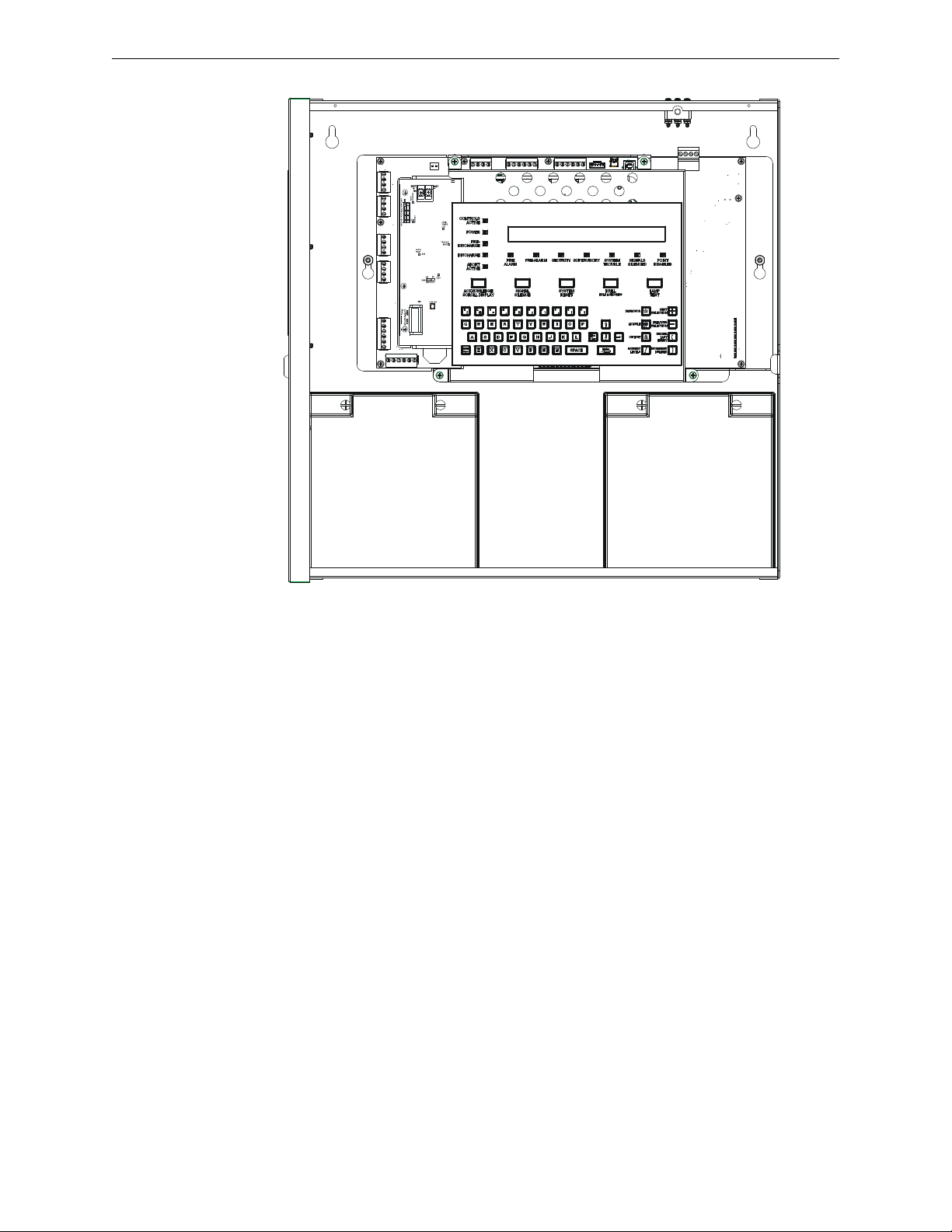
2.2.2 Control Panel Circuit Board
The control panel electronics are contained in NFS-320 and its built-in power supply. The printed
circuit board incorporates a signaling line circuit (SLC) and the central processing unit; the power
supply has an integral battery charger. A keypad/display unit is installed over the power supply as
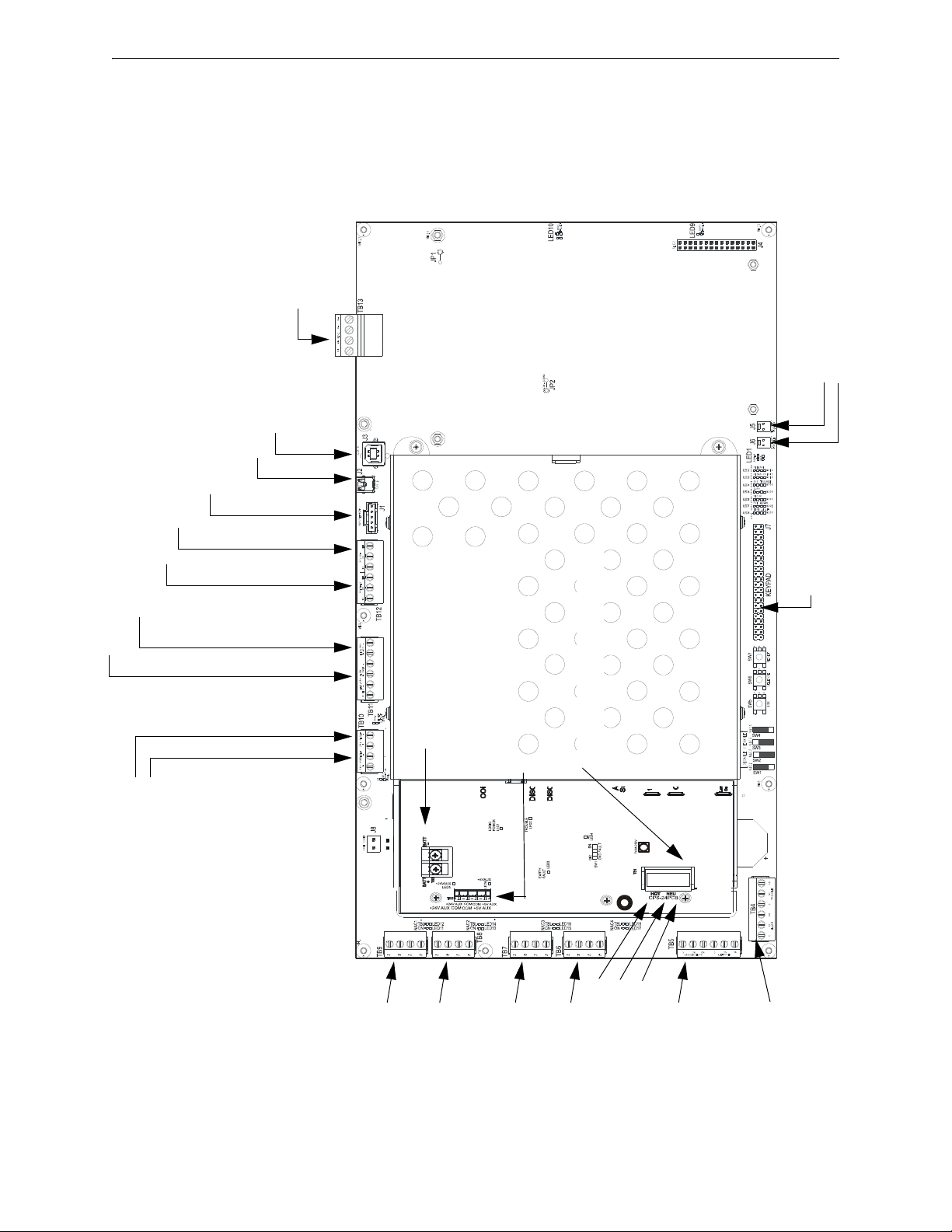
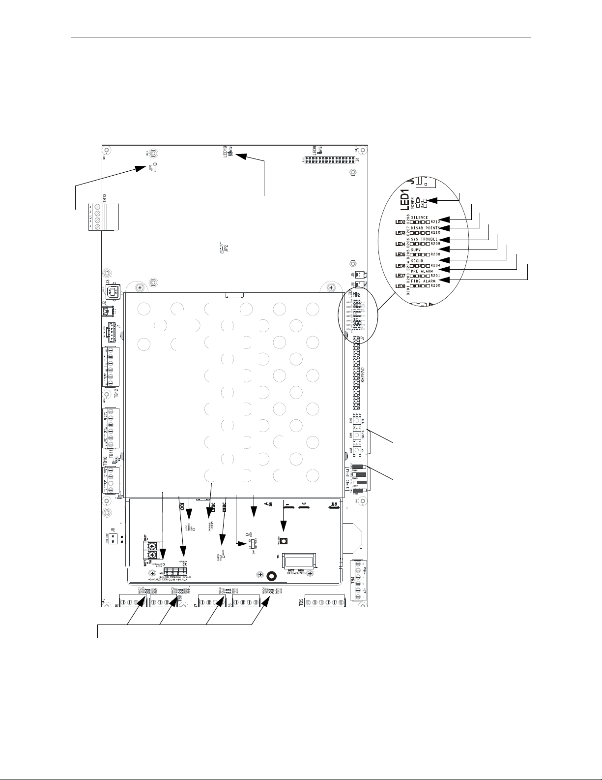
shown Figure 2.1. Wiring is shown in Figure 2.2, “NFS-320 and Power-Supply: Wiring
Connections” and Figure 2.3, “NFS-320 and Power-Supply: Jumpers, LEDs and Switches”.
NFS-320/E/C Installation Manual — P/N 52745:M2 7/1/14 11
Page 12
System Overview System Components
320door_open.wmf
Figure 2.1 NFS-320/E/C System, Shown
with Door Open
2.2.3 Main Power Supply CPS-24/E
The main power supply is an integral part of the NFS-320/E/C and mounts directly over the control
panel’s circuit board. It provides a total of 3.9 A (7.4 A in alarm) and contains an integral battery
charger. This can be used for many functions including:
• Powering the NFS-320/E/C
• Powering a variety of UL-listed 24 VDC
notification appliances from four built-in
NAC outputs
• Providing up to 1.25 A of resettable power
for four-wire smoke detectors
See Figure 2.2, “NFS-320 and Power-Supply: Wiring Connections” and Figure 2.3, “NFS-320 and
Power-Supply: Jumpers, LEDs and Switches” for details.
• Providing up to 1.25 A of non-resettable
power for external devices such as the
TM-4 Transmitter Module
• Providing auxiliary 24 VDC power @ 0.5
A and 5 VDC power @ 0.15 A
• Fuse: 8 amps, 250 V, 5 x 20 mm, Fast
Acting, ceramic, p/n 12117
12 NFS-320/E/C Installation Manual — P/N 52745:M2 7/1/14
Page 13
System Components System Overview
TB13 - SLC Loop #1
(supervised, power-
limited)
(Figure 3.18)
TB11 - EIA-485 ACS Mode Connection (supervised)
TB11 - EIA-485 Terminal Mode Connection (supervised)
(Figure 3.14 on page 30)
TB10 - DC Power
(24 VDC power-limited)
Resettable
Non-resettable
(See Figure 3.6 on page 24)
TB12 - EIA-232 Printer Connection (Figure 3.15 on page 31)
TB12 - EIA-232 PC/Terminal Connection (CRT)
(Figure 3.16 on page 32)
J1 - Network/Service Connection (NUP)
(power-limited, supervised)
J2 - USB A VeriFire Tools Connection
J3 - USB B VeriFire Tools Connection
TB8 - NAC#2
All NAC Circuits: power-
limited, supervised
(Figure 3.9 on page 26)
TB9 - NAC#1
TB7 - NAC#3
TB6 - NAC#4
Output Relays - power-limited only if connected to a power-limited
source. (See Figure 3.11 on page 27 for details.)
TB5 -
Supervisory Relay
Security Relay
TB4 -
Alarm Relay
Trouble Relay
J5 - Security Tamper Switch
J6 - Auxiliary Trouble Input
J7 - KDM-R2
Connection
CPU320-KAPS-
Figure 2.2 NFS-320 and Power-Supply: Wiring Connections
TB3 - Battery Connection
(over-current protected, non-power-limited)
TB1 - AC Power Connection (non-
power-limited)
Hot
Neutral
Earth
Ground
(+) (-)
TB2 - Secondary Power Auxiliary Outputs
(power-limited)
2.2.4 Circuit Board Components
The following three figures illustrate the location of the various connections, switches, jumpers and
LEDs on the NFS-320 and its power supply. Figure 2.2 shows wiring connections; Figure 2.3
shows jumpers, LEDs and switches. See Section 3 “Installation” for larger images and more details.
(Larger images are referenced on these drawings.)
NFS-320/E/C Installation Manual — P/N 52745:M2 7/1/14 13
Page 14
NAC
LEDs
Disable - Enable Switches
for Backup Alarm
(Figure 3.12 on page 28)
LED10 – SLC Loop
Ground Fault LED
LED5 - Supervisory LED
LED7 - Pre-Alarm LED
LED6 - Security LED
LED3 - Point Disabled LED
LED2 - Signals Silenced LED
LED4 - System Trouble LED
LED8 - Fire Alarm LED
LED1 - Power-on LED (AC or battery)
System Switches - ‘No
Keyboard Operation’
SW5 - Acknowledge
SW6 - Silence
SW7 - Reset
CPU320-KAPS-291809.wmf, CPU2-640-
JP1 - SLC Ground
Fault Jumper
SW1 - Ground Fault Detection Enable/Disable
LED3 - Earth Fault LED (general board ground fault)
Figure 2.3 NFS-320 and Power-Supply: Jumpers, LEDs and Switches
LED5 - +24V Aux LED
LED6 - +5V Aux LED
LED6 - +5V Aux LEDLED1 - Logic Power LED
LED2 - Trouble LED
LED4 - AC Power LED
F4- AC Fuse
System Overview System Components
14 NFS-320/E/C Installation Manual — P/N 52745:M2 7/1/14
Page 15

System Components System Overview
2.2.5 System Cabinet
The control panel is factory installed in its backbox. The lockable door is hinged on the left and
opens a full 180 degrees. Mounting methods include surface-mounting or semi-flush mounting on a
wall between 16 inch (40.64 cm) on-center studs. A trim ring option is available for semi-flush
mounting.
External measurements:
• Backbox: 18.12 in. (46.025 cm) width;
18.12 in. (46.025 cm) height;
5.81 in. (14.76 cm) depth.
When using trim ring TR-320, mount backbox with at least 1 inch (2.54 cm) between wall surface
and front of backbox, to allow door to open fully past the trim ring. The TR-320 molding width is
0.905 in. (2.299 cm).
Additional Options
The NFS-320/E/C control panel provides space for one or two additional option boards to be
installed, as shown in Figure 3.3 on page 21. The NFS-320C fulfills ULC annunciation
requirements; see NFS-320C Canadian Applications Addendum for details. A variety of compatible
annunciators are available with their own backboxes; see Section 2.3, “Compatible Equipment”.
• Door: 18.187 in. (46.195 cm) width;
18.40 in. (46.736 cm) height;
0.75 in. (1.905 cm) depth.
NFS-320/E/C Installation Manual — P/N 52745:M2 7/1/14 15
Page 16

System Overview Compatible Equipment
!
Continued on next page...
2.3 Compatible Equipment
These are the most common devices at time of publishing; the most complete list of compatible
intelligent SLC loop devices is provided in the SLC Wiring Manual; for conventional nonaddressable equipment see the Device Compatibility Document. These devices are UL and ULC
listed unless marked otherwise (in parentheses next to the product). Other control panels and their
equipment can also be connected in a network, via Noti•Fire•Net version 5.0 or the High-Speed
Noti•Fire•Net; refer to the Noti•Fire•Net Version 5.0 & Higher Installation Manual or High-Speed
Noti•Fire•Net Installation Manual for details. For products documented separately, see Section 1.3
“Related Documents”.
WARNING: UL 9th Edition Compliance
This product has been certified to comply with the requirements in the Standard for Control Units and
Accessories for Fire Alarm Systems, UL 864 9th Edition. Operation of the NFS-320/E/C with
products not tested for UL 864 9th Edition has not been evaluated and may not comply with NFPA 72
and/or the latest edition of UL 864. These applications will require the approval of the local Authority
Having Jurisdiction (AHJ).
Peripheral devices in the second list were listed under UL 8th Edition and may only be used in retrofit
applications (see Section 1.2, “UL 864 Compliance”, on page 8).
Notifier Compatible Equipment
NOTE: Products marked with a checkmark “” have not received UL 864 9th Edition
certification and may only be used in retrofit applications (see Section 1.2, “UL 864 Compliance”,
on page 8)
NOTE: The wireless option is not suitable for ULC.
Electronic Equipment
A77-716B End-of-Line Resistor Assembly
Acclimate Plus™ FAPT-751, FAPT-851 Combination
Photoelectric/Heat Detector
ACM-24AT Annunciator Control Module
ACM-48A Annunciator Control Module
ACM-8R Annunciator Control Module
ACPS-610 Addressable Charger/Power Supply
AEM-24AT Annunciator Expander Module
AEM-48A Annunciator Expander Module
AKS-1B Annunciator Key Switch
APS2-6R Auxiliary Power Supply
B200S Addressable sounder base
B200SR Sounder base
B501 Intelligent base
B501BH Sounder base
B501BH-2 Sounder base, steady tone
B501BHT-2 Sounder base, temporal tone
B710LP/B210LP Intelligent detector base
BAT-12120 Battery 12-volt, 12 amp-hour
BAT-12180 Battery 12-volt, 18 amp-hour
BAT-12250 Battery 12-volt, 25 amp-hour
BAT-12260 Battery 12-volt, 26 amp-hour
BAT-12550 Battery 12-volt, 55 amp-hour
BAT-12600 Battery 12-volt, 60 amp-hour
BX-501 Intelligent Detectors/Sensors Base
CCM-1 Communication Converter Module
CMX-1 Addressable Control Module
CMX-2 Addressable Control Module
CPU-320/E Control Panel Circuit Board
CPX-551 Ionization Smoke Detector
CPX-751 Intelligent Ionization Smoke Detector
CRT-2 Video Display Monitor with Keyboard
DHX-501, DHX-502 Duct Detectors
DNR/W Intelligent Non-Relay Photoelectric Duct Detector
DPI-232 Direct Panel Interface
FCM-1 NAC Module
FCM-1-REL Control Module
FCO-851 IntelliQuad PLUS Multi-Criteria Fire/CO Detector
FCPS-24S6/S8 Field Charger Power Supply
FDM-1 Dual Monitor Module
FDRM-1 Dual Monitor/Dual Relay
FDU-80, FDU-80G Remote Fire Annunciator
FDX-551 Intelligent Thermal Sensor
FMM-1 Monitor Module
FMM-101 Mini Monitor Module
FRM-1 Relay Module
FSA-8000 FAAST Intelligent Aspiration Detector
FSB-200 Single-ended beam smoke detector.
FSB-200S Single-ended beam smoke detector with
sensitivity testing
FSC-851
IntelliQuad Multi-Criteria Smoke Detector
FSD-751P Photoelectric Duct Detector
FSD-751PL Low-flow Duct Detector
FSD-751RP Photoelectric Duct Detector with alarm relay
FSD-751RPL Low-flow Duct Detector with alarm relay
FSH-751 HARSH™ Smoke Detector
FSI-751, FSI-851 Ion Detector
FSL-751 VIEW® Low Profile Laser Detector
FSM-101 Pull Station Monitor Module
FSP-751, FSP-851 Photo Detector
FSP-751T, FSP-851T Photo/Thermal Detector
FSP-851R/DNR Remote Test Capable Photoelectric Smoke
Detector
FST-751, FST-851 Thermal Detector
FST-751R, FST-851R Thermal Detector (rate of rise)
FST-851H High Temperature Detector
FWSG Wireless Gateway.
FWD-200P Wireless photo detector for use with the FWSG
Wireless Gateway.
FWD-200ACCLIMATE Wireless Acclimate detector for use
with the FWSG Wireless Gateway.
FWH-200FIX135 Wireless, fixed-temperature heat detector
for use with the FWSG Wireless Gateway.
FWH-200ROR135 Wireless, rate-of-rise heat detector for use
with the FWSG Wireless Gateway.FW-MM Wireless Monitor
Module for use with the FWUIDDJ.
FTM-1 Telephone Module
FZM-1 Monitor and Zone Interface Module
HPX-751 Intelligent HARSH™ Detector
HS-NCM-MF High-Speed Network Communications Module
(Multi-Mode Fiber)
HS-NCM-MFSF High-Speed Network Communications
Module (Multi-Mode Fiber to Single-Mode Fiber)HS-NCM-SF
High-Speed Network Communications Module (Single-Mode
16 NFS-320/E/C Installation Manual — P/N 52745:M2 7/1/14
Page 17

Compatible Equipment System Overview
Fiber)
HS-NCM-W High-Speed Network Communications Module
(Wire)
HS-NCM-WMF High-Speed Network Communications
Module (Wire to Multi-Mode Fiber)
HS-NCM-WSF High-Speed Network Communications
Module (Wire to Single-Mode Fiber)
ISO-X Loop Fault Isolator Module
KDM-R2 Keypad/Display Unit
LCD-80 Liquid Crystal Display Annunciator
LCD2-80 Liquid Crystal Display Annunciator
LDM-32 Lamp Driver Module
LDM-E32 Lamp Driver Module
LDM-R32 Lamp Driver Module
LPX-751 VIEW® Low Profile Laser Detector (CLIP)
MMX-1 Addressable Monitor Module
MMX-101 Addressable Mini Monitor Module
MMX-2 Addressable Monitor Module
N-ELR Assortment ELR Pack with Mounting Plate
NBG-12 Series Manual Pull Station
NBG-12LRA Agent Release-Abort Station
NBG-12LX Addressable Manual Pull Station
NBG-12LXP Portuguese-labeled Addressable Manual Pull
Station
NBG-12LXSP Spanish-labeled Addressable Manual Pull
Station
NCA-2 Network Control Annunciator
NCM-F Network Communications Module (Fiber)
NCM-W Network Communications Module (Wire)
NCS Network Control Station
NFV-25/50 Notifier FireVoice-25/50
ONYXWorks Graphical Workstation
PRN-6 80-Column Printer
R-120 120 Ohm End-of-Line Resistor
R-2.2K 2.2K End-of-Line Resistor
R-27K 27K End-of-Line Resistor
R-470 470 End-of-Line Resistor
R-47K 47K End-of-Line Resistor
RM-1 Remote Microphone
RM-1SA Remote Microphone
RPT-485F EIA-485 Repeater (Fiber)
RPT-485W EIA-485 Repeater (Wire)
RPT-485WF EIA-485 Repeater (Wire/Fiber)
SCS-8, SCE-8 Smoke Control Station
SCS-8L, SCE-8L Smoke Control Lamp Driver
SDX-551 Intelligent Photoelectric Detector
SDX-751 Intelligent Photoelectric Detector
STS-1/STS-200 Security Tamper Switch
TM-4 Transmitter Module
UDACT Universal Digital Alarm Communicator Transmitter
UDACT-2 Universal Digital Alarm Communicator/Transmitter
XP10-M Ten Input Monitor Module
XP6-C Supervised Control Module
XP6-MA
Six Zone Interface Module
XP6-R Six Relay Control Module
Backboxes, Chassis, Dress Panels, etc.
ABF-1B Annunciator Flush Box
ABF-1DB Annunciator Flush Box with Door
ABF-2B Annunciator Flush Box
ABF-2DB Annunciator Flush Box with Door
ABF-4B Annunciator Flush Box
ABM-16AT Annunciator Blank Module
ABM-32A Annunciator Module Blank
ABS-1B Annunciator Surface Box
ABS-1TB Annunciator Surface Box
ABS-2B Annunciator Surface Box
ABS-4D Annunciator Surface Box
ABS-8RB Annunciator Backbox for ACM-8R
NFS-LBB Battery Box
NFS-LBBR Red Battery Box
VP-2B 2” Filler Dress Plate
System Sensor Equipment
A2143-00 End of Line Resistor Assembly EOLR-1 End-of-Line Resistor Assembly
Retrofit Equipment: Compatible Notifier Equipment Listed Under Previous
Editions of UL 864
NOTE: The products in this list have not received UL 864 9th Edition certification and may only be
used in retrofit applications (see Section 1.2, “UL 864 Compliance”, on page 8).
ACM-16AT Annunciator Control Module
ACM-32A Annunciator Control Module
ACPS-2406 Auxiliary Charger/Power Supply
AEM-16AT Annunciator Expander Module
AEM-32A Annunciator Expander Module
APS-6R Auxiliary Power Supply
BGX-101L Addressable Manual Pull Station
CHG-120 Battery Charger
FCPS-24 Field Charger Power Supply
IPX-751 Advanced Multi-Sensor Intelligent Detector
NCA Network Control Annunciator
P-40 Keltron Printer
P40-KITB Dress plate for Keltron Printer
PRN-4, PRN-5 80-Column Printers
RA400 Remote Annunciator
RA400Z Remote Annunciator with diode
XP5-C Transponder Control Module
XP5-M Transponder Monitor Module
XPC-8 Transponder Control Module
XPDP Transponder Dress Panel
XPM-8 Transponder Monitor Module
XPM-8L Transponder Monitor Module
XPP-1 Transponder Processor
XPR-8 Transponder Relay Module
NOTE: The FWSG Wireless Gateway as part of the wireless network has been tested for compliance with
the Federal Communications Commission (FCC) requirements of the United States Government. This
product has not been evaluated for use outside the USA. Use of this system outside the USA is subject to
local laws and rules to which this product may not conform. It is the sole responsibility of the user to
determine if this product may be legally used outside the USA.
NFS-320/E/C Installation Manual — P/N 52745:M2 7/1/14 17
Page 18

Section 3: Installation
!
!
3.1 Preparing for Installation
Choose a location for the fire alarm system that is clean, dry, and vibration-free with moderate
temperature. The area should be readily accessible with sufficient room to easily install and
maintain it. There should be sufficient space for cabinet door(s) to open completely.
Carefully unpack the system and inspect for shipping damage. Count the number of conductors
needed for all devices and find the appropriate knockouts. (Refer to Section 3.9 “UL Power-limited
Wiring Requirements” for selection guidelines.)
Before installing the fire alarm system, read the following:
• Review the installation precautions at the front of this manual, including temperature and
humidity limits for the system (Page 3).
• All wiring must comply with the National and Local codes for fire alarm systems.
• Do not draw wiring into the bottom 9 inches (22.86 cm) of the cabinet except when using a
separate battery cabinet; this space is for internal battery installation.
• Review installation instructions in Section 3.2 “Installation Checklist”.
CAUTION:
Make sure to install system components in the sequence listed below. Failure to do so can damage
the control panel and other system components.
WARNING:
This system contains static-sensitive components. Always ground yourself with a proper wrist strap
before handling any circuits. Use static-suppressive packaging to protect electronic assemblies
removed from the unit.
3.1.1 Standards and Codes
In addition, installers should be familiar with the following standards and codes:
• NEC Article 300 Wiring Methods.
• NEC Article 760 Fire Protective Signaling Systems.
• Applicable Local and State Building Codes.
• Requirements of the Local Authority Having Jurisdiction.
• C22.1-98 The Canadian Electrical Code, Part 1.
• CAN/ULC-S5524-01 Standard for the Installation of Fire Alarm Systems.
18 NFS-320/E/C Installation Manual — P/N 52745:M2 7/1/14
Page 19
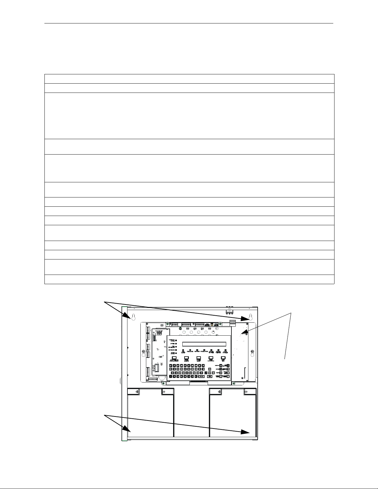
Installation Checklist Installation
Location for 1 or 2
option boards
Figure 3.1 NFS-320/E/C in Cabinet
Top two
mounting holes
Two lower
mounting holes
are behind
batteries.
3.2 Installation Checklist
Table 3.1 provides an installation checklist for installing, wiring, and testing the NFS-320/E/C
system. It has references to installation information included in manuals listed in Section 1.3
“Related Documents”.
Seq Task Refer to
1.
2.
3.
4.
5.
6.
7.
8.
9.
10.
11.
12.
13.
Mount the cabinet backbox to the wall. Section 3.3 “Mounting a Cabinet”
If adding option boards such as such as wire and/or fiber
version of the NCM/HS-NCM or TM-4:
• Remove keypad.
• Install option boards
• Replace keypad
Optional: Install auxiliary power supply and/or external
battery charger; set backup-alarm switches.
Connect AC wiring, place batteries into backbox without
connecting them, and run cable to optional power supplies,
DC power outputs, NACs, and relays.
CAUTION: Do not apply AC or DC power at this time.
Optional: Install output devices such as a printer, or CRT
terminal.
Wire annunciators and network connections. Relevant product manuals
Wire the Signaling Line Circuits. Section 3.12 “Wiring a Signaling Line Circuit (SLC)”
Terminate wire shielding as instructed. SLC Wiring Manual
Apply AC power to the control panel by placing the external circuit breaker to the ON position.
Do NOT connect batteries.
Check AC power. Table 3.2 in Section 3.5 “Connecting the Power Cables”
Connect the batteries using interconnect cable, P/N 75560 and 75561.
Program the control panel. NFS-320/E/C Programming Manual and VeriFire Tools
Field test the system. Section 5 “Testing the System”
Section 3.4 “Installing Option Boards”,
Section 1. “Remove and re-install KDM-R2 as shown in
Figure 3.2. It may be convenient to do some basic fieldwiring before reinstalling KDM-R2.”, and Section 3.4
“Installing Option Boards”
Also see option board documentation for board-specific
details.
Auxiliary power manuals, Section 3.8 “Backup-Alarm
Switches”
Section 3.5 “Connecting the Power Cables”
Section 3.11 “Installing Remote Printers and/or CRT”
Online Help.
Table 3.1 Installation Checklist
NFS-320/E/C Installation Manual — P/N 52745:M2 7/1/14 19
Page 20

Installation Mounting a Cabinet
!
3.3 Mounting a Cabinet
This section provides instructions for mounting the NFS-320/E/C backbox to a wall. The NFS320/E/C is assembled with a removable chassis that can be removed to provide easier access to the
backbox’s mounting holes, or to allow the electronics to be worked on outside the cabinet.
Follow these guidelines when mounting the backbox:
• Locate the backbox so that the top edge is 66 inches (1.6764 m) above the surface of the
finished floor.
• Access to the cabinet shall be provided in accordance with NFPA 90, article 110.33.
• Allow sufficient clearance around cabinet for door to swing freely. (See Section 2.2.5 “System
Cabinet”.)
• Use the four holes in the back surface of the backbox to provide secure mounting. (See
Figure 3.1 on page 19.)
• Mount the backbox on a surface that is in a clean, dry, vibration-free area.
CAUTION:
Unless you are familiar with the placement of components within this backbox, only use the knockout
locations provided for conduit entry.
Follow the instructions below:
1. Mark and pre-drill holes for the top two keyhole mounting bolts (0.25 inch, 0.635 cm). Use
mounting hardware appropriate for the mounting surfaces; see UL 2017 Pull-Test
Requirements.
2. Select and punch open the appropriate knock-outs. (For selection guidelines, see Section 3.9
“UL Power-limited Wiring Requirements”.)
3. Using the keyholes, mount the backbox over the two screws.
4. Mark the location for the two lower holes, remove the backbox and drill the mounting holes.
5. Mount the backbox over the top two screws, then install the remaining fasteners. Tighten all
fasteners securely.
6. Feed wires through appropriate knockouts.
3.4 Installing Option Boards
The NFS-320/E/C ships fully assembled with in its cabinet. One or two option boards can be
mounted inside the NFS-320 cabinet, under the keypad, as shown in Figure 3.3. Option boards that
can be installed internally include the wire and/or fiber versions of the NCM or HS-NCM, TM-4,
and UDACT or UDACT-2. See Section 2.3, “Compatible Equipment” for a complete list. When
installing option boards, temporarily remove the KDM-R2 keypad/display unit to provide full
access to hardware connections. It may be convenient to do some basic field-wiring before
reinstalling KDM-R2.
NOTE: UDACT or UDACT-2 only:
If using UDACT or UDACT-2 inside the cabinet, do not install a second option board.
See the UDACT Manual or UDACT-2 Manual for instructions on using the mounting bracket.
20 NFS-320/E/C Installation Manual — P/N 52745:M2 7/1/14
Page 21
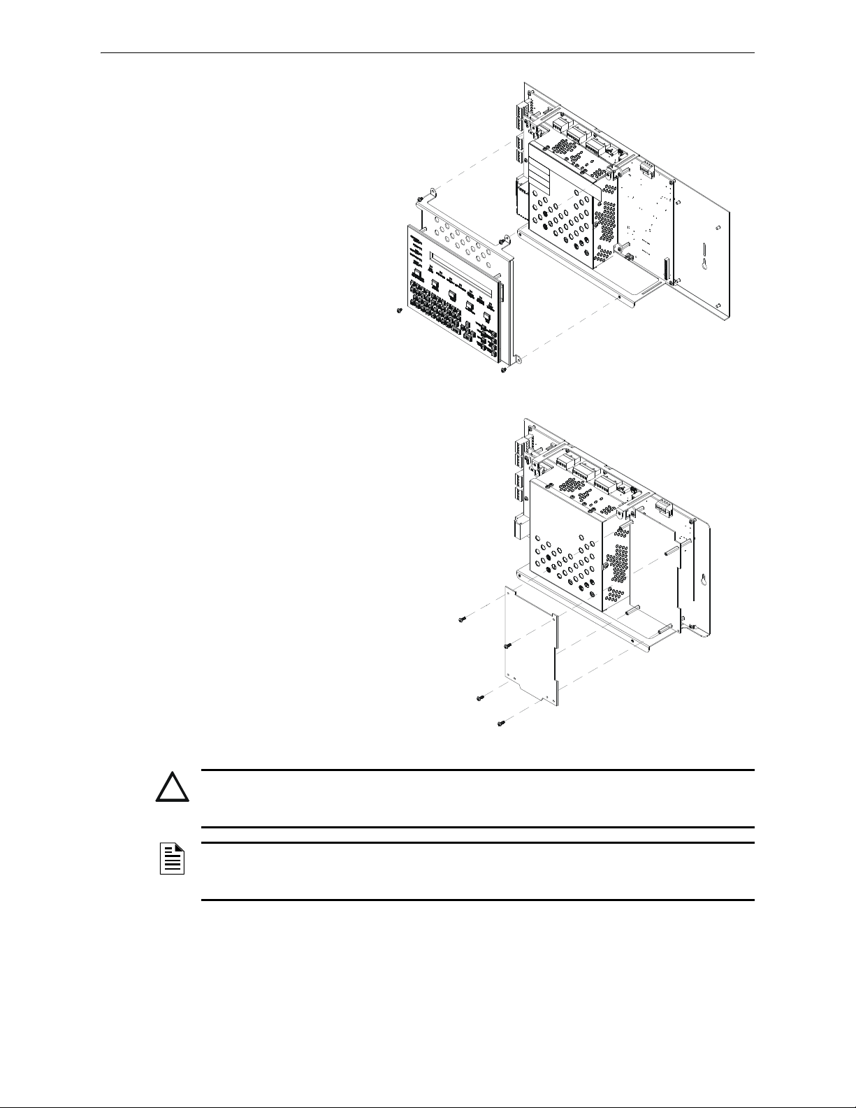
Installing Option Boards Installation
Figure 3.2 Removing and Reinstalling KDM-R2
320_assembly_tech_pubs_5 -2.wmf
Figure 3.3 Installing Option Boards
320_assembly_tech_pubs_3-2.wmf
!
1. Remove and re-install
KDM-R2 as shown in
Figure 3.2. It may be
convenient to do some
basic field-wiring before
reinstalling KDM-R2.
2. Lay the first option board
over the four stand-offs
already installed on the
CPU, so that the holes and
stand-offs align.
3. If attaching a second
option board, use its standoffs to
secure the first option board, then lay
the second option board over the
standoffs. Two sizes of standoffs are
shipped with the option boards; select
standoffs that allow sufficient
clearance for electronics on the lower
option board.
4. Secure the top option board with four
#4-40 screws (supplied).
5. Re-attach KDM-R2.
CAUTION:
It is critical that all mounting holes of the NFS-320/E/C are secured with a screw or standoff to insure
continuity of Earth Ground.
NOTE: It may be convenient to field-wire the SLC loop before installing any option boards, and
to make wiring connections on the first option board before installing a second option board in
front of it.
Installing a Transmitter Module TM-4
TM-4 is power-limited. Connections are on TB10 nonresettable output and TB11 EIA-485 ACS
Mode. Refer to the Transmitter Module TM-4 installation document for installation details.
NFS-320/E/C Installation Manual — P/N 52745:M2 7/1/14 21
Page 22
Installation Connecting the Power Cables
!
!
Network Communications Module
If networking two or more control panels or network control annunciators, each unit requires a
Network Communications Module (NCM) or a High-Speed Network Communications Module
(HS-NCM); wire and fiber versions are available for each. The wire and/or fiber versions of the
NCM or HS-NCM can be installed in any standard option-board position (see Section 3.4,
“Installing Option Boards”; the default position is immediately to the right of the control panel.
1. Mount the NCM/HS-NCM in the selected position and screw firmly in place.
2. Connect J1 on the control panel to J3 on the NCM or J6 of the HS-NCM using the network
cable provided (P/N 75556) as described in the NCM Installation Document and the HS-NCM
Installation Document. Do not connect two NCM/HS-NCMs via NUP ports (“NUP to NUP”).
3. When installing the NCM: Connect Channel A and/or Channel B as described in the NCM
Installation Document.
When installing the HS-NCM: Connect Channel A to Channel B as described in the HS-
NCM Installation Document.
NOTE: See the Noti•Fire•Net Manual or the High-Speed XLS-NET Manual and NCM Installation
Document or the HS-NCM Installation Document for wiring diagrams and system configuration
information. See the BMP-1 Product Installation Drawing if considering mounting the module
behind blank module plate in a dress plate or annunciator backbox.
NOTE: Over-bending fiber-optic cable can damage it. Do not exceed a 3 inch (7.62 cm)
minimum bend radius.
NOTE: NCM hardware is not compatible with HS-NCM hardware and should not be mixed on
the same network.
3.5 Connecting the Power Cables
WARNING:
Remove all power sources to equipment while connecting electrical components. Leave the
external, main power breaker OFF until installation of the entire system is complete.
WARNING:
Several sources of power can be connected to the control panel. Before servicing the control panel,
disconnect all sources of input power including the battery. While energized, the control panel and
associated equipment can be damaged by removing and/or inserting cards, modules, or
interconnecting cables.
3.5.1 Overview
Complete all mounting procedures and check all wiring before applying power. Electrical
connections include the following:
• Primary AC power source – 120 VAC, 50/60 Hz, 5.0 A from line voltage source (with NFS320E use 220-240 VAC, 50/60 Hz, 2.5 A). Overcurrent protection for this circuit must comply
with Article 760 of the National Electrical Code (NEC) and/or local codes. Use 12 AWG (3.31
2
mm
) wire (maximum) with a 600-volt rating.
• Secondary power source – 24 VDC from batteries, installed in the control panel (or in an
optional battery cabinet). Secondary (battery) power is required to support the system during
loss of primary power.
22 NFS-320/E/C Installation Manual — P/N 52745:M2 7/1/14
Page 23
Connecting the Power Cables Installation
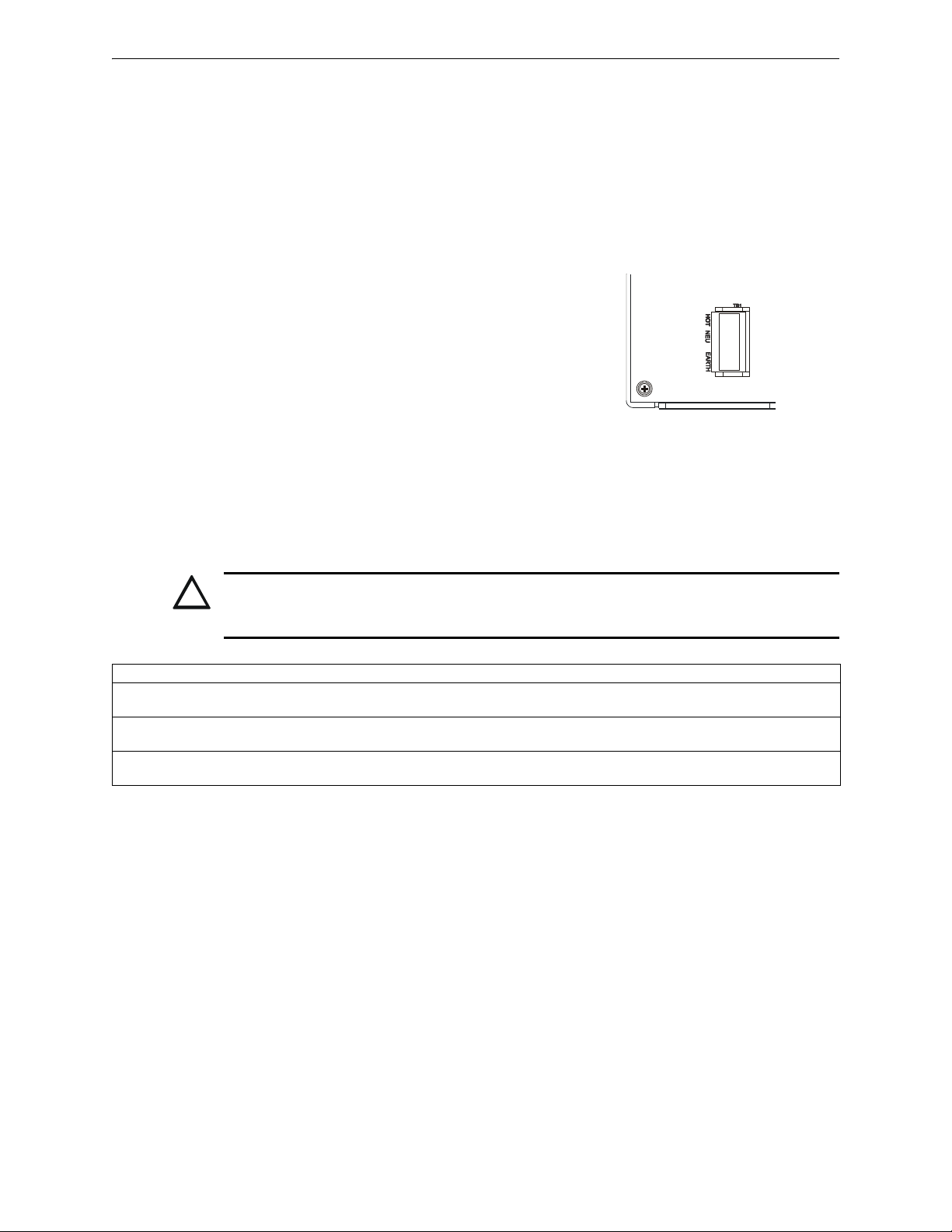
TB1 - AC Power Connection
Hot
Neutral
Ground
(Earth)
Figure 3.4 CPS-24/E:
AC Power Connections
CPS-24_TB1.wmf
!
• External power sources – 24 VDC power for Smoke Detectors (4 wire), NACs, and
Annunciators.
• Auxiliary power source – 24 VDC power @ 0.5 A and 5 VDC power @ 0.15 A from TB2 on
the CPS-24/E.
See Appendix B “Electrical Specifications” for details and overall installation guidelines.
3.5.2 Connecting the Control Panel to AC Power
Connect primary power as follows (see
Figure 3.4):
1. Turn off the circuit breaker at the main
power distribution panel.
2. Open the hinged insulating cover on TB1.
3. Connect the service ground to terminal
marked Ground (Earth).
4. Connect the primary neutral line to terminal
marked NEUTRAL and the primary Hot line
to terminal marked HOT.
5. Close the hinged insulating cover over TB1.
3.5.3 Checking AC Power
Table 3.2 contains a checklist for checking the system with AC power applied:
CAUTION:
While checking AC power, make sure batteries are not connected.
Follow the sequence of steps in Section 3.2 “Installation Checklist”, Table 3.1; this is Step 10.
Component Status
Control panel
circuit board
Each option board In an unconfigured system, the yellow Trouble indicator may come on for approximately 10 seconds after
Each auxiliary power
supply
The green AC Power indicator on; the system Trouble indicator on because batteries are not connected.
applying AC power.
The yellow Trouble indicator comes on because batteries are not connected.
Table 3.2 AC Power Checklist
NFS-320/E/C Installation Manual — P/N 52745:M2 7/1/14 23
Page 24
Installation Connecting the Power Cables
!
!
COM
COM +5V AUX
+24V AUX
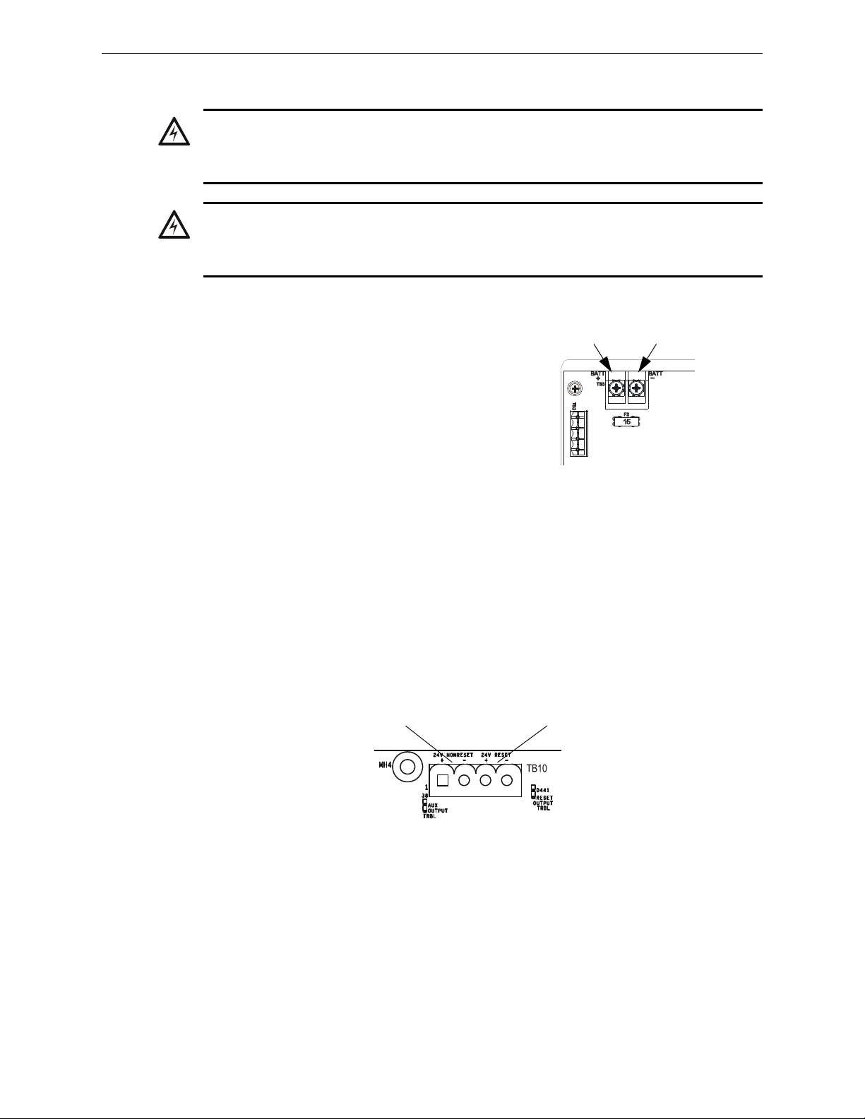
TB3 - Battery Connection
Battery (-)Battery (+)
Figure 3.5 CPS-24/E:
DC Power Connections
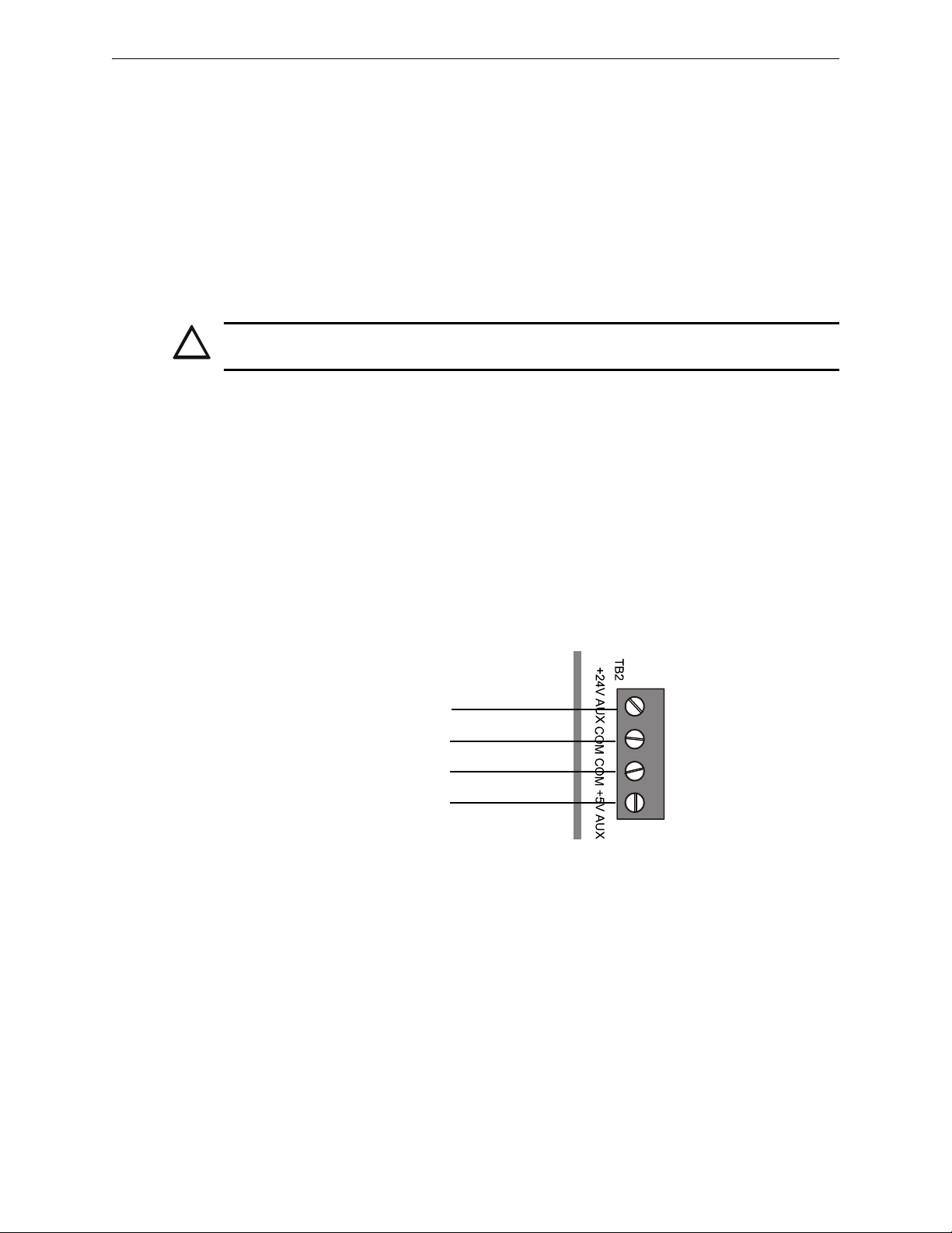
Non-resettable
Power
CPU-320-DCOut.wmf
Resettable
Power
Figure 3.6 Power Supply DC Outputs - TB10
3.5.4 Installing and Connecting the Batteries
w
WARNING:
Battery contains sulfuric acid which can cause severe burns to the skin and eyes, and can destroy
fabrics. If contact is made with sulfuric acid, immediately flush skin or eyes with water for 15 minutes
and seek immediate medical attention.
WARNING:
Do not connect the Battery Interconnect Cables (P/N 75560 and 75561) at this time. Make this
connection AFTER initial system primary powerup. Follow sequence of steps in Section 3.2
“Installation Checklist”, Table 3.1; this is Step 11.
Batteries are installed in the control panel cabinet
or in a separate battery cabinet which can be
mounted below the control panel or up to 20 feet
(6.096 m) away from the control panel, in conduit
in the same room.
Connect the battery as follows (see Figure 3.4
above):
1. Install batteries into bottom of cabinet or into
separate battery cabinet.
2. Connect the red cable from TB3(+) on the
CPS-24/E power supply to the positive (+)
terminal of one battery.
3. Connect the black cable from TB3(–) on the
CPS-24/E power supply to the negative (–) terminal of the other battery.
4. Connect the remaining cable between the negative (-) terminal on the first battery to the
positive (+) terminal on the second battery.
3.5.5 External DC Power Output Connections
Terminal TB10 provides two (2) power outputs, resettable and non-resettable. Each output is
power-limited. Follow sequence of steps in Section 3.2 “Installation Checklist”, Table 3.1; this is
part of Step 4.
24 VDC Resettable Power Circuit (Four-Wire Smoke Detectors). The power supply
provides a single 24 VDC filtered, power-limited, resettable power circuit for devices that require
resettable power (such as four-wire smoke detectors). This circuit is power-limited, but must be
supervised. To provide supervision, install a UL-listed end-of-line power supervision relay (such as
the EOLR-1) after the last device. Connect the power supervision relay normally open contact in
series with an Initiating Device Circuit (IDC). The four-wire power circuit energizes the power
supervision relay. When you reset the system, the control panel removes power from these
terminals for approximately 15 seconds.
24 NFS-320/E/C Installation Manual — P/N 52745:M2 7/1/14
Page 25
Connecting the Power Cables Installation
!
24V - Blue Wire
COM - Black Wire
5V - Red Wire
COM - Black Wire
AMPS24_TB2access.wmf
Connect external field wires to the power supply terminals TB10 RESET(+) and (–) to provide up
to 1.25 A of current for powering four-wire smoke detectors. See Figure 3.6 above. TB2 (on CPS-
24), TB10 and all 4 NACs share a maximum of 3.0 A in standby and 6.0 A in alarm.
24 VDC Non-resettable Power Circuit The power supply provides one 24 VDC filtered,
power-limited, non-resettable power output, capable of up to 1.25 A. Use this circuit to power
devices that require low-noise 24 VDC power (such as Notifier annunciator model ACM-24AT or
the transmitter module TM-4).
Connect external field wires to power supply terminals TB10 NONRESET (+) and (–) to provide
up to 1.25 A of non-resettable current for powering external devices such as annunciators. See
Figure 3.6 above. TB2 (on CPS-24), TB10 and all 4 NACs share a maximum of 3.0 A in standby
and 6.0 A in alarm.
CAUTION:
During system reset, power remains at terminals TB10 NONRESET (+) and (–).
3.5.6 Accessories DC Power Output Connections
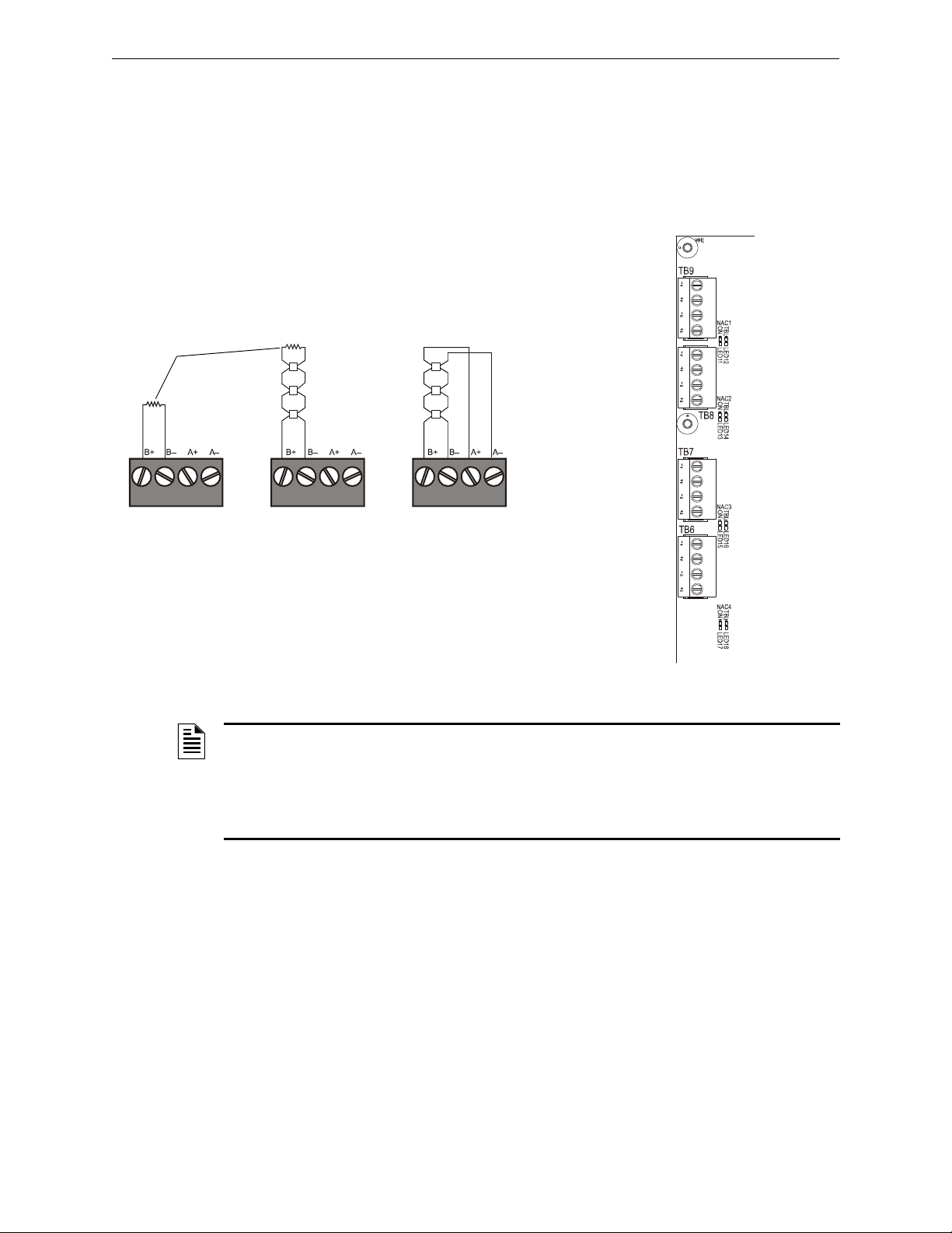
Terminal TB2 supplies one (1) non-resettable, power-limited 24 VDC circuit and one
nonresettable, power-limited 5 VDC circuit available to power external devices. Applications that
require a 5V connection to the Accessories Output, such as an UZC-256, must be within 10 feet
(3.658 meters) of the power supply. The distance from the power supply to the accessory requiring
power must not extend past the length of the supplied cable, P/N 75657 (supplied with UZC-256),
which is 10 feet long. Do not splice or otherwise extend P/N 75657. Refer to section B.2, "Wire
Requirements" of this manual for all applications requiring a 24V connection. Connect wiring with
all power sources off.
• 24 VDC (nominal) @ 0.5 A max
• 5 VDC (nominal) @ 0.15 A max
Figure 3.7 Connecting to the Accessories Output TB2 on CPS-24/E
NFS-320/E/C Installation Manual — P/N 52745:M2 7/1/14 25
Page 26
Installation NAC Connections and Releasing Circuits
nfs640-nacout.cdr
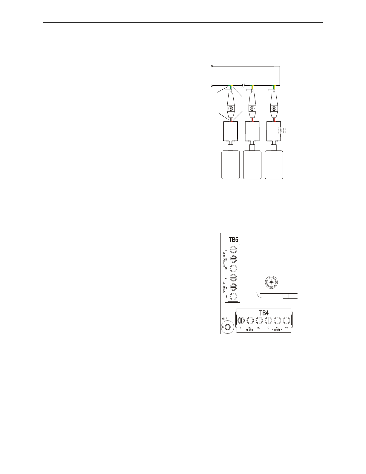
Style Y (Class B)
Connection
Style Z (Class A)
Connection
Unused Circuits
UL-listed ELR-2.2K,
1/2 W (supplied)
Figure 3.8 Notification Appliance Circuit (NAC)
Connections
Figure 3.9 NAC Terminals and NAC LEDs
TB9 - NAC#1
TB8 - NAC#2
TB7 - NAC#3
TB6 - NAC#4
CPU-320-NACS.wmf
A–
A–
A–
A–
A+
A+
A+
A+
B–
B–
B–
B–
B+
B+
B+
B+
3.6 NAC Connections and Releasing Circuits
The control panel provides four NAC terminals as shown in Figure 3.9. Each can be configured as
Style Y (Class B) or Style Z (Class A) as shown in Figure 3.8. Each circuit can provide 1.5 A of
current, but the total current drawn from the main power supply cannot exceed 7.4 A in alarm
condition (refer to Table A.2). Additionally, TB2 (on CPS-24), TB10 and all 4 NACs share a
maximum of 3.0 A in standby and 6.0 A in alarm. NAC circuits are supervised and power-limited.
Use UL-listed 24 VDC notification appliances only (refer to the Device Compatibility Document).
NOTE: Any NAC can be programmed as a releasing circuit, and the releasing circuit must
be supervised; For more information, refer to Section 4.7 “Releasing Applications” in this manual
and the NFS-320/E/C Programming Manual. Refer to the Device Compatibility Document for ULlisted compatible releasing devices. Sample connections for NAC terminals are shown in
26 NFS-320/E/C Installation Manual — P/N 52745:M2 7/1/14
Figure 3.8. Follow sequence of steps in Section 3.2 “Installation Checklist”, Table 3.1; this is part
of Step 4.
Page 27
Output Relay Connections Installation
Stat-X
Stat-X
Stat-X
REL-2.2K
Releasing Circuit
+
_
Ematch Protection
Device
P/N 3005014
Figure 3.10 Wiring Diagram for Stat-X Devices
Yellow
Green
Red
Black
StatXMultiEOL.wmf
CPU-320-relays.wmf
Figure 3.11 Form-C Relay
Connections
3.6.1 Stat-X Devices
Figure 3.10 shows typical wiring for STAT-X devices using the Ematch Protection Device (P/N
3005014). Note the following:
• Each Stat-X device requires an
Ematch Protection Device to
protect against high-voltage
transient signals, such as lightning,
that may cause the device to
accidentally release.
• Multiple Stat-X devices can be
connected in series (as shown).
• No more than ten (10) Stat-X
devices can be connected on a
single releasing circuit.
• A REL-2.2K can be installed on a
single Stat-X device for short
circuit detection. For multiple StatX devices installed in series, the
REL-2.2K is installed on the last
device on the releasing circuit (as
shown). A REL-2.2K is required for ULC applications.
• Stat-X devices are not to be used with the FCM-1 or FCM-1-REL.
3.7 Output Relay Connections
The panel provides a set of Form-C relays. These
are rated for 2.0 A at 30 VDC (resistive):
• Alarm - TB4
• Trouble - TB4
• Supervisory - TB5
• Security - TB5
These are power-limited only if connected to a
power-limited source.
Using VeriFire Tools, the Supervisory and
Security contacts can also be configured as Alarm
contacts. Follow instructions in the VeriFire Tools
online help.
NFS-320/E/C Installation Manual — P/N 52745:M2 7/1/14 27
Page 28

Installation Backup-Alarm Switches
!
Figure 3.12 Backup Alarm
Switches
CPU-320-bckalm.wmf
3.8 Backup-Alarm Switches
WARNING:
Do not enable the BACKUP option switch for any of the four Notification Appliance Circuits (NACs) if
they are used for releasing functions!
Backup alarm switches are provided that enable NACs
and the alarm relay to activate during a backup alarm
condition. If the main board’s microcontroller fails and
an alarm is reported by any detector or a monitor
module that has backup reporting enabled, the NAC
will turn on if the corresponding switch was enabled.
The alarm will activate during microcontroller failure
regardless of the settings of switches SW1-SW4.
• SW1 - NAC#1
• SW2 - NAC#2
• SW3 - NAC#3
• SW4 - NAC#4
So, for example, if SW1 and SW4 were enabled at the time of an alarm during microcontroller
failure, NAC#1 and NAC#4 would activate. Follow sequence of steps in Section 3.2 “Installation
Checklist”, Table 3.1.
28 NFS-320/E/C Installation Manual — P/N 52745:M2 7/1/14
Page 29
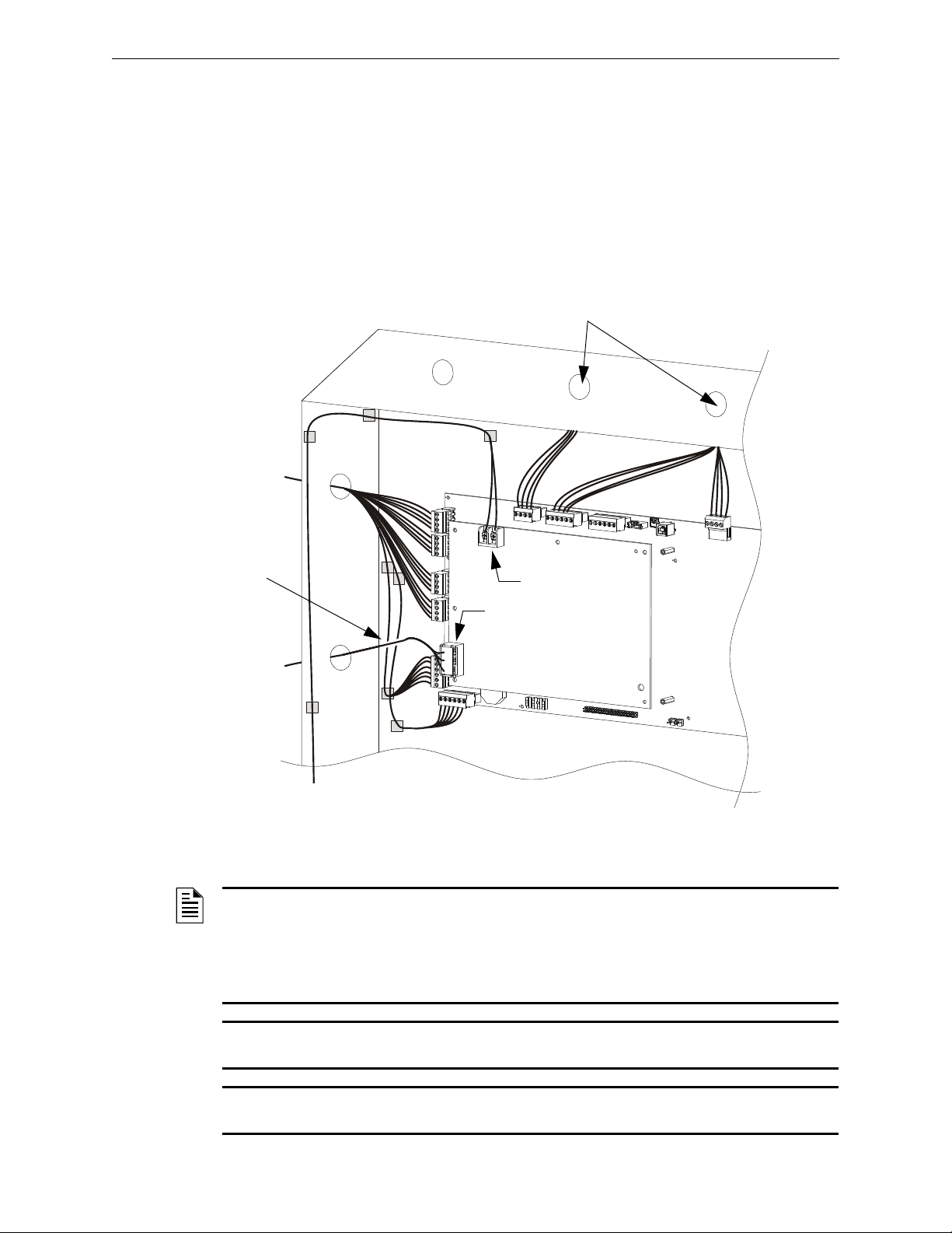
UL Power-limited Wiring Requirements Installation
640-2-PWRLMTWIR-ISO2.wmf
Figure 3.13 Typical Wiring for UL Power-limited Wiring Requirements
(Shown with relays as connected to power-limited modules)
NOTE: AC and battery wiring are not power-limited. Maintain at least 0.25 inches (6.35 mm)
between power-limited and non power-limited circuit wiring. Install tie wraps and adhesive squares
to secure the wiring. Use a power-limited source for relay output on terminals
TB5 and TB4.
See Figure 2.2, “NFS-320 and Power-Supply: Wiring Connections” on page 13 to identify powerlimited and non-powerlimited circuits.
NOTE: Drawing is not to scale; proportions and angles are exaggerated to show wire-placement
more clearly.
NOTE: If additional knockouts are added to the backbox, proper separation of power-limited and
nonpower-limited wiring should be maintained.
Power-limited Circuits*
Nonpower-
limited
circuits
To cabinet-mounted batteries
(nonpower-limited)
Power-
limited
circuits
NPL
NPL
Maintain vertical
separation where
circuits appear to
“cross”
3.9 UL Power-limited Wiring Requirements
Power-limited and nonpower-limited circuit wiring must remain separated in the cabinet. All
power-limited circuit wiring must remain at least 0.25 inches (6.35 mm) from any nonpowerlimited circuit wiring. All power-limited and nonpower-limited circuit wiring must enter and exit
the cabinet through different knockout and or conduits. To maintain separation, group non-power
limited modules together, i.e., group modules on the same side of the enclosure or in separate rows.
Figure 3.13 shows one configuration that meets these UL requirements. Equipment is configured
with at least a 0.25 inch (6.35 mm) separation between power-limited and nonpower-limited
wiring; AC and battery wiring is routed away from power-limited wiring.
NFS-320/E/C Installation Manual — P/N 52745:M2 7/1/14 29
Page 30
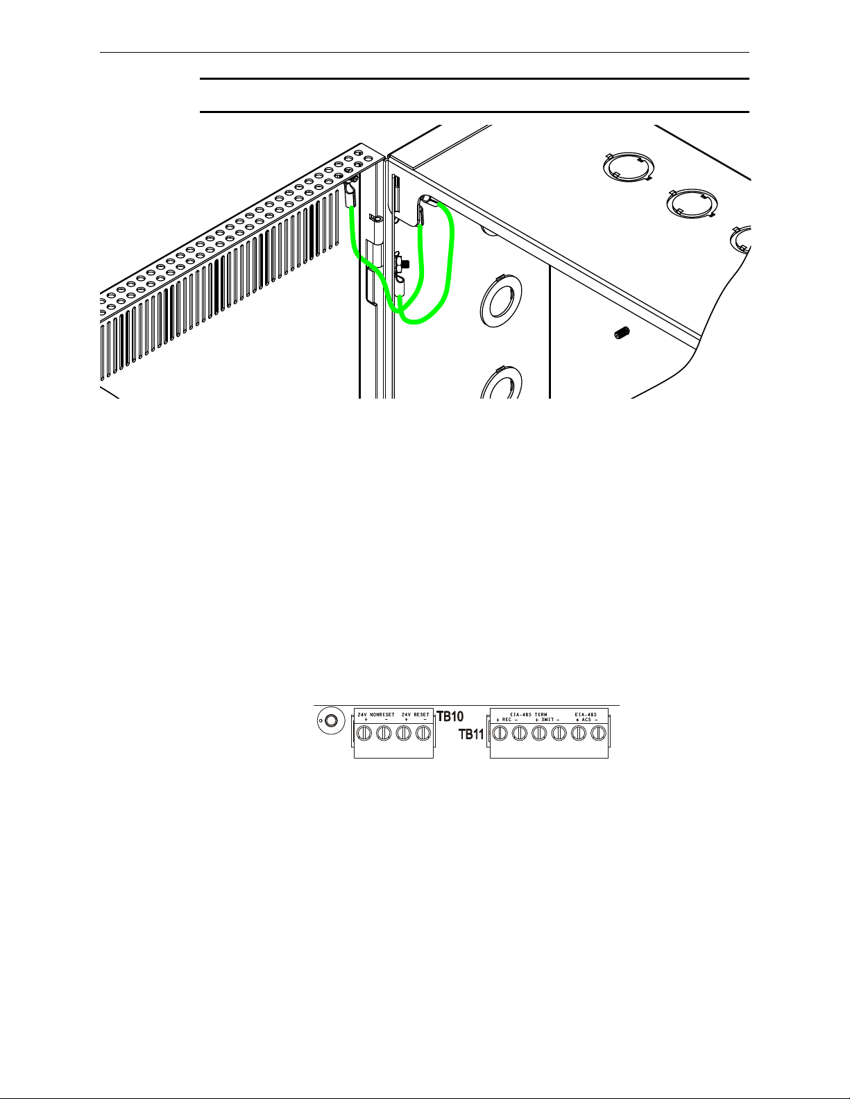
Installation Installing EIA-485 Devices
cpu2-640tb200.wmf
NOTE: In order to meet UL wiring requirements, please install grounding straps as shown below.
3.9.1 Labeling Modules and Circuits
At the time of installation, each nonpower-limited circuit connected to ACM-8R, and LDM-R32
modules must be identified in the space provided on the cabinet door label when connected to a
non-power-limited source of power.
The label lists all compatible power-limited modules and circuits; also see Figure 2.2 on page 13.
The LDM-R32 is power-limited only when connected to power-limited sources. When connected
to a non-power-limited source, the power-limited marking must be removed.
3.10 Installing EIA-485 Devices
Figure 3.14 provides a closer view of the EIA-485 connections provided on TB11. Because specific
connections can vary by the type of device being connected, refer to the product installation manual
for details.
Figure 3.14 EIA-485 Connections
3.11 Installing Remote Printers and/or CRT
3.11.1 Custom Cable Fabrication
A custom cable needs to be fabricated to connect the PRN Printer or the CRT-2 Monitor to the
system. Length of the cable will vary with each installation, but should not exceed a maximum
length of 20 feet (6.1 m). Printer must be installed in the same room as the panel, and the cable be
installed in conduit. Construct cable as follows:
1. Using overall foil/braided-shield twisted-pair cable, properly connect one end to the DB-25
Connector using the wiring specifications shown in the table below. (Custom cable kit
P/N 90106 is provided.)
30 NFS-320/E/C Installation Manual — P/N 52745:M2 7/1/14
Page 31
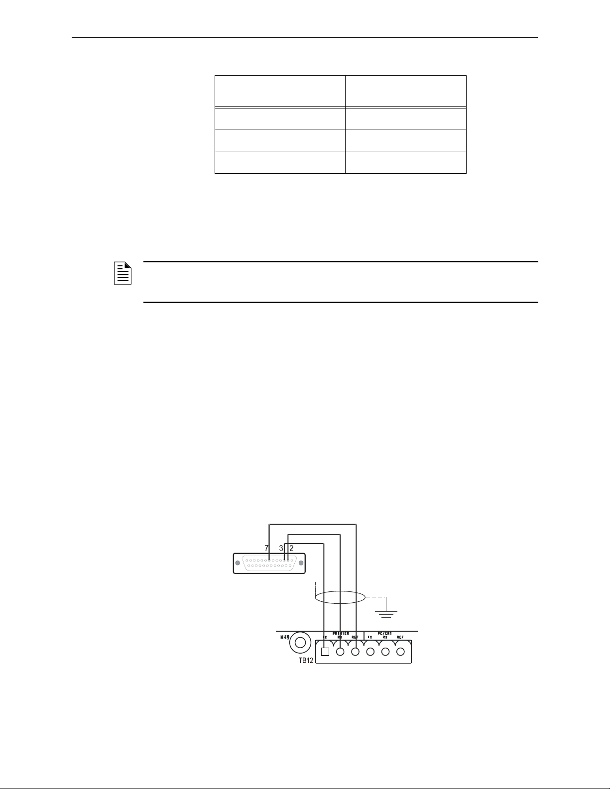
Installing Remote Printers and/or CRT Installation
Note: Outputs are power-limited
but are not supervised.
CPU-320-prn.wmf
DB-25 connector on PRN
series printer (female
socket shown)
Control Panel
Terminate one end of
shield at backbox
Figure 3.15 Remote Printer Connections
2. Tighten clamp on connector to secure cable.
DB-25 Connector
(Custom cable kit 90106)
Pin 3 TX
Pin 2 RX
Pin 7 REF
TB12 on Control Panel
3.11.2 Installing and Configuring the PRN Series Printer
When connected to the Control Panel via an EIA-232 interface, the PRN prints a copy of all status
changes within the control panel and time-stamps the printout with the time of day and date the
event occurred. It provides 80 columns of data on standard 9" by 11" tractor-feed paper.
NOTE: You can also use the EIA-232 printer interface with UL-listed information technology
equipment, such as personal computers, to monitor the control panel for supplementary
purposes.
This section contains information on connecting a printer to the control panel and for setting the
printer options.
Connecting a Remote PRN Series Printer
Remote printers require a 120 VAC, 50/60 Hz primary power source. If required for the fire alarm
system configuration (for example, a Proprietary Fire Alarm System), a remote printer requires a
secondary power source (battery backup). Because a secondary power source is not provided, use a
separate Uninterruptable Power Supply (UPS) that is UL-listed for Fire Protective Signaling. You
may use your building emergency power supply, so long as it meets the power continuity
requirements of NFPA 72. Refer to NFPA 72 for further details.
Connect the remote printer to the Control Panel as follows:
1. Connect the three (3) open leads of the custom cable to the TB12 terminal block on the control
2. Plug the DB-25 connector end of the custom cable into the EIA-232 port of the remote printer.
panel as shown in Figure 3.15.
Tighten securely.
NFS-320/E/C Installation Manual — P/N 52745:M2 7/1/14 31
Page 32
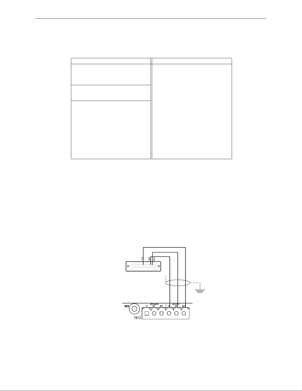
Installation Installing Remote Printers and/or CRT
DB-25 connector
on CRT-2
(female socket shown)
Control
Panel
nfs640-crt2conn.cdr
Terminate one end of
shield at backbox
Figure 3.16 Connecting a CRT-2
Setting Printer Options
Refer to the documentation supplied with the PRN series printer for instructions on using the
printer menu controls. Set the printer options (under the menu area) according to the settings listed
in Table 3.3.
Option Setting Option Setting
Font
LPI
ESC Character
Bidirectional Copy
CG-TAB
Country
Auto CR
Color Option
Formlen
Lines
Standard
HS Draft
6 LPI
ESC
ON
Graphic
E-US ASCII
OFF
Not Installed
6LPI=60
Exec 10.5
CPI
Skip
Emulate
I/O
Buffer
Serial
Baud
Format
Protocol
Character Set
Sl.Zero
Auto LF
PAPER
BIN 1
BIN 2
SINGLE
PUSH TRA
PULL TRA
PAP ROLL
10 CPI
0.5
Epson FX-850
40K
9600, 4800, or 2400
7 Bit, Even, 1 Stop
XON/XOFF
Standard
On
Off
12/72"
12/72"
12/72"
12/72"
12/72"
12/72"
Table 3.3 PRN Setup Options
3.11.3 Installing and Configuring a CRT-2
A CRT-2 can only be used in a non-networked application when used with the NFS-320/E/C. For
further details on setting up the CRT-2, refer to the NFS-320/E/C Operations Manual.
Connect a CRT-2 to the Control Panel as follows:
1. Connect the three (3) open leads of the custom cable to the TB12 terminal block on the control
panel as shown in Figure 3.16.
2. Plug the DB-25 connector end of the custom cable into the EIA-232 port of the CRT-2. Tighten
securely.
3. Set parameters as discussed in Table 3.16.
32 NFS-320/E/C Installation Manual — P/N 52745:M2 7/1/14
Setting CRT-2 Parameters
The CRT-2 communicates with the control panel through a protocol defined by thirteen groups of
parameters. To access a parameter group, press the corresponding function key (F1-F12) as shown
in Table 3.4 below. You can then program parameters in each group.
Page 33

Installing Remote Printers and/or CRT Installation
Enter the CRT-2 setup menu by pressing and holding the <Ctrl> key while pressing the <Scroll
Lock> key. Use arrow keys to move through the selections in each setup group; press the space bar
to view the options for each parameter. When finished programming all setup groups, press the
<Pause> key. To save all changes, press <Y>.
Table 3.4 shows the standard settings for using the CRT-2 with the NFS-320/E/C; for one instance
where these settings may change slightly see Section 3.11.4 “Connecting Multiple Printers, CRTs,
or CRT/PRN Combination”. The basic settings for using the CRT-2 with NFS-320/E/C are:
• Baud Rate 9600 • Data format 8 1 N • Protocol xon/off.
NOTE: This section covers installation only; for information on how the CRT-2 functions as part
of the fire alarm system, see the NFS-320/E/C Operations Manual.
NOTE: The CRT cannot be connected at the same time as the network.
Function Key CRT-2 Parameters
F1: Quick
(“Read Status” key)
F2:Genrl
(“Alter Status” key)
F3: Displ
(“Prog” key)
F4: Kybd
(“Spl Funct” key)
F5: Keys
(“Prior” key)
F6: Ports
(“Next” key)
F7: Host
(“Auto Step” key)
F8: Print
(“Activ Signal” key)
F9: Emul Attribute=Page
F10 Setup Group F10 does not affect communications with the control panel.
F11 Setup Group F11 does not affect communications with the control panel.
F12: Prog
(“Ack Step” key)
Emulation=CRT-2
Comm Mode=Full Duplex
Enhanced=On
Emulation=CRT-2
Auto Font Load=On
Monitor Mode=Off
Host/Printer=EIA/Aux
Page Length=24
Display Cursor=On
Columns=80
Scroll=Jump
Language=U.S.
Keyclick=Off
Key Lock=Caps
Enter Key=<CR>
Alt Key=Meta
Pound Key=U.S.
EIA Baud Rate=9600
Aux Baud Rate=9600
EIA Xmt=Xon-Xoff
Aux Xmt=Xon-Xoff
EIA Break=Off
Aux Break=Off
Comm Mode=Full Duplex
Recv <DEL>=Ignore
Send Block Term=<CR>
Prnt Line Term=<CR><LF> Prnt Block Term=<CR> Secondary Recv=Off
WPRT Intensity=Dim
WPRT Blink=Off
Status Line=Off
Program the function keys as follows: F1 ~A F2 ~B F3 ~C F4 ~D F5 ~E F6 ~F F7 ~G
F8 ~H F9 ~I F10 ~J F11 ~K F12 ~L F13 ~M F14 ~N F15 ~O F16 ~P Shift F13 ~Q
EIA Baud Rate=9600
Aux Baud Rate=9600
Language=U.S.
Enhanced=On
Auto Page=Off
Bell Volume=09
Screen Length=26 Lines
Cursor=Blink Line
Width Change Clear=Off
Refresh Rate=60 Hz
Char Set Mode=ASCII
Key Repeat=Off
Keyboard Present=Yes
Return Key=<CR>
Disconnect=Pause
EIA Data Format=8/1/N
Aux Data Format=8/1/N
EIA Recv=Xon-Xoff(XPC)
Aux Recv=Xon-Xoff(XPC)
EIA Modem Control=Off
Aux Modem Control=Off
Local=Off
Send ACK=On
Null Suppress=On
Bright Video=Off
WPRT Reverse=Off
Display NV Labels=Off
Fkey Speed=Normal
EIA Data Format=8/1/N
Aux Data Format=8/1/N
Host/Printer=EIA/Aux
Auto Wrap=Off
Auto Scroll=On
Warning Bell=On
Screen Video=Normal
Auto Adjust Cursor=On
Speed=Normal
Overscan Borders=Off
Key Mode=ASCII
Margin Bell=Off
Backspace=<BS>/<DEL>
Desk Acc=Disabled
EIA Parity Check=On
Aux Parity Check=On
EIA Xmt Pace=Baud
Aux Xmt Pace=Baud
EIA Disconnect=2 sec
Aux Disconnect=2 sec
Recv <CR>=<CR>
Send Line Term=<CR><LF>
Page Edit=Off
WPRT Underline=Off
Save Labels=On
Table 3.4 Standard CRT-2 Settings for Use with NFS-320/E/C
3.11.4 Connecting Multiple Printers, CRTs, or CRT/PRN Combination
Connecting multiple devices requires changing the CRT-2 setup using the F1(Quick) menu:
NFS-320/E/C Installation Manual — P/N 52745:M2 7/1/14 33
Page 34
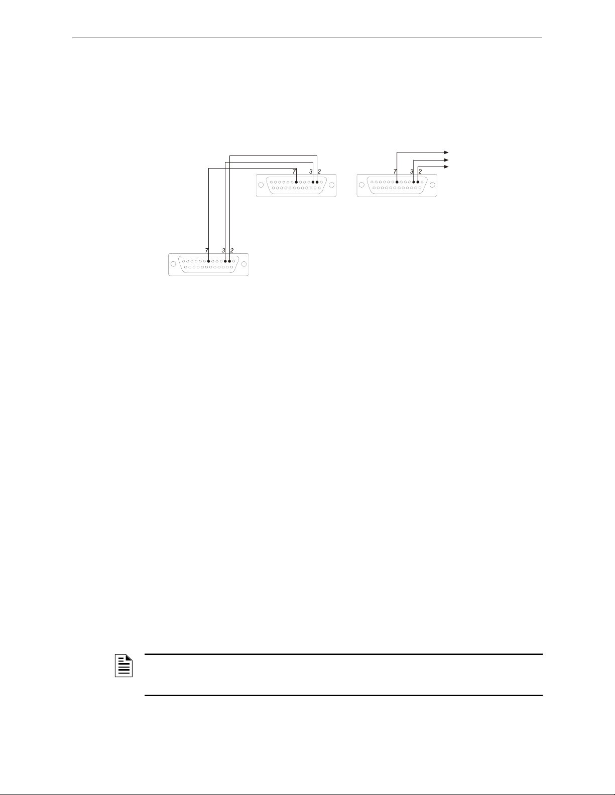
Installation Wiring a Signaling Line Circuit (SLC)
To Control Panel
TB12-PC/CRT REF
TB12-PC/CRT TX
TB12- PC/CRT RX
To EIA-232 port of CRT-2
(female socket shown)
To AUX Port of CRT-2
(female socket shown)
To EIA-232 port of next
CRT-2 or PRN (female socket shown)
prncrt-conn.cdr
Note: For wire requirements, see Table B.1 in Appendix B “Electrical Specifications”.
Figure 3.17 Connecting Multiple Devices on the EIA-232 Circuit
• Set Host/Printer=EIA/AUX.
• Set EIA Data Format=8/1/N.
• If the AUX device is a printer, set the Printer and AUX Data Format=7/1/E.
• If the AUX device is a second CRT-2, set the AUX Data Format=8/1/N.
Connect multiple devices as shown in Figure 3.17.
3.12 Wiring a Signaling Line Circuit (SLC)
Overview
Communication between the control panel and intelligent and addressable initiating, monitor, and
control devices takes place through a Signaling Line Circuit (SLC). You can wire an SLC to meet
the requirements of NFPA Style 4, Style 6, or Style 7 circuits.
This manual provides requirements and performance details specific to this control panel; for
installation information and general information, refer to the SLC Wiring Manual.
Wiring
Maximum wiring distance of an SLC using 12 AWG (3.31 mm
total twisted-pair for Style 4, Style 6 and Style 7 circuits.
Capacity
The NFS-320/E/C provides one (1) SLC, with a total capacity of 318 intelligent/addressable
devices:
• 01-159 intelligent detectors
• 01-159 monitor and control modules
Units employing multiple detector operation shall include a minimum of two detectors in each
protected space and reduce the detector installation spacing to 0.7 times the linear spacing in
accordance with National Fire Alarm Code, NFPA. For spacing requirements refer to the detector’s
installation instructions.
2
) wire is 12,500 feet (3810 meters)
NOTE: To meet the ten-second response time required by UL 864, 9th edition, when SLC loops
are configured to run in CLIP mode, all input modules must be mapped to address 19 and lower.
There are no limits to detectors or output modules.
34 NFS-320/E/C Installation Manual — P/N 52745:M2 7/1/14
Page 35
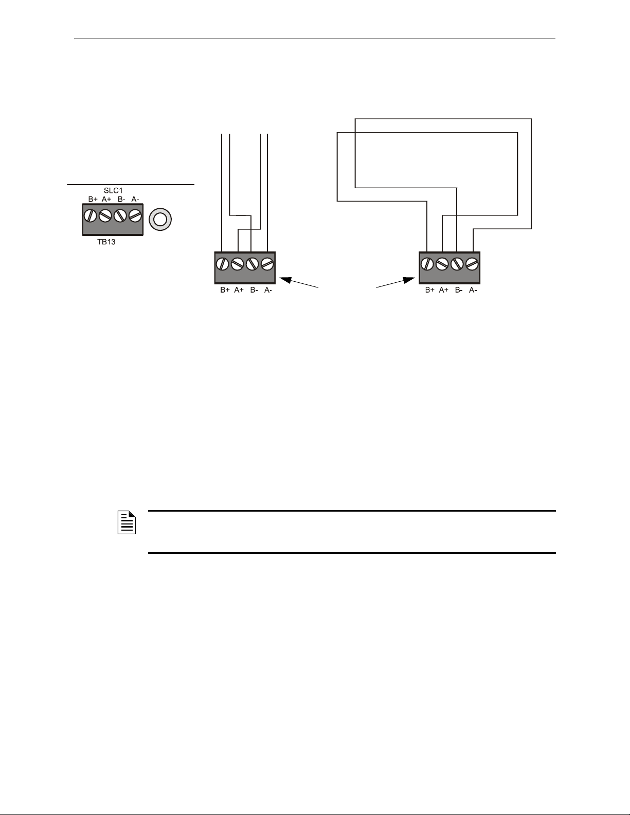
Connecting a PC for Off-Line Programming Installation
Note: T-Tapping is not allowed on a four-wire SLC.
SLC B (output loop)
SLC A (loop return)
SLC B SLC A
Style 4 SLC Loops Style 6 SLC Loops
SLC Loop Connections
on FACP’s main circuit board
TB13 on
NFS-320/E/C
nfs640-slcloops.cdr, CPU-320-SLC-TB.wmf
Figure 3.18 SLC Loop Connections and Wiring
Installation
This control panel supports one SLC loop, which connects to TB13 on the control panel. For details
on designing, installing and configuring SLC loops, see the SLC Wiring Manual.
3.13 Connecting a PC for Off-Line Programming
A PC can be hooked up to the control panel to allow the VeriFire Tools programming utility to
upload and download the operating program. Refer to the insert in the VeriFire Tools CD and to the
program’s on-line help function for instructions. There are two options for connection:
Two options are available.
1. For PCs with USB Ports, connect the PC to USB B via a standard USB B cable.
2. For PCs without USB Ports, connect the PC’s serial port to the Control Panel’s
Network/Service Connection (J1, NUP).
NOTE: Download operations that change the basic program of the control panel must be
performed by responsible service personnel in attendance at the control panel. After downloading
a program, test the control panel in accordance with NFPA 72.
NFS-320/E/C Installation Manual — P/N 52745:M2 7/1/14 35
Page 36

4.1 Overview
• Control
•Strobe
• Horn
• (Blank)
• Release Ckt
• Rel Ckt Ulc
• Nonreset Ctl
• Alarms Pend
•Gen Alarm
•Gen Supervis
• Gen Trouble
• Gen Pend
• Trouble Pend
Chapter Covers the following topics
Section 4: Applications
Section 4.3 “NFPA 72 Central or
Remote Station Fire Alarm System
(Protected Premises Unit)”
Section 4.5 “NFPA 72 Proprietary
Fire Alarm Systems”
Section 4.6 “Fire/Security
Applications”
Section 4.7 “Releasing
Applications”
How to install UDACT/UDACT-2 with the control panel for use as a
NFPA Central or Remote Station Fire Alarm System (Protected
Premises Unit)
How to set up a Protected Premises Unit to communicate with a listed
compatible Protected Premises Receiving Unit.
How to use the control panel as a combination Fire/Security system,
including the following:
• Installing a Security Tamper Switch into the cabinet
• Circuit Wiring
How to install the following releasing applications:
• Releasing Device to the Control Panel (NAC integral circuits)
• Releasing Device to the FCM-1 Module
• NBG-12LRA Agent Release-Abort Station
Municipal Box (Auxiliary)
Municipal Box applications require a TM-4 Transmitter module. Refer to the TM-4 Transmitter
Module installation document for installation details.
4.2 Devices Requiring External Power Supervision
With version 12.0 and higher, certain type codes have external power supervision (FlashScan only)
built into the software. An external power-supervision relay is required (see Figure 4.1) unless one
of the following typecodes is selected for the device:
36 NFS-320/E/C Installation Manual — P/N 52745:M2 7/1/14
Page 37
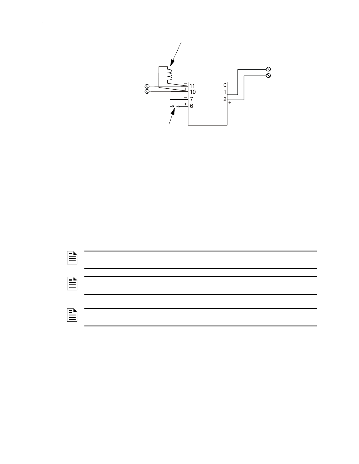
NFPA 72 Central or Remote Station Fire Alarm System (Protected Premises Unit) Applications
Device to be
Supervised
Non-resettable 24
VDC Power from
a listed source
–
+
–
+
SLC from FACP
FCM-1
N.C. Supervision
Relay Contact
Part of EOLR-1
(Not required for
FlashScan type codes
that provide built-in
power supervision.)
Power Supervision
Relay (EOLR-1)
(Not required for
FlashScan type codes
that provide built-in
power supervision.)
3030-external-power-suptpH.wmf
*If the SLC device does
not match the one in this
figure, refer to the SLC
manual appendix, which
contains wiring conversion
charts for type V and type
H modules.
Figure 4.1 Enabling External Power Supervision Using Relays
4.3 NFPA 72 Central or Remote Station Fire Alarm System (Protected Premises Unit)
Figure 4.2 shows typical wiring diagram for a NFPA 72 Central Station Fire Alarm System
(Protected Premises Unit) or a Remote Station Fire Alarm System (Protected Premises Unit) using
the Universal Digital Alarm Communicator/Transmitter (UDACT or UDACT-2) and control panel.
This provides typical wiring only; connect and program the UDACT or UDACT-2 according to the
directions given in the UDACT Instruction Manual or UDACT-2 Instruction Manual.
NOTE: An NFPA 72 Central Station or Remote Station requires 24 hours of standby power and 5
minutes in alarm.
NOTE: This application can also be done with the TM-4 Transmitter; refer to the TM-4
Transmitter Module installation document for more details.
NOTE: For additional setup information for the UDACT-2, refer to the UDACT-2 Instruction
Manual.
NFS-320/E/C Installation Manual — P/N 52745:M2 7/1/14 37
Page 38
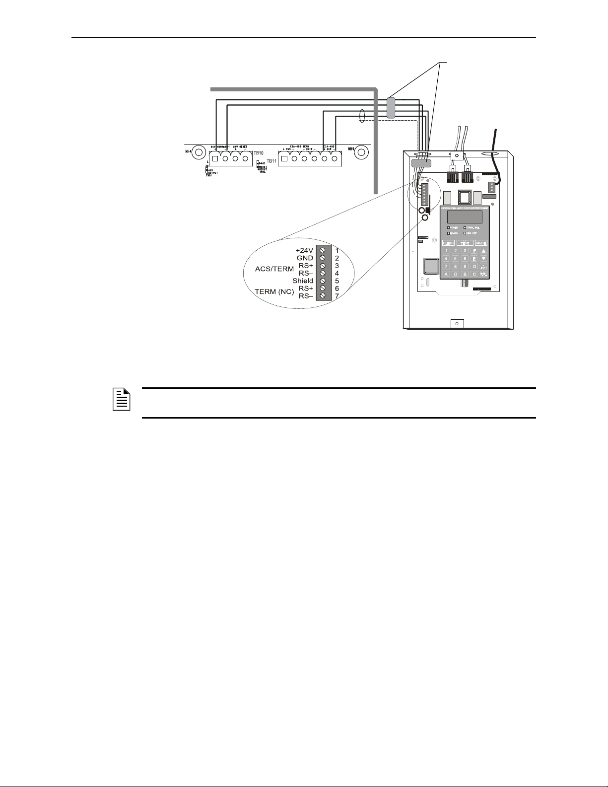
Applications NFPA 72 Central or Remote Station Fire Alarm System (Protected Premises Unit)
UDACT in ABS-8RB
(shown with cover removed)
Solid earth
ground
To supervised
phone lines
Ferrite cores
P/N 29090
FACP Cabinet
EIA-485
(ACS Mode)
24 VDC
Nonresettable power
Supervised and power-limited
EIA-485 and power wiring
CPU-320-udact.wmf
Figure 4.2 Typical Wiring Diagram for a Central Station Fire Alarm System
NOTE: Install a UL-listed 120 ohm End-of-Line resistor (P/N 71244) UDACT TB1 terminals 3
and 4 if this is the last or only device on EIA-485 line.
38 NFS-320/E/C Installation Manual — P/N 52745:M2 7/1/14
Page 39
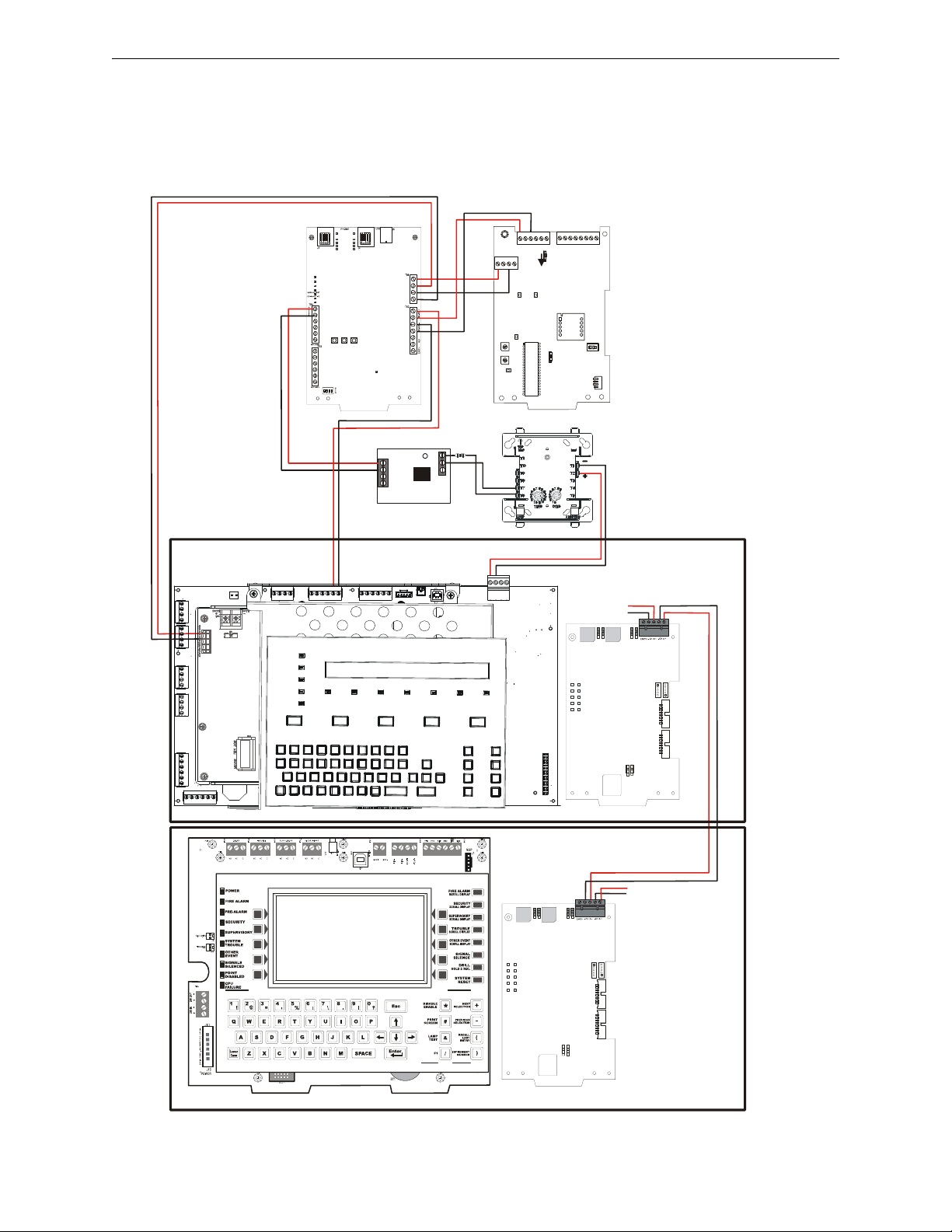
0
NO
ON
NC
C
18/24
115
230
1
1
S5W
LED3
LED4
LED1LED2
S1W
ELR
TXACS
RXACS
POWER
TROUBLE
SW4
REMOTE
STATION
ALARM
ACS
TB2 TB1
ACS REF
REMOTE
STATION
SUPERVISORY
MUNICIPAL
BOX
REMOTE
STATION
TROUBLE
T3B
S2W
S3W
SW6
NON-ISOLATED
DISABLE
ISOLATED
ENABLE
+24VDC
REF
+
-
LINE SEIZE
LED 3
LED 20
LED 8
LED 2
LED 1
LED 9
LED 14
LED 13
+ 24V
COMMON
INPUT 1
INPUT 2
INPUT 3INPUT 4INPUT 5
TRANS
CLEAR
SW1
SW2
SW3
SW4
RESET
TEST
REPORT
REAL TIME
EIA-485 COMM LOSS
POWER
LED 5
LED 6
LED 7
LED 17
LED 18
LED 19
LED 4
LED 15
LED 16
LINE FAIL
NO TONE
KISS OFF
COMM FAIL
PRI
SEC
OPTION
SELECT
SWITCH
1 2 3 4
OFF
ON
ON
LED21
TONE DETECT
RECON
PULSE1
LED6 LED7
LED101
LED100
LED4 LED2
LED3 LED5
LED1 LED8
STATA
STATB
RCDA RCDB
A HI
B HI
EF B TERM B
SW101
SW102
SW103
ON OFF
EF A TERM A
SW100
ON OFF
NUP1
NUP2
J3 J2
LCMATERM
A
SW1
ON
SW2
OFF
LCM ALCM B
RESET
POWER
RECON
PULSE1
LED6 LED7
LED101
LED100
LED4 LED2
LED3 LED5
LED1 LED8
STATASTATB
RCDA RCDB
A HI
B HI
EF B TERM B
SW101
SW102
SW103
ON OFF
EF A TERM A
SW100
ON OFF
NUP1
NUP2
J3 J2
LCMATERM
A
SW1
ON
SW2
OFF
LCM ALCM B
RESETPO WER
EIA-485
24V
Relay
Drive
24V
EIA-485
24V
+
_
+
+
+
+
+
NFS-320
NCM-W
To Previous
Node on
Network
To Next Node
on Network
NCA-2
NCM-W
_
_
_
_
_
TM-4
UDACT-2
MR-101/C
FMM-1
SLC
+
NOTES:
• Drawing is not to scale.
• The UDACT/UDACT-2 should
be set for “Receive Only” for
this configuration. For
additional UDACT/UDACT-2
setup information, refer to the
UDACT Installation Manual. or
UDACT-2 Instruction Manual.
• This illustration is show with
the NCM-W. For other NCM or
HS-NCM setup, refer to the
NCM Installation or HS-NCM
Installation documents.
• For additional setup information
on the TM-4, refer to the TM-4
Instruction Manual.
EIA-485
{
{
{
{
24V
EIA-485
_
Central Station Fire Alarm System Canadian Requirements Applications
4.4 Central Station Fire Alarm System Canadian Requirements
For Canadian applications requiring a second dial-out option, refer to the following illustration for
UDACT/UDACT-2 and TM-4 setup:
Figure 4.3 Central Station Canadian Requirements for Second Dial-Out Connection
NFS-320/E/C Installation Manual — P/N 52745:M2 7/1/14 39
Page 40
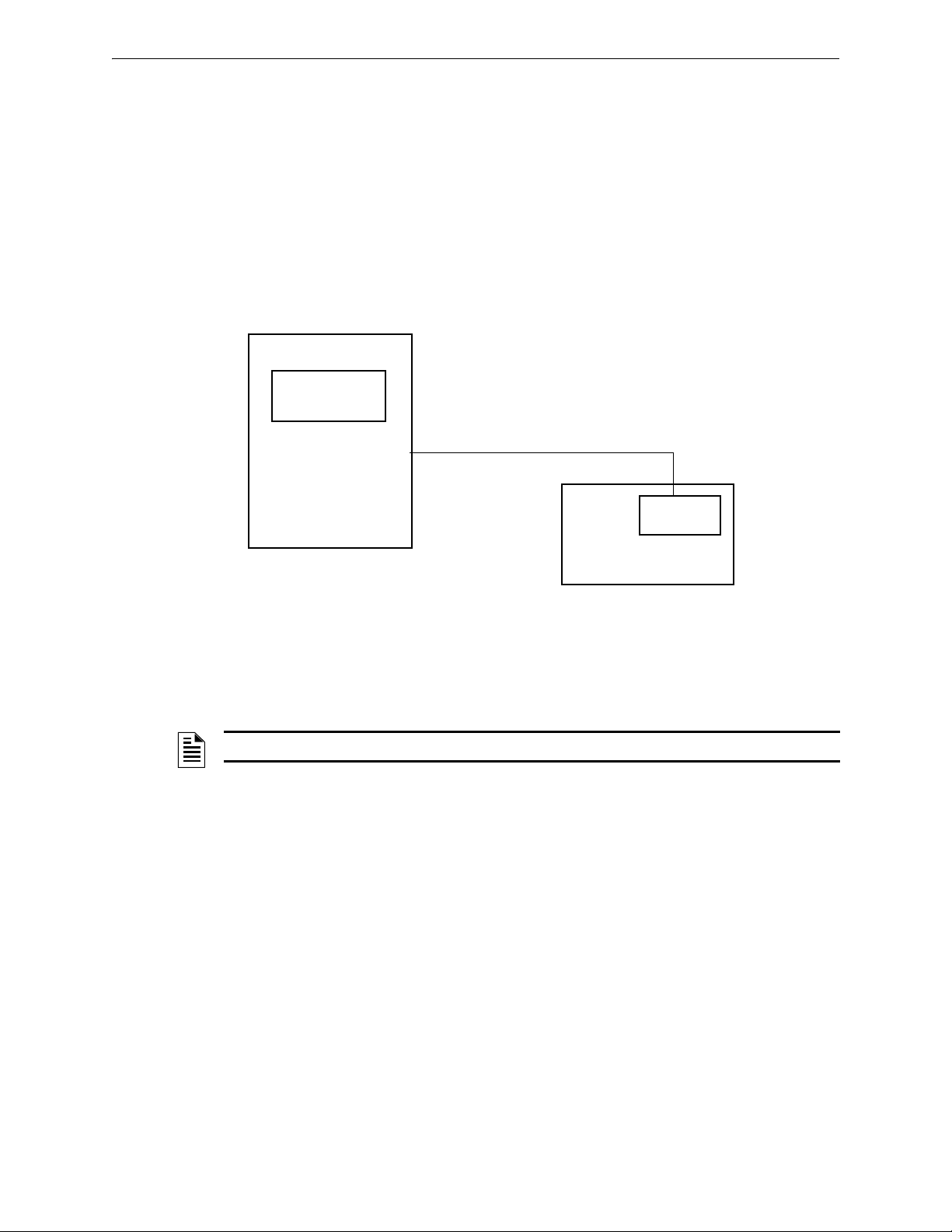
Applications NFPA 72 Proprietary Fire Alarm Systems
NFS-320/E
Protected Premises Unit
Compatible Receiving Unit
(see UDACT Manual or UDACT-2
Manual)
Telephone line and backup
UDACT
or UDACT-2
NFS-320/E
Figure 4.4 Typical Proprietary Fire Alarm Systems Wiring Connections
4.5 NFPA 72 Proprietary Fire Alarm Systems
When connected and configured as a protected premises unit with UDACT or UDACT-2, the NFS320/E will automatically transmit General Alarm, General Trouble, and General Supervisory
signals to a listed compatible Protected Premises Receiving Unit. See the UDACT Manual or
UDACT-2 Manual for compatible receiving units. A simplified drawing of connections between the
receiving unit and the NFS-320/E protected premises unit is shown in Figure 4.4.
Connect the receiving unit to the protected premises unit as shown in Section 4.3 “NFPA 72 Central
or Remote Station Fire Alarm System (Protected Premises Unit)”.
For information on installing and programming the Receiving unit, refer to the documentation for
that control panel.
4.6 Fire/Security Applications
NOTE: NFS-320/E/C is not approved for use in security applications in Canada.
4.6.1 General Operation
The control panel can be used as a combination Fire/Security system when installed and operated
according to the instructions in this section.
For security applications, program one or more monitor modules (listed for security applications)
with the
lights the
The panel sounder will sound until the Security alarm is acknowledged. You can also program
additional sounders or output devices to activate with the security alarm initiating device. The
SECURITY Type Code is designed to indicate an alarm as follows: (a) on an open or short circuit; or
(b) on a ±50% change in resistance value from the End-of-Line resistor value.
A tamper switch installed in the cabinet door will indicate a door tamper condition whenever the
door is open. If the control panel indicates a Security alarm, you can acknowledge, silence, and
reset the condition from the control panel.
When the system resets, a 30-second exit timer starts. During this time the tamper switch and all
Security alarms are ignored. There is no entrance delay timer.
40 NFS-320/E/C Installation Manual — P/N 52745:M2 7/1/14
SECURITY Type Code, and wire as shown in Figure 4.6. Activating this type of module
SECURITY LED, and displays a security alarm condition on the control panel LCD display.
Page 41
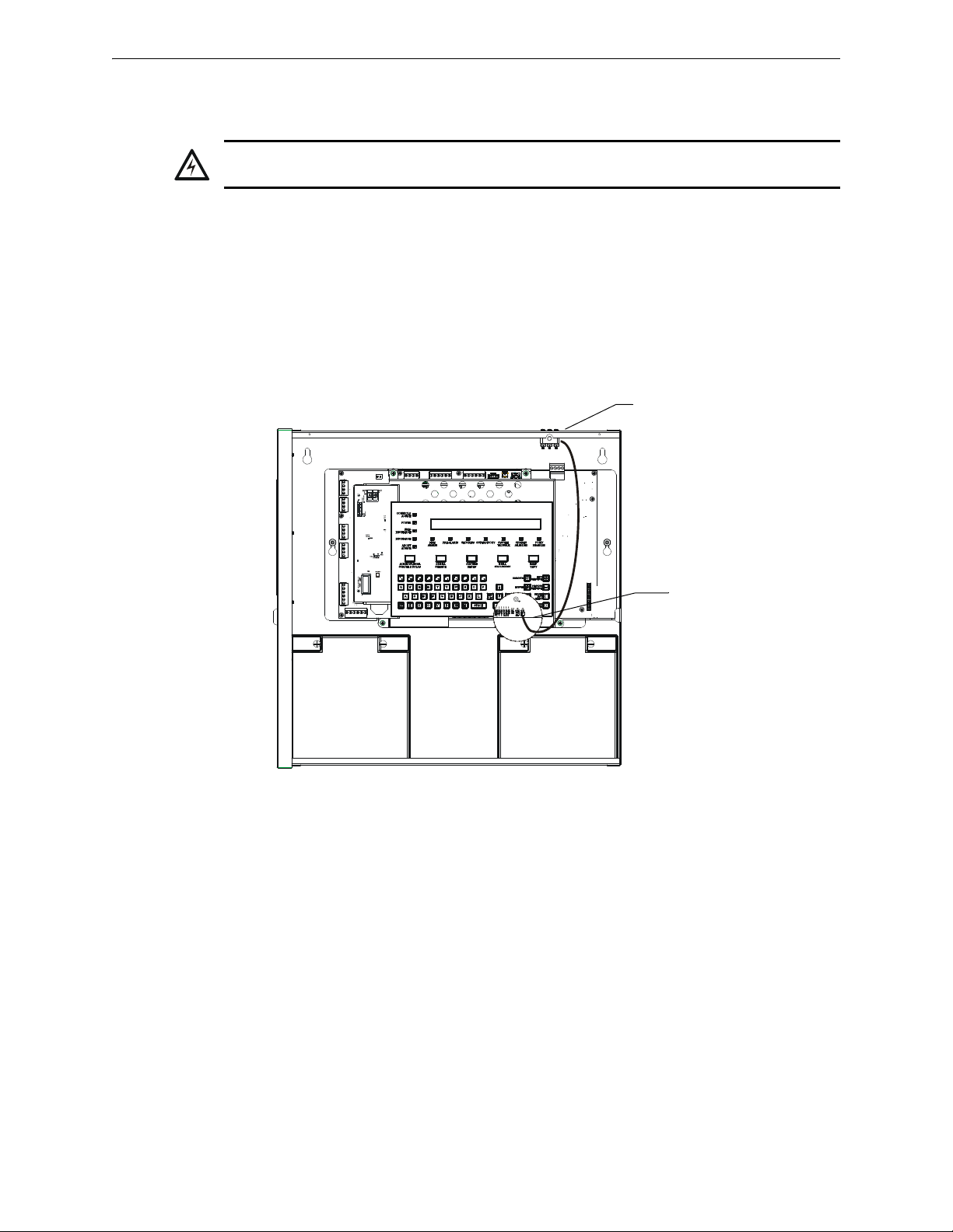
Fire/Security Applications Applications
!
320_STS1.wmf
Connect to
J5 “Security Tamper”
STS-200 mounting
location
Figure 4.5 Installing the STS-200 Security Tamper Switch
For bypass of security zones, use the DISABLE routine (covered in the Status Change section of
the NFS-320/E/C Operations Manual) for Security type devices.
WARNING:
Damage can result from incorrect wiring connections.
4.6.2 Installing a Security Tamper Switch
To wire the cabinet with a Security Tamper Switch kit model STS-200, refer to Figure 4.5:
1. Install the STS-200 Tamper Switch into the location shown in Figure 4.5. Push the switch
through the opening until it snaps into place.
2. Connect the STS-200 connector to J5 (Security Tamper) on the Control Panel. (As shown in
Figure 4.5, J5 is located on the circuit board, underneath the edge of KDM-R2.)
4.6.3 Receiving Unit
For applications requiring transmission of security alarm information to a central receiving unit, the
control panel may be connected via the UDACT or UDACT-2 to a compatible receiving unit (see
the UDACT Manual or UDACT-2 Manual). For information on configuring the Receiving unit for
Combination Fire/Security applications, refer to the documentation for that control panel.
4.6.4 Programming
The control panel can communicate with any number of security devices. To do so, program the
points as follows:
1. Select the address of the module(s) to be used for security.
NFS-320/E/C Installation Manual — P/N 52745:M2 7/1/14 41
Page 42
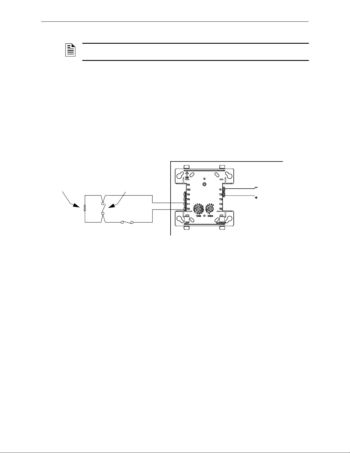
Applications Fire/Security Applications
FlashScan Monitor Module
UL-listed, normally-closed
security switch
UL-listed,
normally-open
security switch
SLC
Channel
A or B
NFS-320/E Protected Premises Unit
CPU2-640-burgtpH.wmf
UL-listed 47K
End-of-Line Resistor
(provided with module)
*If the SLC device does
not match the one in this
figure, refer to the SLC
manual appendix, which
contains wiring conversion
charts for type V and type
H modules.
2. Select the Type Code SECURITY.
NOTE: For detailed instruction on programming Type Codes, refer to the NFS-320/E/C
Programming Manual.
4.6.5 Wiring for Proprietary Security Alarm Applications
Table 4.6 shows typical wiring for proprietary security alarm applications with modules. Note the
following:
• The module is programmed with software
SECURITY Type Code.
• For use with UL listed systems only; application not for ULC security usage.
• NAC devices used for security cannot be shared with fire NAC devices.
• Refer to the Device Compatibility Document for compatible NAC devices.
• All monitor modules used for security application must be installed in the NFS-320/E cabinet
with STS-1 Security Tamper Switch.
Figure 4.6 Wiring Diagram for Proprietary Security Alarm Applications
42 NFS-320/E/C Installation Manual — P/N 52745:M2 7/1/14
Page 43
Releasing Applications Applications
!
!
4.7 Releasing Applications
WARNING:
When used for CO2 releasing applications, observe proper precautions as stated in NFPA 12.
Do not enter the protected space unless physical lockout and other safety procedures are fully
completed. Do not use software disable functions in the panel as lockout.
WARNING:
Do not enable the BACKUP option switch for any of the four Notification Appliance Circuits (NACs) if
they are used for releasing functions!
4.7.1 Overview
This control panel can be used for agent release or preaction/deluge control applications. In a
properly configured system with compatible, listed actuating and initiating devices, this control
panel complies with the following NFPA standards for installation in accordance with the
acceptable standard:
Standard Covers
NFPA 12 CO
NFPA 12A Halon 1301 Extinguishing Systems
NFPA 13 Sprinkler Systems
NFPA 15 Water Spray Systems
NFPA 16 Foam-Water Deluge and Foam-water Spray Systems
NFPA 17 Dry Chemical Extinguishing Systems
NFPA 17A Wet Chemical Extinguishing Systems
NFPA 2001 Clean Agent Fire Extinguishing Systems
Extinguishing Systems
2
Table 4.1 NFPA Standards for Releasing Applications
4.7.2 Programming
The control panel supports up to ten releasing software zones. You can map these zones to activate
Control Panel releasing outputs and FCM-1 modules. Program the FCM-1 module for the
appropriate type code according to the chart below:
Type Code: RELEASE CKT
• For use in UL applications.
• Do not use REL device at the solenoid.
• Cannot use power-limited wiring.
• Supervised for open circuit only.
• Supervised for power loss with powersupervision relay.
For more information, refer to the NFS-320/E/C
Type Code: REL CKT ULC
• For use in UL or ULC applications.
• Requires REL device at solenoid.
• Power-limited wiring.
• Supervised for open circuit and shorts.
• Supervised for power loss with powersupervision relay.
Programming Manual.
4.7.3 Wiring
References to wiring diagrams for releasing applications:
To connect Refer to
A releasing device to the control panel. Section 4.7.4 “Connecting a Releasing Device to the Control Panel”.
A releasing device to the FCM-1 Module. Section 4.7.5 “Connecting a Releasing Device to the FCM-1 Module”.
An NBG-12LRA Agent Release-Abort Station. Section 4.7.7 “Connecting an NBG-12LRA Agent Release-Abort Station”.
NFS-320/E/C Installation Manual — P/N 52745:M2 7/1/14 43
Page 44
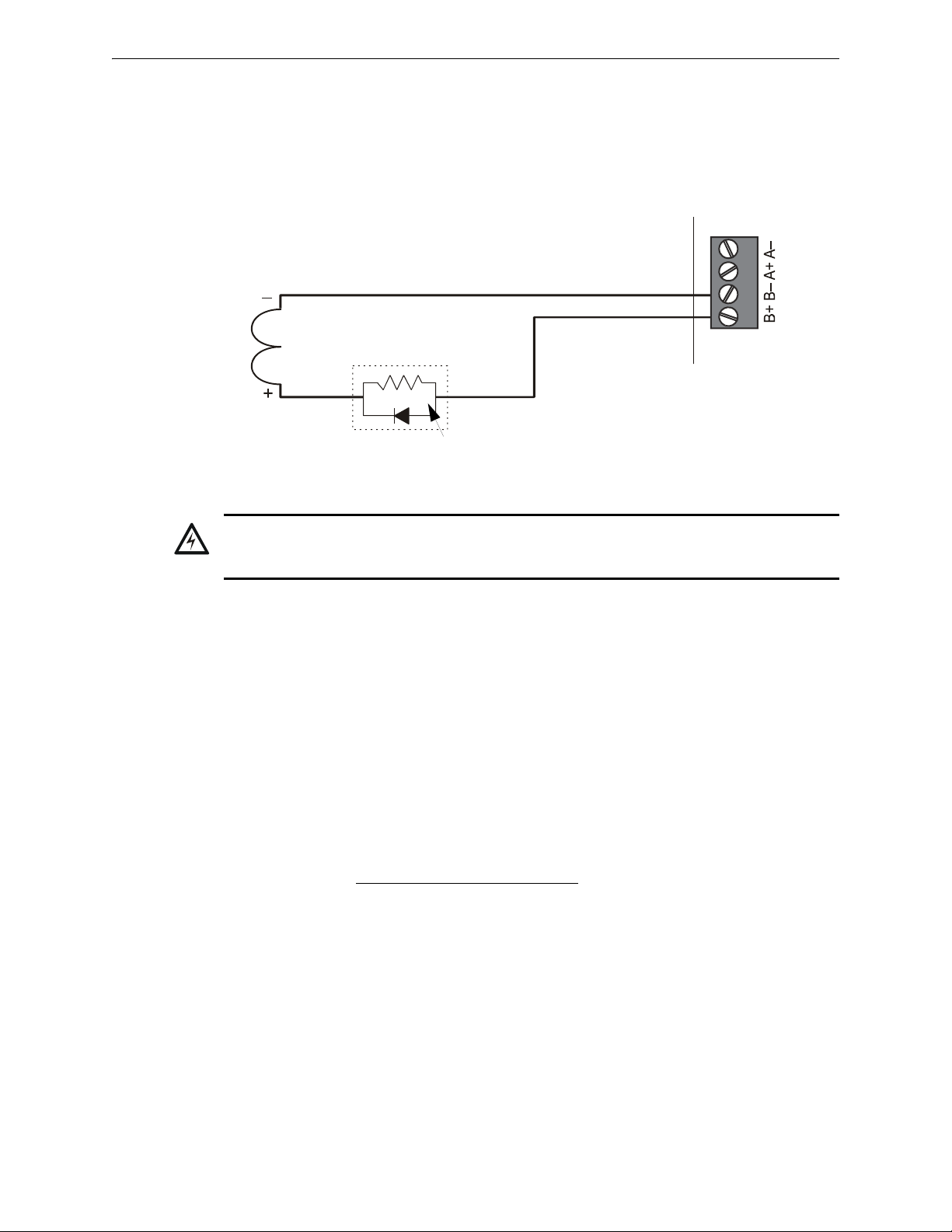
Applications Releasing Applications
!
CPU-320-RELCONN1.wmf
REL-2.2K (Use with Type Code
Rel Ckt ULC, or see Circuit
Requirement 4.)
Compatible UL-listed
24 VDC releasing device
B+ NAC/Releasing output (source)
B– NAC/Releasing output (source)
A+ Class A (return for NAC only)
A– Class A (return for NAC only)
Note: See text below for circuit requirements.
Figure 4.7 Typical Style 4 Connection of a Releasing Device to Control Panel
Control
Panel
4.7.4 Connecting a Releasing Device to the Control Panel
Use TB6 (NAC#4), TB7 (NAC#3), TB8 (NAC#2), or TB9 (NAC#1) on the control panel for
NAC⁄Releasing Circuits. The releasing circuit must be supervised and use listed, compatible
releasing devices.
WARNING:
Do not enable the BACKUP option switch for any of the four Notification Appliance Circuits (NACs) if
they are used for releasing functions!
Circuit Requirements. When connecting a releasing device, note the following:
1. The control panel provides four NAC/Releasing Circuits (Style Y or Z). Each circuit can
2. Refer to the Releasing Applications appendix in the NFS-320/E/C Programming Manual for
3. For applications using power-limited circuits:
4. For applications not requiring power-limited circuits
provide 1.5 A. Total current drawn from the power supply cannot exceed 7.4 A in an alarm
condition (refer to Table A.2, “System Draw Current Calculations,” on page 54). Use
compatible UL-listed 24 VDC appliances only. For more information on compatible
appliances, refer to the Device Compatibility Document.
configuration details (such as setting the Soak Timer).
a) Use an in-line supervisory device (P/N REL-2.2K) with control panel releasing circuits.
Connect the End-of-Line device as shown in Figure 4.7.
b) Program the releasing circuit for Type Code REL CKT ULC.
c) Circuits are supervised against opens and shorts.
–
a) If the application does not require supervising the releasing device against shorts, in-line
supervisory devices (P/N REL-2.2K) are not required.
b) In non-power-limited applications, program the releasing circuit for Type Code
RELEASE CKT.
c) Limited energy cable cannot be used to wire a non-power-limited releasing device circuit
d) Maintain a 0.25 inch (6.35 mm) spacing between the non-power-limited releasing circuit
device wiring and any power-limited circuit wiring.)
44 NFS-320/E/C Installation Manual — P/N 52745:M2 7/1/14
Page 45
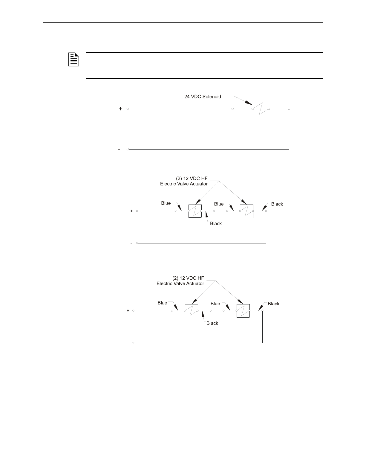
Releasing Applications Applications
IQActuatorsa.wmf
IQActuatorsb.wmf
IQActuatorsb.wmf
5. The releasing circuit must be programmed with a releasing type code listed in the NFS320/E/C Programming Manual.
NOTE: As per UL 864 9th Edition, a supervisory signal must be indicated at the panel whenever
a releasing circuit is physically disconnected. Use a monitor module to monitor dry contacts off the
switch. See 4.11.
Figure 4.8 Releasing Circuits (Option 1)
Figure 4.9 Releasing Circuits (Option 2)
Figure 4.10 Releasing Circuits (Option 3)
NFS-320/E/C Installation Manual — P/N 52745:M2 7/1/14 45
Page 46
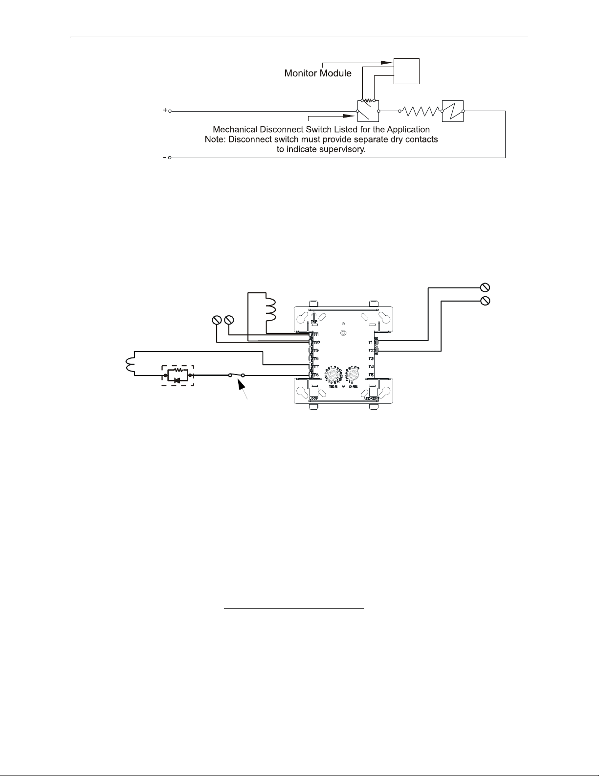
Applications Releasing Applications
GasDisconnect.wmf
–
+
–
Compatible UL-listed
24 VDC releasing device
REL-47K
(Use with Type Code
Rel Ckt ULC,
or see Circuit
Requirement 3.)
Brown Red
Non-resettable
24 VDC Power
Power Supervision
Relay (EOLR-1)
Relconn-fcmtpH.wmf
+ –
FCM-1
–
+
SLC from FACP
Note: See text for circuit requirements.
N.C. Supervision
Relay Contact
Part of EOLR-1
*If the SLC device does
not match the one in this
figure, refer to the SLC
manual appendix, which
contains wiring conversion
charts for type V and type
H modules.
Figure 4.12 Typical Connection of a 24 VDC Releasing Device to the FCM-1 Module
)
Figure 4.11 Release Circuits (Mechanical Disconnect Switch)
4.7.5 Connecting a Releasing Device to the FCM-1 Module
The module can control 1 A of current. Make sure to keep total system current within the limits of
the power supply. You can power the module from the power supply of the Control Panel or any
UL/ULC listed 24 VDC regulated power-limited power supply for Fire Protective Signaling. For
more information, refer to the Device Compatibility Document.
46 NFS-320/E/C Installation Manual — P/N 52745:M2 7/1/14
Circuit Requirements When connecting a releasing device to the FCM-1 module, note the
following:
1. Refer to the Releasing Applications appendix in the NFS-320/E/C Programming Manual for
configuration details (such as setting the Soak Timer).
2. For applications using power-limited circuits:
a) Use an in-line supervisory device (P/N REL-47K) with the FCM-1 module. Connect the inline supervisory device as shown in Figure 4.12.
b) Program the releasing circuit for Type Code REL CKT ULC.
c) Circuits are supervised against opens and shorts.
3. For applications not requiring power-limited circuits
a) In-line supervisory devices (P/N REL-47K) are not required; however, the releasing device
circuit is not supervised against shorts.
b) In non-power-limited applications, program the releasing circuit for Type Code
:
RELEASE CKT.
Page 47
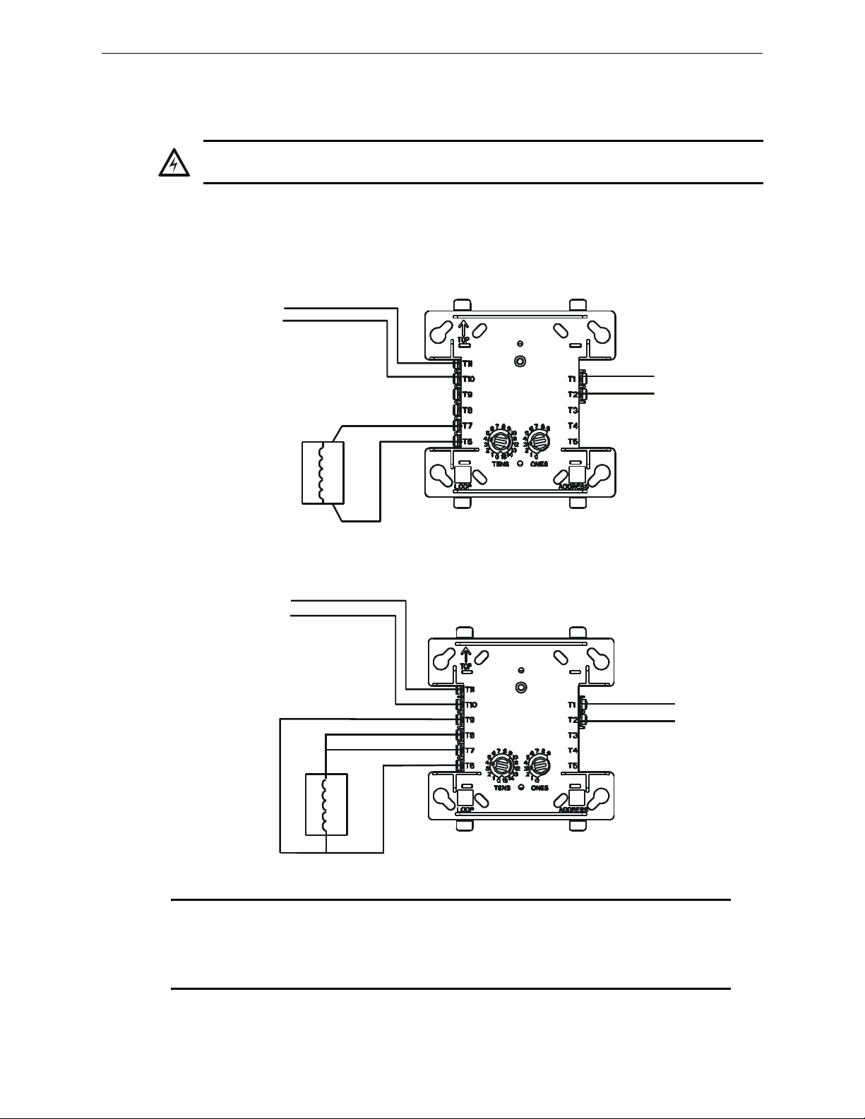
Releasing Applications Applications
!
SLC (-)
SLC (+)
Non-resettable
24 VDC power
(-)
(+)
Compatible UL-listed
24 VDC releasing device.
One (1) device maximum.
Module polarities are shown in alarm condition.
All wiring shown is supervised and power-limited.
Figure 4.13 NPFA Style Y (Class B) Wiring of the FCM-1-REL
Compatible UL-listed
24 VDC releasing device.
One (1) device maximum.
Non-resettable
24 VDC power
SLC (-)
SLC (+)
(-)
(+)
Figure 4.13 NPFA Style Z (Class A) Wiring of the FCM-1-REL
Module polarities are shown in alarm condition.
All wiring shown is supervised and power-limited.
FCM-1-REL
FCM-1-REL
When using the FCM-1-REL for
Style Y (Class B) applications,
remove jumper J1.
fcm-1-rel-y.wmf
fcm-1-1rel-z.wmf
NOTE: With software version 12.0 or higher ALL new FlashScan Mode SLC releasing
applications require the FCM-1-REL control module. The V-type FCM-1 control module may be
used in SLC releasing applications with software version 12.0 or higher. H-type FCM-1 control
modules do not support FlashScan Mode releasing applications with software version 12.0 or
higher. Use H-type FCM-1 for CLIP mode releasing applications.
c) Limited energy cable cannot be used to wire a non-power-limited releasing device circuit.
d) Maintain a 0.25 inch (6.35 mm) spacing between the non-power-limited releasing circuit
device wiring and any power-limited circuit wiring.
WARNING:
The XP6-C is not listed for releasing applications and cannot be substituted for FCM-1.
4.7.6 Connecting a Releasing Device to the FCM-1-REL
Typical Connections Figure 4.13 shows typical connections for wiring a releasing device to the
FCM-1-REL. Refer to the Device Compatibility Document for compatible releasing devices.
NFS-320/E/C Installation Manual — P/N 52745:M2 7/1/14 47
Page 48
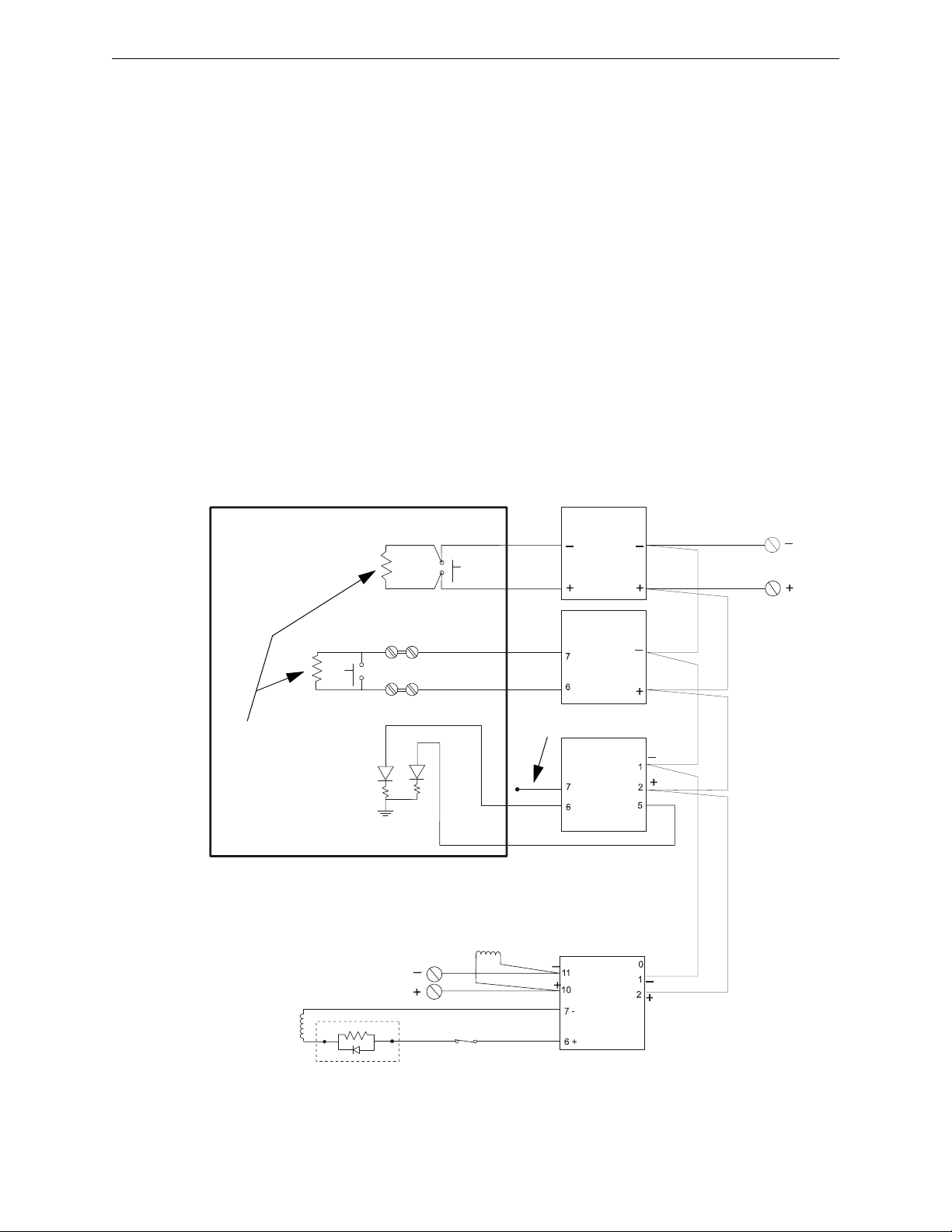
Applications Releasing Applications
SLC loop to
FACP
FCM-1
FRM-1
FMM-1
FMM-101
Black
Red
Yellow
Violet
Black
Red
Non-resettable +24 VDC
from main power supply
Manual Abort
Manual Release
Normal
Release
NBG-12LRA
See Document 51369
for installation details.
ELR mode R-47K
supervised and
power-limited
RedBrown
24 VDC UL-listed
releasing device
C.
N.O.
REL-47K
(use with Type Code
Rel Ckt ULC)
NFS640-NBG12LRAtpH.wmf
System
Common (–)
24 VDC power
from FACP’s
main power supply
N.C.
Power Supervision
Relay (EOLR-1)
N.C. Supervision
Relay Contact
Figure 4.14 Typical Connections for an NBG-12LRA Agent Release-Abort Station
Polarity shown in
an energized
state.
*If the SLC device does
not match the one in this
figure, refer to the SLC
manual appendix, which
contains wiring conversion charts for type V and
type H modules.
Critical Requirements. When connecting a releasing device to the FCM-1-REL module, note
the following:
1. See “Power Considerations” on page 52 for information on monitoring 24 VDC power.
2. Do not T-tap or branch a Style Y or Style Z circuit.
3. Only one (1) 24V solenoid or two (2) 12V solenoids in series can be connected to the FCM-1REL.
4. Do not loop wiring under the screw terminals. Break the wire run to provide supervision of
connections.
5. All applications using the FCM-1-REL are power-limited:
a. Program the releasing circuit for Type Code REL CKT ULC or RELEASE CKT.
b. Circuits are supervised against opens and shorts.
6. Refer to the NFS-320/E/C Programming Manual for instructions on setting the Soak Timer.
The FCM-1-REL module must be programmed with the correct releasing type code listed in the
NFS-320/E/C Programming Manual.
4.7.7 Connecting an NBG-12LRA Agent Release-Abort Station
48 NFS-320/E/C Installation Manual — P/N 52745:M2 7/1/14
Page 49

Releasing Applications Applications
NOTE: If using the on-board NACs, see Circuit Requirements for Section 4.7.4 “Connecting a
Releasing Device to the Control Panel” on page 44. If using FCM-1, see Circuit Requirements for
Section 4.7.5 “Connecting a Releasing Device to the FCM-1 Module” on page 46.
NFS-320/E/C Installation Manual — P/N 52745:M2 7/1/14 49
Page 50

Section 5: Testing the System
Continued on next page...
!
5.1 Acceptance Test
When finished with the original installation and all modifications, conduct a complete operational
test on the entire installation to verify compliance with applicable NFPA standards. Testing should
be conducted by a factory-trained fire alarm technician in the presence of a representative of the
Authority Having Jurisdiction and the owner’s representative. Follow procedures outlined in NFPA
Standard 72’s section on Inspection, Testing and Maintenance.
5.2 Periodic Testing and Service
Periodic testing and servicing of the control panel, all initiating and notification devices, and any
other associated equipment is essential to ensure proper and reliable operation. Test and service the
control panel according to the schedules and procedures outlined in the following documents:
• NFPA Standard 72’s section on Inspection, Testing and Maintenance.
• Service manuals and instructions for the peripheral devices installed in the system. Correct any
trouble condition or malfunction immediately.
5.3 Operational Checks
Between formal periodic testing and servicing intervals, the following operation checks should be
performed monthly, or more frequently when required by the Authority Having Jurisdiction.
• Before proceeding: a) notify the fire department and the central alarm receiving station if
transmitting alarm conditions; b) notify facility personnel of the test so that alarm sounding
devices are disregarded during the test period; and c) when necessary, disable activation of
alarm notification appliances and speakers to prevent their sounding.
• Disconnect all releasing devices to prevent accidental activation in accordance with NFPA
2001 and NFPA 12A releasing agents.
WARNING:
Do not rely on disable/enable software settings to lockout releasing devices.
• Check that the green POWER LED lights.
• Check that all status LEDs are off.
• Press and hold the LAMP TEST key. Verify that all LEDs and all LCD display segments work.
• Activate an Initiating Device Circuit using an alarm initiating device or an addressable
initiating device on the SLC and check that all programmed active notification appliances
function. Reset the alarm initiating device, the control panel, and any other associated
equipment. Select the paging function and confirm that the message can be heard in the
affected fire zones. Repeat the above step with each Initiating Device Circuit and each
addressable device.
• Remove AC power, activate an Initiating Device Circuit through an alarm initiating device or
an addressable initiating device on the SLC, and check that programmed active notification
appliances sound, and alarm indicators illuminate. Measure the battery voltage with
notification appliances active. Replace any battery with a terminal voltage less than 21.6 VDC
and reapply AC Power
50 NFS-320/E/C Installation Manual — P/N 52745:M2 7/1/14
Page 51
Battery Checks and Maintenance Testing the System
!
!
.
NOTE: The battery test requires fully charged batteries. If batteries are new or discharged due
to a recent power outage, allow the batteries to charge for 48 hours before testing.
• Return all circuits to their pretest condition.
• Check that all status LEDs are off and the green POWER LED is on.
• Notify fire, central station and/or building personnel when you finish testing the system.
5.4 Battery Checks and Maintenance
Maintenance-free sealed lead-acid batteries used in the system do not require the addition of water
or electrolyte. These batteries are charged and maintained in a fully charged state by the main
power supply’s charger during normal system operation. A discharged battery typically reaches the
voltage of 27.6 VDC within 48 hours; the charge rate depends on the battery size (2.0A for 1826AH; 5.0A-5.7A for 26AH-200AH).
Immediately replace a leaking or damaged battery. Batteries should be replaced in accordance with
the battery manufacturer’s recommendations.
WARNING:
Batteries contain Sulfuric Acid which can cause severe burns to the skin and eyes and damage to
fabrics.
• If a battery leaks and contact is made with the Sulfuric Acid, immediately flush skin and/or
eyes with water for at least 15 minutes. Water and household baking soda provides a good
neutralizing solution for Sulfuric Acid.
• If Sulfuric Acid gets into eyes, seek immediate medical attention.
• Ensure proper handling of the battery to prevent short circuits.
• Take care to avoid accidental shorting of the leads from uninsulated work benches, tools,
bracelets, rings, and coins.
WARNING:
Shorting the battery leads can damage the battery, equipment, and could cause injury to personnel.
NFS-320/E/C Installation Manual — P/N 52745:M2 7/1/14 51
Page 52

Appendix A: Power Supply Calculations
Calculations must be done to determine standby and alarm DC current loads. Ampere-hour
requirements must be calculated as well to determine battery size.
The CPS-24/E power supply provides filtered 24VDC power that may be used for operating
external devices. Use Table A.2 to determine if external loading is within the capabilities of the
power supply.
A.1 Calculating AC Branch Circuit Current
Use Table A.1 below to determine the total amount of current, in AC amperes, that a 120 VAC,
50/60 Hz service must be able to supply to the fire alarm system. Devices rated for 220-240 VAC
operation will draw approximately one-half the current listed in Table A.1.
Device Type No. of Devices Current (amps) Total Current
CPS-24 Power Supply [ 1 ] X 5.0 = 5.0
CPS-24/E Power Supply [ ] X 2.5 =
FCPS-24S6/S8 [ ] X 3.2 =
ACPS-2406 [ ] X 2.7
ACPS-610 [ ] X 5.0
ACPS-610/E [ ] X 2.5
APS-6R [ ] X 2.5 =
CHG-120 [ ] X 2.0 =
Sum column for AC Branch Current required=amps
*
*
*
=
=
=
Table A.1 120 VAC Fire Alarm Circuit
* Separate calculations are required for any devices powered by the ACPS-
610 or ACPS-2406. They have their own integral battery charger and
batteries can be connected directly to them. Refer to the ACPS-2406 or
ACPS-610 Installation Manuals for battery calculations.
AC Branch Circuit Installation
For guidelines on wiring the AC branch circuit current, see “Operating Power: AC Branch Circuit”
on page 60 in Appendix B.1 “Electrical Specifications”.
A.2 Calculating the System Current Draws
The control panel’s main power supply must be able to power all internal system devices (and
several types of external devices) continuously during non-fire alarm conditions. Use column 1 in
Table A.2 to calculate the Non-Fire Alarm Load on the power supply regulator when applying
primary power. The main power supply must also provide a finite amount of additional current
during a fire alarm condition. Use column 2 in Table A.2 to calculate the additional current needed
during fire alarms. The requirements for non-fire alarm and fire alarm current loads cannot exceed
the capabilities of the power supply as listed below:
• 3.9 A at 24 VDC during Standby; and
• 7.4 A at 24 VDC during Alarm.
The current draw from all NACs plus DC output from TB10 and TB2 is 3.0 A during standby, and
6.0 A in alarm.
52 NFS-320/E/C Installation Manual — P/N 52745:M2 7/1/14
Page 53

Calculating the System Current Draws Power Supply Calculations
How to Use the Calculating Tables
As used in this section, “Primary” refers to the control panel’s on-board power supply, its primary
source of AC power. “Secondary” refers to the control panel’s backup batteries (or any other 24
VDC power supply listed for Fire Protective Signaling and connected in place of the batteries). The
term “standby” refers to the output current required when no fire alarm is present. The term “alarm”
refers to the output current required when a fire alarm is present.
The Primary Power Source Non-Alarm Current and Alarm Current columns are DC current
calculations. These calculations confirm that the power supply can provide enough current to
support the system during Primary Non-Fire Alarm and Fire Alarm conditions.
Quantities List the number of devices powered by the FACP and its power supply. Devices
powered by the Accessories Output (TB10 and TB2) draw current directly from the panel. Devices
powered by the Panel Output draw current through the fire panel’s connection to the power supply.
Use these quantities to calculate total current draw of each set of devices in calculation columns 1,
2, and 3.
Calculation Column 1 (Primary, Non-Fire Alarm Current in amps) Add the contents of
calculation column 1 to get the current drawn from the power supply during a non-alarm condition,
with AC power applied. This current draw cannot exceed 3.9 A without an auxiliary power supply.
Calculation Column 2 (Primary, Fire Alarm Current in amps) Calculation column 2 lets
the system designer determine the current load that the power supply must support during a fire
alarm. The total current draw during a fire alarm cannot exceed 7.4 A without an auxiliary power
supply.
Typically, a system should contain capacity to activate all output circuits and relays, and support
fire alarms on no less than 10% of Initiating Device Circuits, subject to the requirements of the
Authority Having Jurisdiction (AHJ).
The Control Panel provides power for Notification Appliance Circuits. Refer to the Device
Compatibility Document for 24 VDC notification appliances that are UL- and ULC-listed for fire
alarm systems.
Calculation Column 3 [Secondary (Battery) Non-Alarm Current] Column 3 lets the
system designer calculate the non-fire alarm current drawn from the secondary source in a non-fire
alarm condition during AC power loss.The non-fire alarm current is required to complete the
standby battery calculations. After summing all current draws, insert the total in Table A.3.
NFS-320/E/C Installation Manual — P/N 52745:M2 7/1/14 53
Page 54
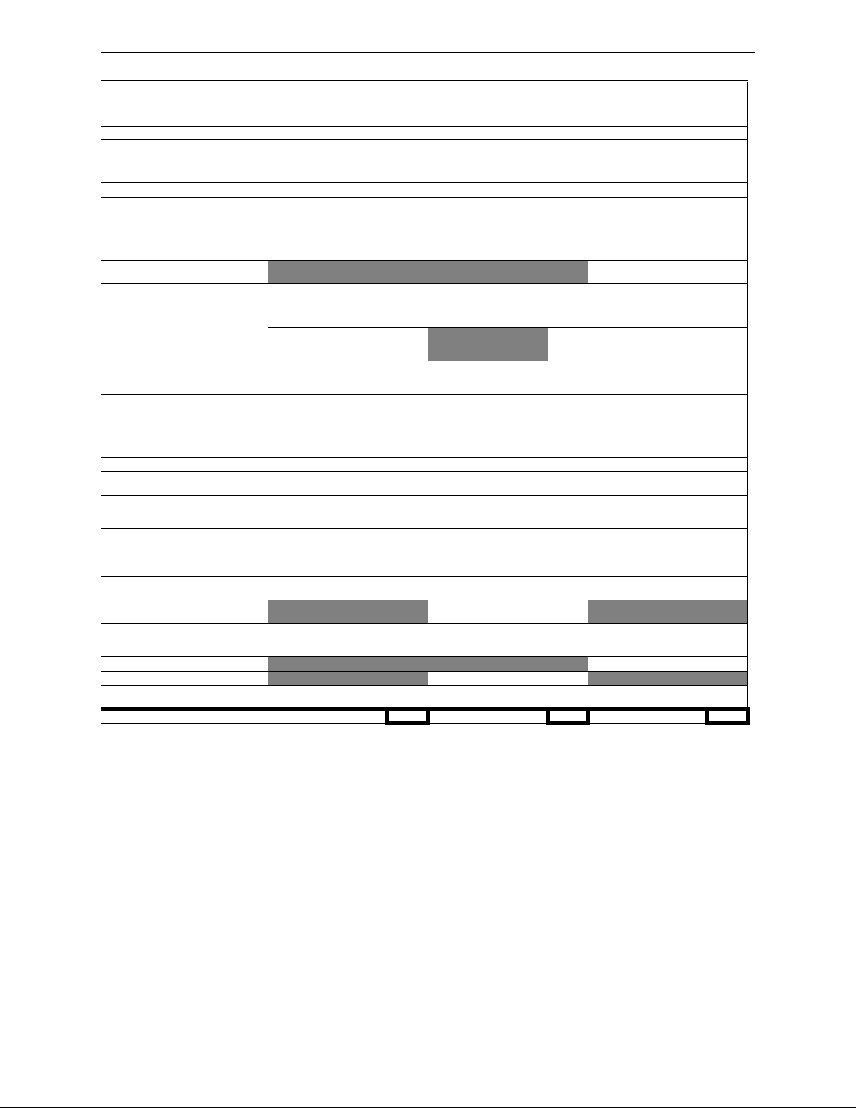
Power Supply Calculations Calculating the System Current Draws
Category
Primary, Non-Fire Alarm
Current (amps)
Calculation Column 1
NFS-320/E
# NACs in use (0, 1, 2, 3 or 4)
CPS-24/E
KDM-R2 (Backlight on)
SLC loop†: 1 x [0.200]= 1 x [0.200]= 1 x [0.200]=
NCA, NCA-2 Back-light ON
NCA, NCA-2 Back-light OFF
NCM-W/F
HS-NCM-W/MF/SF/WMF/WSF/MFSF
TM-4
DPI-232 (Refer to manual**)
APS-6R
ACPS-2406, ACPS-610
ACM-24AT
ACM-48A
AEM-24AT
AEM-48A
Maximum number of LEDs illuminated on
these annunciators during non-fire
conditions:
AFM-16AT, AFM-32A
ACM-16AT, ACM-3 2A
AEM-16AT, AEM-3 2A
AFM-16A
ACM-8R (refer to manual**)
LDM (refer to manual**)
FDU-80
LCD-80
LCD2-80
FZM-1, MMX-2 Auxiliary power [ ] x [0.0115]= [ ] x [0.090]= [ ] x [0.0115]=
RPT- W, R PT- WF, RP T-F
RPT-485W, RPT-485WF
UDACT Communicator
UDACT-2 Communicator
NFV-25/50 (see manual**)
FWSG (only if powered by the FWSG 24V
connections TB:A2 and TB:A3)
Four-Wire Smoke Detectors‡ [][]x [ ]=
Power Supervision Relay
EOLR-1
Notification Appliance powered from Main
Power Supply
DHX-501, FSD-751RPFSD-751RPL(Duct
Detectors with internal relays)
Refer to installation document
CHG-120 Battery Charger [ ] x [0.060]=
Local Energy Municipal Box [ ] x [ ]=
Compatible Devices not listed above†† [][]x [ ]=
Sum each column for totals Primary, non-alarm: Primary, alarm: Secondary, non-alarm:
**
*
Qty X [current draw]= Total Qty X [current draw]= Total Qty X [current draw]= Total
1
x [0.250] =
[]
x [0.035]
n/a
n/a
[]
x [0.100]=
[]
x [0.400]=
[]
x [0.200]=
[]
x [0.110]=
[]
x [0.400]=
[]
x [0.110]=
[]
x [ ]=
[]
x [0.016]=
[]
x [0.016]=
[]
x [0.002]=
[]
x [0.002]=
[ ] x [0.0054]= [ ] x [0.0054]=
[]
x [0.040]=
[]
x [0.040]=
[]
x [0.002]=
[]
x [0.025]=
[]
x [ ]=
[]
x [ ]=
[]
x [0.0643]=
[]
x [0.100]=
[ ] x [0.017]= [ ] x [0.017]= [ ] x [0.017]=
[]
x [0.040]=
[]
x [0.052]=
[]
x [ ]=
[ ] x [0.040]= [ ] x [0.040]= [ ] x [0.040]=
x [ ]=
[ ] x [0.020]= [ ] x [0.020]= [ ] x [0.020]=
[][]x [ ]=
x [ ]=
x [ ]=
Calculation Column 2
Primary, Fire Alarm
Current (amps)
1
x [0.250] =
[]
x [0.035]
n/a
n/a
[]
x [0.100]=
[]
x [0.400]=
[]
x [0.200]=
[]
x [0.110]=
[]
x [0.400]=
[]
x [0.175]=
[]
x [ ]=
[]
x [0.070]=
[]
x [0.070]=
[]
x [0.056]=
[]
x [0.056]=
[]
x [0.056]=
[]
x [0.056]=
[]
x [0.018]=
[]
x [0.065]=
[]
x [ ]=
[]
x [ ]=
[]
x [0.0643]=
[]
x [0.100]=
[]
x [0.100]=
[]
x [0.087]=
[]
x [ ]=
[][]x [ ]=
x [ ]=
[][]x [ ]=
x [ ]=
[][]x [ ]=
x [ ]=
[][]x [ ]=
x [ ]=
Calculation Column 3
Secondary, Non-Fire Alarm
Current (amps)
1
x [0.250] =
[]
x [0.035]
1
x [0.040]
[]
x [0.100]=
[]
x [0.400]=
[]
x [0.200]=
[]
x [0.110]=
[]
x [0.400]=
[]
x [0.110]=
[]
x [ ]=
[][]x [0.025]=
x [0.0013]=
[]
x [0.016]=
[]
x [0.016]=
[]
x [0.002]=
[]
x [0.002]=
[]
x [0.040]=
[]
x [0.040]=
[]
x [0.002]=
[]
x [0.025]=
[]
x [ ]=
[]
x [ ]=
[]
x [0.0643]=
[]
x [0.050]=
[]
x [0.040]=
[]
x [0.052]=
[]
x [ ]=
[][]x [ ]=
x [ ]=
[][]x [ ]=
x [ ]=
[][]x [ ]=
x [ ]=
Table A.2 System Draw Current Calculations
* Maximum current draw for all NACs plus DC output from TB10 and TB2 is 3.0 A during standby.
† Value represents an SLC’s maximum current draw. Refer to device datasheets for individual current draws.
‡ The total regulated load current supplied to four-wire smoke detector and power supervision relays cannot exceed 1.25 A.
** Enter the total notification appliance draw from the Main Power Supply, excluding the current from APS-6R supplies. Refer to Device Compatibility Document.
†† Refer to manual and/or Device Compatibility Document. See Table 1.1, “Reference Documentation,” on page 8 for specific documentation part numbers.
54 NFS-320/E/C Installation Manual — P/N 52745:M2 7/1/14
Page 55
Calculating the System Current Draws Power Supply Calculations
A.2.1 Calculating the Maximum Secondary Power Fire Alarm
Current Draw
Use Table A.3 below to determine the maximum current requirements of secondary power source
during fire alarm conditions. The result obtained is the amount of current that the batteries must be
able to supply to the fire alarm system. Use the result in Table A.4 to determine the size of the
batteries needed for the fire alarm system.
Results taken from Table A.3 below assume that, while in a fire alarm condition, batteries must
feed the main power supply (and any additional supplies such as the APS2-6R) with the maximum
rated power each supply can provide.
Device Quantity
Alarm Current, from Table A.2, col 2 =
APS2-6R
Sum Column for Secondary Fire Alarm Load =
*
[] X 6 =
Current
(in amps)
Table A.3 Maximum Secondary Power Fire Alarm Current Draw
* Actual load current may be used in place of maximum rated supply
current. To calculate actual load current, sum the current draws for each
appliance connected to APS-6R supplies.
Total Current/Type
NOTE: The Secondary Fire Alarm Load cannot exceed the following:
• 12 A with BAT-12260 batteries (12 V, 26 AH).
• 20 A with BAT-12550 batteries (12 V, 55 AH).
NFS-320/E/C Installation Manual — P/N 52745:M2 7/1/14 55
Page 56

Power Supply Calculations Calculating the Battery Requirements
A.3 Calculating the Battery Requirements
A.3.1 Calculating the Battery Capacity
Use this table to determine the battery capacity needed for the system:
Current (amps) X Time (hours) = AH
Secondary Non-Fire Alarm Current
(from column 3 in Table A.2)
(see Note 8)
________________
APS-6R
Standby Load Current
Required Secondary Non-Fire Alarm
Standby Time (24 or 60 hours)
X
________________ = _________AH
Required Secondary Non-Fire Alarm
Standby Time (24 or 60 hours)
________________ X
Secondary Fire Alarm Load
(from Table A.3)
(see Note 8)
________________ X
Sum Column for Total Secondary Amp Hours calculated = _________AH
Multiply by the derating factor x 1.2 (see Note 7) = _________AH
Battery Size – Total Secondary Amp Hours Required = _________AH
1. NFPA 72 Local, Proprietary, and Central Station systems requires 24 hours of standby power followed by
5 minutes in alarm.
2. NFPA 72 Auxiliary and Remote Station Systems require 24 hours of standby power followed by 5 minutes
in alarm.
3. Batteries installed in a system powered by an automatic starting engine generator need to provide at
least 4 hours of standby power.
4. Factory Mutual requires 90 hours of standby for deluge-preaction systems.
5. Emergency voice/alarm communications systems require 2 hours of operation in the alarm condition.
Due to the sporadic nature of voice operation, however, NFPA 72 permits 15 minutes of operation at a
maximum connected load to equal 2 hours of normal use.
6. If the total exceeds 26 AH, the system requires a separate NFS-LBB, BB-100 or BB-200 battery
enclosure for two larger capacity batteries.
7. The following battery derating factors must be used for Canadian installations using NFS-320C charger:
• For a 26 AH battery, use derating factor of 1.5
• For a 55 AH battery, use derating factor of 1.8
• For a 100 AH battery, use derating factor of 2.5
• For a 200 AH battery, use derating factor of 2.5
8. For 26 AH batteries: maximum standby current cannot exceed 0.65A; maximum alarm current cannot
exceed 6.75A
________________ = _________AH
Required Fire Alarm Standby Time:
(for 5 minutes, enter 0.084; for 15
minutes, enter 0.25)
________________ = _________AH
Table A.4 Secondary Power Standby and Fire Alarm Load
56 NFS-320/E/C Installation Manual — P/N 52745:M2 7/1/14
Page 57

Calculating the Battery Requirements Power Supply Calculations
A.3.2 Calculating the Battery Size
Use this table to choose the battery size, in amp-hours, needed to support the fire alarm system.
The CPS-24/E can charge batteries from 18 to 200 AH. Select batteries that meet or exceed the
Total Amp-Hours calculated in Table A.4 and that are within the acceptable battery charger range.
Write the amp-hours requirements on the Protected Premises label.
The maximum battery size that can be mounted inside the NFS-320’s cabinet is 26AH.
Battery Size
18 AH 12 volts two BAT-12180 NFS-320 enclosure, BB-25
26 AH 12 volts two BAT-12260 NFS-320 enclosure, BB-25
100 AH 12 volts four for 100 AH
*Manufactured to our specifications.
†
Red version available; add “R” to part number listed here
Voltage
Rating
Number
Required
two for 200 AH
Part
Number*
BAT-121000 BB-100
Backbox Part Number
BB-200
Table A.5 Selecting Battery and Battery Backbox
†
NFS-320/E/C Installation Manual — P/N 52745:M2 7/1/14 57
Page 58
Appendix B: Electrical Specifications
B.1 Electrical Specifications
AC Power
Component Values
Main Power Supply 120 VAC, 50/60 Hz, 5.0 A; or
220-240 VAC, 50/60 Hz, 2.5 A
Wire size Maximum 12 AWG (3.31 mm
NOTE: If using an auxiliary power supply such as FCPS-24S6/S8 or APS-6R, refer to the
documentation for that equipment.
Batteries
The control panel uses only sealed lead-acid batteries for secondary standby power. Maximum battery capacity for the CPS-24/E main power supply is 200 AH. The NFS-320 enclosure provides
space for up to two 26 AH batteries. Use external battery boxes if the installation requires larger
capacity batteries; see Table A.5, “Selecting Battery and Battery Backbox,” on page 57.
When AC Power is lost, the deeply-discharged battery cutoff protection will be invoked at 17 volts.
The power supply will be disconnected from the batteries. The power supply’s normal operation
will be restored when AC power returns.
2
) with 600 VAC insulation
The table below contains battery charger specifications.
Charger Description Specifications
CPS-24/E
Main Power Supply
CHG-120
Battery Charger
ACPS-2406
Auxiliary
Charger/Power
Supply
ACPS-610
Addressable
Charger/Power
Supply
An internal battery charger
for 18 AH to 200 AH
An external battery charger
designed to charge lead-acid
batteries between 26 AH and
120 AH
An internal battery charger
for 7 AH to 26 AH
An internal battery charger
for 12 AH to 200 AH
Normal Charge: 27.6 VDC +/- 0.24 VDC
Charging Current: 2.0 A or 5.7 A (Software selectable)
Dual Rate: High Charge: 28.1 VDC
Normal Charge: 27.6 VDC
Charging Current: 4.5 A
Normal Charge: 27.6 VDC
Charging Current: 1.1 A max (0.750 A typical)
Normal Charge: 27.6 VDC +/- 0.24 VDC
Charging Current: 2A, 5A, or OFF
(Software Selectable)
Signaling Line Circuit (SLC)
Item Value
Voltage 24 VDC nominal, 27.6 VDC maximum
Maximum length 12,500 ft. (3810 m) total loop length (NFPA Style 4, 6, and 7)
Note: Refer to Appendix B.2 “Wire Requirements” for limitations.
Maximum current 400 mA peak, (max short circuit; circuit will shut down until short is fixed). For
battery calculations use 200mA.
Maximum resistance 50 ohms (supervised and power-limited)
58 NFS-320/E/C Installation Manual — P/N 52745:M2 7/1/14
Page 59

Electrical Specifications Electrical Specifications
Notification Appliance Circuits and Releasing Circuits
Item Value
Max. wiring voltage drop 2 VDC
NAC Nominal operating
voltage
Special Applications for
Releasing Circuits
Current for all external
devices connected to the
control panel’s power supply
Optional ACPS-2406 Total 6 A in alarm (5 A continuous)
Optional ACPS-610 Total 6 A in alarm (1.5 A single output)
Optional APS-6R Total 6 A in alarm (4 A continuous)
Maximum signaling
current/circuit per NAC
End-of-Line Resistors
(ELRs)
NOTE: For a list of compatible Notification Appliance Circuits and Releasing Circuits see Notifier Device
Compatibility Document 15378.
(Retrofit note: SLCs with old CMX modules are restricted to 1.2 VDC.)
24 VDC regulated; 1.5 A max.
20.16 - 26.42 VDC
7.4 A in alarm (3.9 A continuous)
TB10 and all 4 NACs share a maximum of 3.0 A in standby and 6.0 A in alarm.
1.5 A
Note: Some devices have maximum draws less than this; refer to the device’s
documentation.
Control Panel NACs (TB6, TB7, TB8, TB9): 2.2K, 1/2 watt
XP6-C, FCM-1 Modules: 47K, 1/2 watt
Output Relays (common)
Output relays for Alarm and Trouble are common on TB4; Supervisory, and Security are programmable on TB5. See Figure 3.11, “Form-C Relay Connections” on page 27).
Contact ratings: 2.0 A @ 30 VDC (resistive)
Four-wire Smoke Detector Power
Control Panel terminals TB10 RESET (+) and (–) supply filtered, low-noise power for four-wire
smoke detectors. Specifications are:
• Nominal voltage: 24 VDC special applications.
• Maximum rated current: 1.25 A DC
• Maximum ripple voltage: 176 mVrms
• TB10 and all 4 NACs share a maximum of 3.0 A in standby and 6.0 A in alarm.
Refer to the Device Compatibility Document for compatible 24 VDC detectors.
Power Output
Control Panel terminals TB10 NONRESET (+) and (–) supply one (1) power-limited circuit available to power external devices, such as notification appliances and annunciators.
• Nominal voltage: 24 VDC regulated, special applications, 1.5 A max.
• Maximum rated current: 1.25 A DC
• Maximum ripple voltage: 176 mVrms
• TB10, TB2, and all 4 NACs share a maximum of 3.0 A in standby and 6.0 A in alarm.
Refer to the Device Compatibility Document for compatible devices and notification appliances.
NOTE: The Control Panel provides a total of 7.4 A of power in alarm (3.9 A in standby), shared
by all internal circuitry and external provisions (24 V resettable and non-resettable). TB10 and all
4 NACs share a maximum of 3.0 A in standby and 6.0 in alarm. For power requirements, refer to
the power supply calculation tables in Appendix A.
NFS-320/E/C Installation Manual — P/N 52745:M2 7/1/14 59
Page 60

Electrical Specifications Wire Requirements
Operating Power: AC Branch Circuit
The control panel requires connection to a separate dedicated AC branch circuit. Follow these
guidelines when connecting the AC branch circuit:
• Label the branch circuit “Fire Alarm”. This must be a separate dedicated AC fire alarm circuit.
• Connect the branch circuit to the line side of the main power feed of the protected premises.
• Do not power other equipment from the fire alarm branch circuit.
• Run the AC branch circuit wire continuously, without any disconnect devices except for
overcurrent protection, from the power source to the fire alarm control panel.
• Overcurrent protection for the AC branch circuit must comply with Article 760 of the National
Electrical Codes, as well as local codes.
• Use 12 AWG (3.31 mm
Connect the ground terminal (TB1-Earth) to a solid earth ground (a metallic, cold water pipe may
be suitable in some installations). This connection is vital in reducing the panel’s susceptibility to
transients generated by lightning and electrostatic discharge.
2
) wire with 600 VAC insulation for the AC branch circuit.
Operating Power: Secondary Power Source (Batteries)
The battery charger is current-limited and can recharge sealed lead-acid type batteries. The battery
charger shuts off when the control panel is in alarm.
B.2 Wire Requirements
Each type of circuit within the Fire Alarm Control System requires use of a specific wire type to
ensure proper circuit operation. The wire gauge of a particular circuit depends on the length of that
circuit and the current traveling through it. Use Table B.1 below to determine the specific wiring
requirements for each circuit.
Compliance with the Federal Communications Commission (FCC) and Canadian Department of
Communication regulations on electrical energy radiation requires the following: Use twisted-pair
shielded wire for any non-SLC-loop wiring entering or exiting the cabinet that is not enclosed in
conduit. Use twisted-pair unshielded wiring for SLC-loop wiring.
NOTE: If running an SLC in conduit with Notification Appliance Circuits, you can reduce
problems by exclusively using electronic sounders (such as the SpectrAlert, SpectrAlert Advanced
or MA/SS-24 Series) instead of more electronically noisy notification appliances (such as
electromechanical bells or horns).
60 NFS-320/E/C Installation Manual — P/N 52745:M2 7/1/14
Page 61

Wire Requirements Electrical Specifications
Circuit Type
SLC
(power limited)
Circuit
Function
Connects to
intelligent and
addressable
modules.
Wire Requirements
Twisted-unshielded pair, 12 to 18 AWG
(3.31 to 0.82 mm
2
). 50 ohms maximum per
length of Style 6 and 7 loops. 50 ohms per
branch maximum for Style 4 loop.
Twisted-shielded pair
NOTE:
• Shields must be isolated from ground.
Distance
(feet/meters)
12,500 ft. (3,810 m)
9,500 ft. (2,895.6 m)
6,000 ft. (1,828.8 m)
3,700 ft. (1,127.76 m)
5,000 ft. (1,524 m)
3,700 ft. (1,127.76 m)
Typ i cal Wi re Type
12 AWG (3.31 mm
14 AWG (2.08 mm
16 AWG (1.31 mm
18 AWG (0.82 mm
12 to 16 AWG (3.31 to
1.31 mm
2
)
18 AWG (0.82 mm
2
)
2
)
2
)
2
)
2)
• Shields should be broken at each
device.
Untwisted, unshielded wire, in conduit or
outside of conduit.
5,000 ft. (1,524 m)
3,700 ft. (1,127.76 m)
12 to 16 AWG (3.31 to
1.31 mm
18 AWG (0.82 mm
2
)
2)
Note: Maximum total capacitance of all
SLC wiring (both between conductors and
from any conductor to ground) should not
exceed 0.5 mircofarads.
EIA-485
(power limited)
Connects to
FDU-80, ACS
modules, LCD-
Twisted-shielded pair with a characteristic
impedance of 120 ohms. 18 AWG (0.82
2
mm
) minimum.
6,000/1829
(max)
16 AWG (1.31 mm
2
)
80, or TM-4
Transmitter
EIA-232
(power limited)
Connects to
Printers, CRT,
Twisted-shielded pair in conduit.
18 AWG (0.82 mm2) minimum.
20 feet (6.1 m)
(without modem)
16 AWG (1.31 mm
2
)
or PC.
IDC
Initiating Device
Circuit
FMM-1,
FMM-101,
FDM-1, XP10-
12-18 AWG (3.31 to 0.82 mm
Maximum circuit resistance is 20 ohms.
2
).
12 to 18 AWG (3.31 to
0.82 mm
2
)
M, XP6-MA
(power limited)
NAC
Notification
Appliance
Circuit
Releasing
Module
FCM-1*, XP6-C
(power limited)
12-18 AWG (3.31 to 0.82 mm
At alarm current level, no more than a 1.2
V drop at the end of the circuit, or sized to
provide the minimum rated operating
voltage of the appliances used.
FCM-1-REL 12-18 AWG (3.31 to 0.82 mm
5 ohms maximum per circuit for class A or
class B, or sized to provide the minimum
rated operating voltage of the appliances
used.
2
).
To meet 1.2 V drop,
or sized to provide
the minimum rated
operating voltage of
the appliances used.
2
).
To meet 5 ohms
maximum current
resistance, or sized
to provide the
minimum rated
12 to 18 AWG (3.31 to
0.82 mm
12 to 18 AWG (3.31 to
0.82 mm
2
)
2
)
operating voltage of
the appliances used.
24 VDC Power
Runs
(power-limited)
To T M - 4
Transmitter,
Annunciator and
FCM-1 modules
CHG-120 External battery
12-18 AWG (3.31 to 0.82 mm
Size wire so that no more than 1.2 V drop
across wire run from supply source to end
of any branch.
12 AWG (3.31 mm
2
) in conduit 20/6.1 (max) 12 AWG (3.31 mm2)
2
).
To meet 1.2 volt drop 12 to 18 AWG (3.31 to
0.82 mm
2
)
charger
*FCM-1 can not be used for synchronized strobe/sounder applications.
Table B.1 Wire Requirements
NOTE: Lightning arresters required on circuits extending between buildings; 999 meter length
maximum to meet UL 60950.
NFS-320/E/C Installation Manual — P/N 52745:M2 7/1/14 61
Page 62

Index
Numerics
24 VDC, see Power (DC)
A
A77-716B, see Power Supervision Relay
(Replaced by EOLR-1)
AC, see Power
Acceptance Test
ACM-8R
Labeling Requirements
Agent Release-Abort Station
Alarm Relays, see Form-C Relays
23, 24
50
30
48
27
B
Backup-Alarm Switches 28
Batteries, also see Power: DC
Battery Calculations
Battery Checks and Maintenance
Battery Specifications
Connections
24
24
52, 53, 54, 55, 56, 57
51
58
C
Cabinets
Dimensions
Mounting
Central Receiving Unit, also see UDACT Manual
41
Circuit Board, see CPU
Compatible Equipment
Components
Control Panel Circuit Board, see CPU
CPS-24/E, see Power Supply
CPU
Drawing
Overview
CRTs
33
CRT/PRN Combination
CRT-2 Configuration
CRT-2 Function Keys and Parameters
Installation
15
20
16, 17
13, 14
11, 13, 14
11
33
32
33
30–34
D
DC, see Power 23, 24
E
Electrical connections 22
Electrical Specifications
Ematch Protection Device
EOLR-1, see Power Supervision Relay
External Power Supervision
58
27
36
F
FCM-1, also see Releasing Applications
Circuit Requirements
FCM-1-REL, also see Releasing Applications
Connections
Fire/Security Applications
Form-C relays
Four-wire Smoke Detector
Specifications
47
27, 59
46
47
40–42
59
I
Installation
Checklist
Preparation
19
18
J
Jumper Locations 13, 14
K
KDM-R2 11
Removal/Installation
21
L
LDM-R32
non-power-limited circuits
lockout
50
30
M
Main Power Supply, see Power Supply
Maintenance
microcontroller failure
Multiple Detector Operation
50
28
34
N
NACs (Notification Appliance Circuits)
Backup option
NAC Connections
Releasing applications
Specifications
NBG-12LRA
NCM, Also see Networking
Installation
Networking
NFPA Applications
NFPA 72 Central or Remote Station Fire
NFPA Applications (Overview)
NFS-320 (120V Operation), see Basic Equipment
Packages
11
28
59
48
20
22
Alarm System
26
26, 28, 43, 44
37
36
62 NFS-320/E/C Installation Manual — P/N 52745:M2 7/1/14
Page 63

Index O–W
NFS-320 (120V operation), see Basic Equipment
Packages
NFS-320 (120Voperation), see Basic Equipment
Packages
NFS-320E (220-240V Operation)
Nonpower-limited circuits
Notification Appliance Circuits, see NACs
13
14
UL wiring requirements
11
29, 30
O
Operating Power 60
Operational Checks
Option boards
Installation steps
Output relays
Connections
Specifications
50
20
27, 59
59
P
Periodic Testing 50
Power
AC Power Checklist
AC Power Connections
AC power connections
AC specifications
DC Power Connections
DC power connections
Installation steps
Non-resettable
Power specifications
Resettable
Power Supervision Relay
power supply
Power Supply Calculations
Power supply calculations
Power-limited Wiring Requirements
Printers
33
Installation
PRN series connections
PRN settings
PRN/CRT Combination
Remote PRN
Proprietary Security Alarm Applications
Wiring
Protected Premises Unit
24
12
30–34
32
31
42
23
23, 24
23
58
23, 24
24
22
25
22, 59
48
52, 54, 55, 56, 57
53
29
31
33
37
Connections
FCM-1-REL Connections
44
47
S
Security Relays, see Form-C Relays 27
Security Tamper Switch
Service
50
SLC
Device Capacity
Installation
Maximum Wiring Distance
specifications
SLC See also SLC Wiring Manual
Specifications
Standard equipment
Stat-X
Device Wiring
STS-1, also see Security Tamper Switch
Supervisory and Security contacts
configuring as Alarm contacts
Supervisory Relays, see Form-C Relays
Supplemental Documentation
Switches
Backup-Alarm
Switch Locations
System
Description of features
Limitations
Options
System Current Draws
System current draws
35
58, 59
11
41, 42
34
34
58
34
11
27
42
27
27
8
28
14
10
11
52, 54, 55, 56, 57
53
T
Terminal Block Locations 13, 14
Testing
50
TM-4
see TM-4 Transmitter Module Installation
Document
Trouble Relays, see Form-C Relays
21
27
U
UDACT also see Central Receiving Unit
and the UDACT Manual
UL nonpower-limited wiring requirements
UL Requirements
29
37
29
R
Related Documentation 8
Relays, see Form-C Relays
Releasing Circuits
Connections
Releasing Applications
Specifications
Releasing Device
Circuit Requirements
NFS-320/E/C Installation Manual — P/N 52745:M2 7/1/14 63
26
27
43–49
59
44
V
VeriFire 35
W
Wiring
Proprietary Security Alarm Applications
42
Wire Requirements
60
Page 64

World Headquarters
12 Clintonville Road
Northford, CT 06472-1610 USA
203-484-7161
fax 203-484-7118
www.notifier.com
 Loading...