

Page 1
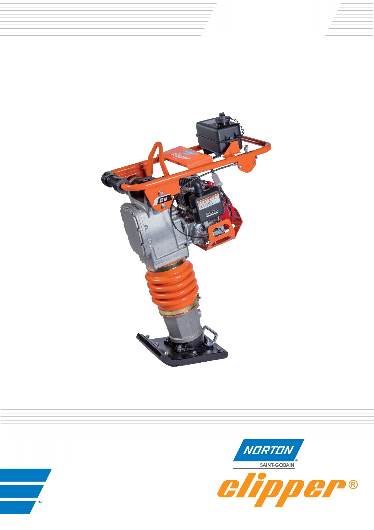
CR16
Translation of the original Instructions
Rammer
OPERATING INSTRUCTIONS
Page 2

VERS. 01.09.2019 CR16 _MAN_EN
Declaration of conformity
The undersigned manufacturer: SAINT - GOBAIN ABRASIVES S.A.
190, BD. J. F. KENNEDY
L-4930 BASCHARAGE
Declares that this product: Norton clipper CR16 Code: 70184608012
Is in conformity with the following Directives:
"MACHINES" 2006/42/CE
"NOISE" 2000/14/CE
And European standard :
• EN 500-1 Mobile road construction machinery. Safety - Part 1: Common requirements
• En 500-4 Mobile road construction machinery - Safety - Part 4: Specific requirements for
compaction machines
Valid for machines as of serial number : 450xxxxxxx
Storage site for the technical documents :
Saint-Gobain Abrasives 190, Bd. J. F. Kennedy 4930 BASCHARAGE, LUXEMBOURG
This declaration of conformity loses its validity when the product is converted or modified without agreement.
Bascharage, Luxembourg, le 01.09.2019 :
François Chianese, executive officer.
2
Page 3

VERS. 01.09.2019 CR16 _MAN_EN
Norton Clipper CR16
OPERATING INSTRUCTIONS
TABLE OF CONTENTS
1 BASIC SAFETY INSTRUCTIONS
1.1 Symbols
1.2 Machine plate
1.3 Safety instructions for particular operating phases
2 MACHINE DESCRIPTION
2.1 Short description
2.2 Purpose of use
2.3 Layout
2.4 Technical Data
2.5 Statement regarding the vibration emission
2.6 Statement regarding noise emission
3 ASSEMBLY AND COMMISSIONING
4 TRANSPORT AND STORING
4.1 Securing for transport
4.2 Transport procedure
4.3 Long period of inactivity
5 OPERATING THE MACHINE
5.1 Site of work
5.2 Preparing the site
5.3 Floating and finishing operation
6 MAINTENANCE AND SERVICING
6.1 Maintenance of the machine
7 FAULTS: CAUSES AND CURES
7.1 Fault-finding procedures
7.2 Trouble-shooting guide
7.3 Spare parts
1-BASIC SAFETY INSTRUCTIONS
The Noron Clipper CR16 is exclusively designed for compaction mainly on construction sites.
3
Page 4
VERS. 01.09.2019 CR16 _MAN_EN
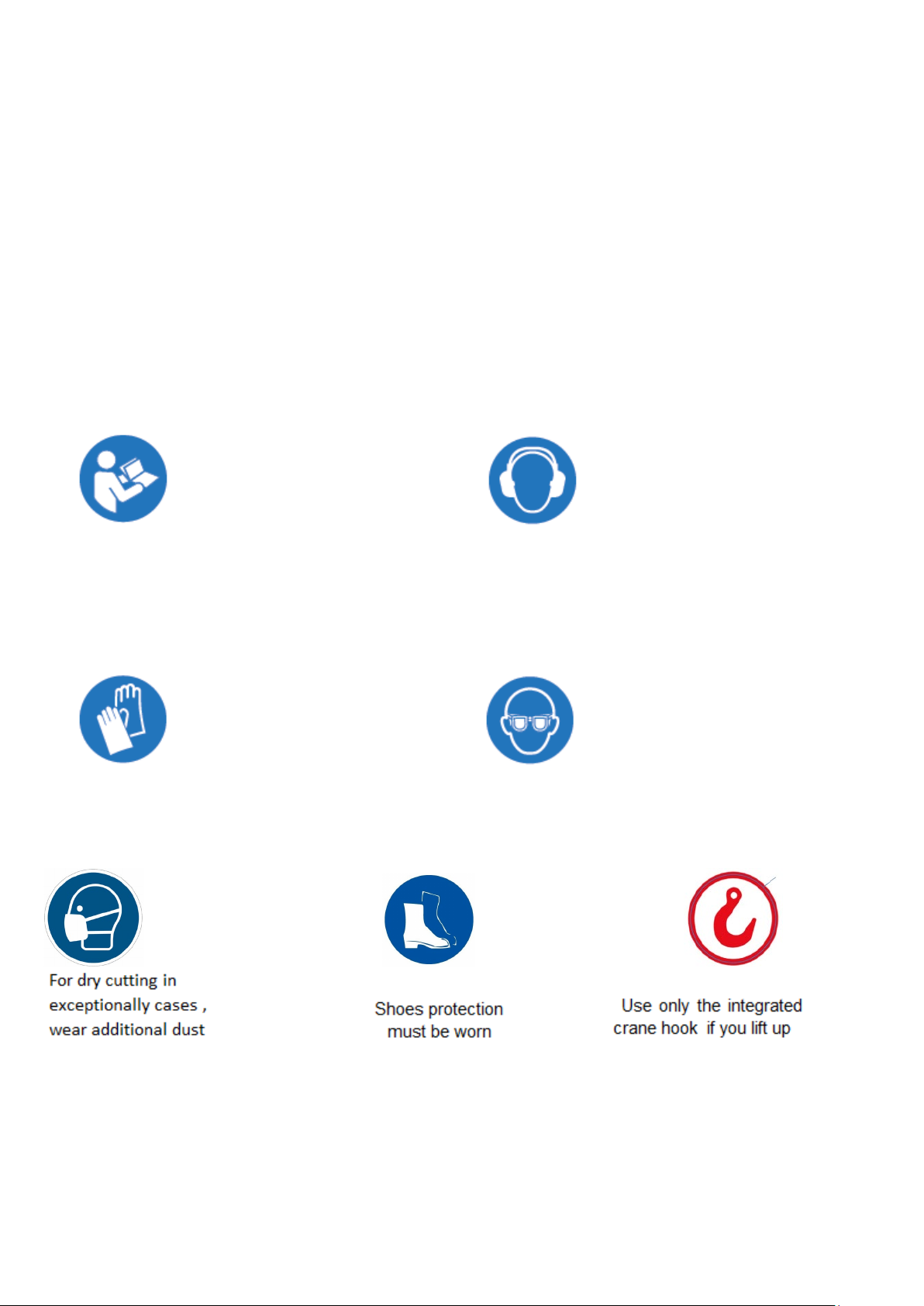
Read operator's instructions
Ear protection must be worn
Hand protection must be worn
Eye protection shall be worn
Uses other than the manufacturer's instructions shall be considered as contravening the regulations.
The manufacturer shall not be held responsible for any resulting damage. Any risk shall be borne
entirely by the user. Observing the operating instructions and compliance with inspection and
servicing requirements shall also be considered as included under use in accordance with the
regulations.
1.1 Symbols
Important warnings and pieces of advice are indicated on the machine using symbols. The following
symbols are used on the machine:
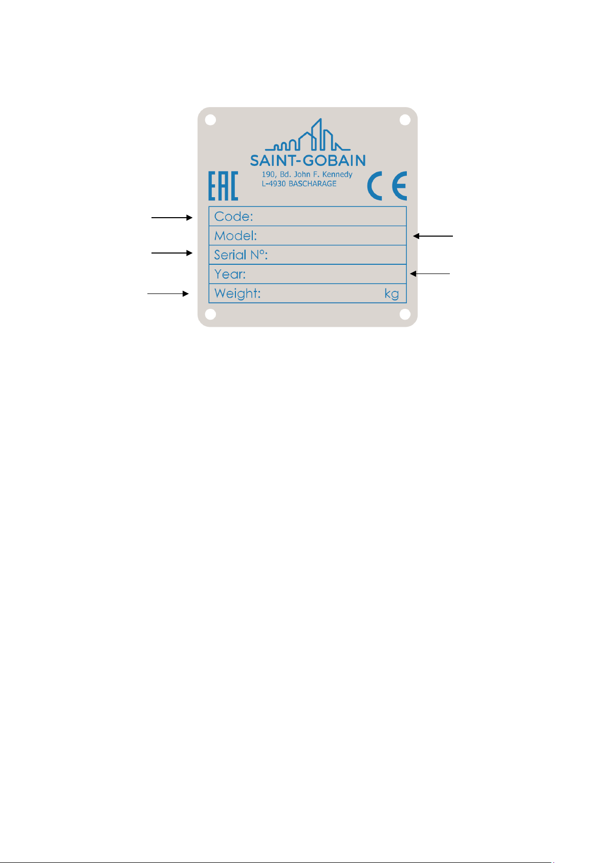
1.2 Machine plate
Important data can be found on the following plate located on the machine:
4
Page 5
VERS. 01.09.2019 CR16 _MAN_EN
Machine model
Machine code
Machine Weight
Year of production
Serial number
1.3 Safety instructions for particular operating phases
Before starting the work
• Before commencing work, make yourself familiar with the working environment at the place
of use. The working environment includes: obstacles in the area of work and manoeuvre, the
firmness of the floor, necessary protection at the site relating to public thoroughfares and the
availability of help in the event of accidents..
• This machine must only be used for its intended purpose, and must be operated only by the
well-trained personnel.
• Know how to stop the engine quickly, and understand the operation of all controls BEFORE
attempting to operate the machine.
• The machine must be operated on ground where stability is guaranteed. When working near
the rim of excavated trenches, be alert to potential caving edges, falling rocks, and slides.
• The exhaust gas contains poisonous and hazardous CARBON MONOXIDE. Exposure can
cause loss of consciousness and may lead to death. Use this machine in a well ventilated
area. Never operate the machine in room, warehouse, tunnel, mine, or in a deep trenches
where the exhaust may not be properly vented to the atmosphere.
• The exhaust pipe and muffler is subject to extremely high temperature during and after
operation. Do not touch it unless these are completely cooled off. Let the engine cool before
storing the machine indoors.
• Do not attempt to run the machine with any of the covers, labels, and/or any other
components removed from the machine. Unauthorized alteration or modification of the
engine or the machine is prohibited, as it will affect the machine's performance and may
lead to danger in operation
.
5
Page 6
VERS. 01.09.2019 CR16 _MAN_EN
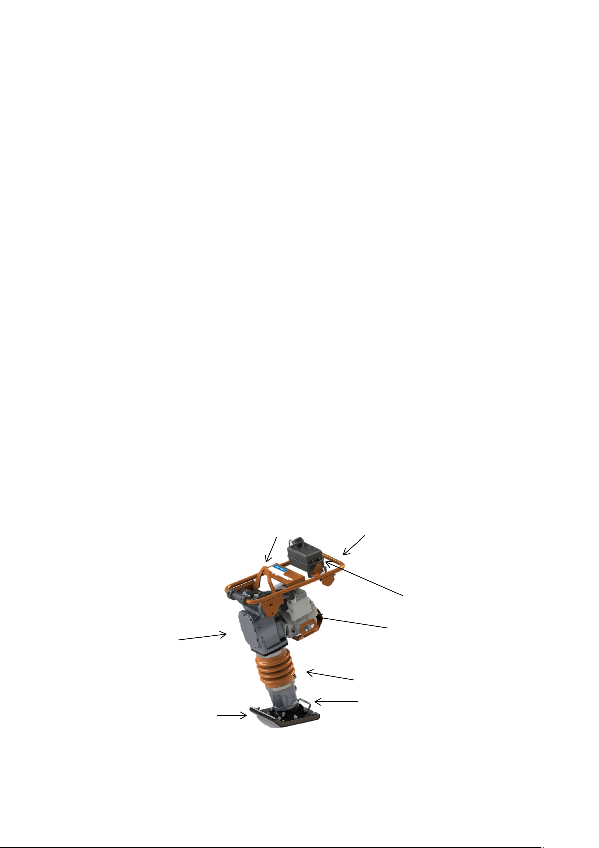
6 1 3 5 4 2 7
8
2-MACHINE DESCRIPTION
Any modification, which could lead to a change in the original characteristics of the machine, may
be done only by Saint-Gobain Abrasives who shall confirm that the machine is still in conformity with
the safety regulations.
2.1 Short description
The rammer CR16 is suitable for repairing asphalted surfaces, for small compacting jobs and for
preparing green areas
As with all other NORTON products, the operator will immediately appreciate the attention given to
detail and quality of materials used in construction. The machine and its component parts are
assembled to high standards assuring long life and minimum maintenance.
2.2 Purpose of use
The percussion and the vibration required for compaction are produced by the vibrator located on
the compacting plate.
The engine starts the vibrator and the torque is transmitted by the centrifugal clutch and the belt.
To allow the minimum of the driving motor, the centrifugal clutch, at low engine speeds, interrupts
the flow of power towards the exciter. The compactor must always be used with the gas handle in
the "OPERATIVE" position.
The motor support and the compaction plates are connected by 4 shock absorbers, which are
mounted to prevent the vibrations reaching the operator.
Use the machine only for the purpose for which it was designed.
2.3 Layout
6
Page 7

VERS. 01.09.2019 CR16 _MAN_EN
Handlebar (1)
Jig welded steel construction is connected by 4 shock mount on the frame of the machine to reduce
the vibrations reach the operator
Lifting eye (2)
To lift the machine easily and safely, a lifting eye is located over the engine. This allows a balanced
lifting of the machine.
Petrol tank (3)
The 2 liter fuel tank is located on the handlebar for easy filling.
Thermal Engine (4)
The machine is equipped with a Honda engine GXR120 with 2.6 kW.
Transfert box (5)
oil bath transfer box which transmits the vibration to the soleplate via the piston / cylinder
Piston/Cylinder (6)
Transmits the vibration to the soleplate
SolePlate (7)
The sole plates have rounded edges and raised to avoid marking the surface
7
Page 8

VERS. 01.09.2019 CR16 _MAN_EN
Model
Norton Clipper CR16
Operating weight
70 kg
Overall Lenth
720mm
Overall Heigth
1045mm
Overall Wigth
415mm
Centrifugal force
16 kN
Impact Number per minutes
640-680
Stroke
50-75mm
Air-cooled single-cylinder 4 stroke
Honda GXR120
Engine power
kW 2,6 (HP 3,5)
rpm
3550-3600
Displacement
121 cm3
Fuel
Petrol
Fuel consumption
1,5
Fuel tank capacity
3,1 ltrs
2.4 Technical DATA
Ramming soleplate Width x
Length
Engine
280x330mm
2.4 VIBRATION MEASUREMENTS
Products are tested for hand/arm vibration level in accordance with annex D prEN500-4:2001
The hand/harm vibration level is 8 m/s
The rammer has been tested on a “macadam” surface, produced with not cleaned stone crusher
grit, with 16 mm medium diameter (with components which have diameter that goes from 10 to 20
mm).
2.5 SOUND MEASUREMENTS
The product has been produced in accordance with the standard 2000/14/CE, procedure I annex VI.
Measured sound power level 105 [dB(A)] and guaranteed sound power level 108 [dB(A)] on a
significant equipment.
3-ASSEMBLY AND COMMISSIONING
Starting the machine
8
2
Page 9
VERS. 01.09.2019 CR16 _MAN_EN
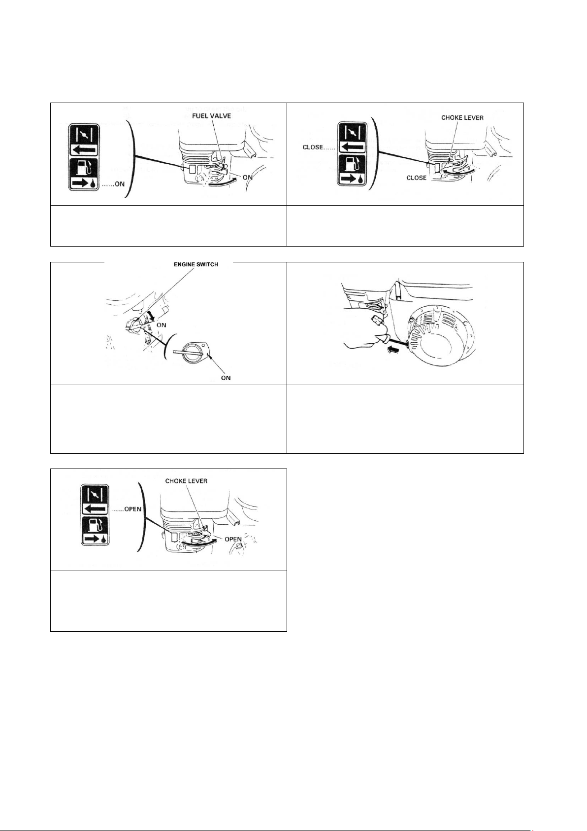
Turn the fuel valve to the ON position. Fully press
Move the choke lever to the CLOSED position.
Move the throttle control lever slightly to the left.
Pull the starter grip lightly until you feel resistance,
CAUTION: Do not allow the starter grip to snap
As the engine warms up, gradually move the
Position the throttle control lever for the
the dead-man handle against the main handle.
Put the engine switch on ON.
NOTE: do not use the choke if the engine is warm
or the air temperature is high.
then pull briskly.
back against the engine. Return it gently to prevent
damage to the starter.
choke lever to the OPEN position.
maximum engine speed.
To stop the engine, release the dead-man handle, move the throttle control lever fully to the right,
then turn the engine switch to the OFF position. Turn the fuel valve to the OFF position.
CAUTION: when the machine is switched off, the tools will continue turning slowly to complete stop.
Be therefore very careful to avoid injuries.
9
Page 10

VERS. 01.09.2019 CR16 _MAN_EN
4-Transport and storing
4.1 Securing for transport
Conform yourself to work regulations, in order to transport the machine safely. To help you transport
the machine, you can remove the transport tube from under the handle and located in the front hole
of the machine.
4.2 Transport procedure
Conform yourself to work regulations, in order to transport the machine safely. To help you transport
the machine, you can remove the transport tube from under the handle and located in the front hole
of the machine.
4.3 Long period of inactivity
If the machine is not going to be used for a long period, completely clean the machine and
disassemble the tools. The storage site must be clean, dry and at a constant temperature.
5- OPERATING THE MACHINE
5.1 Site of work
• Remove from the site anything, which might hinder the working procedure!
• Make sure the site is sufficiently well lit!
• Make sure you have a continual adequate view of the working area so you can intervene in the
working process at any time!
• Keep other staff out of the area, so you can work securely.
5.2 Preparing the site
Ad equation to compaction, it will be necessary to identify the characteristics of soils and material, to
study their ability
6- MAINTENANCE AND SERVICE
6.1 Maintenance of the machine
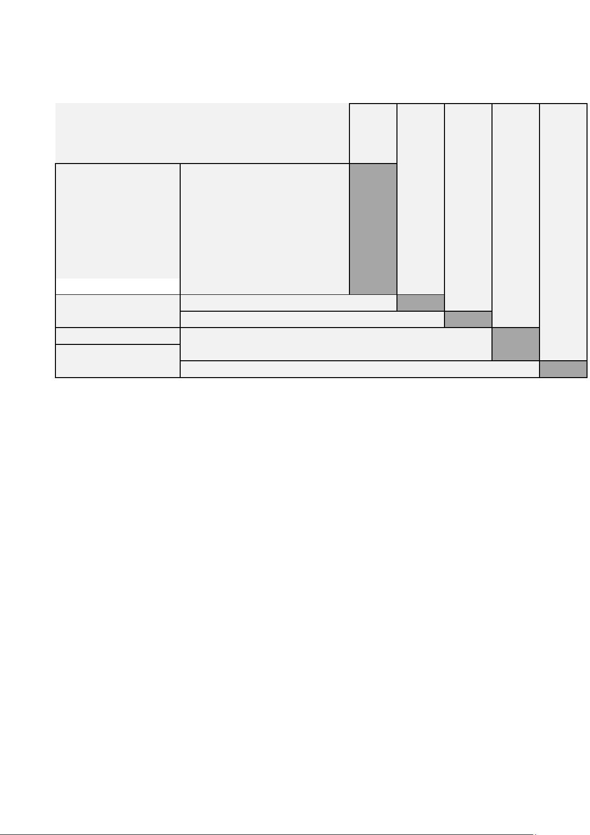
To ensure a long-term quality from the use of the Clipper compactors CR16, please follow the
maintenance plan below:
10
Page 11
VERS. 01.09.2019 CR16 _MAN_EN
After
20h00
Monthly
After
100h00
After
200h00
Check filter, clean or replace if
necessary
Check filter oil level (only oil bath
models)
Check fuel tank and fuel cap lid.
If necessary replace.
Engine
Check oil level, refill if necessary
Engine
Check engine RPM
Transfert Box
Check exciter lid
First oil change
Clean spark plug
Fuel Tank
Check fuel filter, replace if necessary
Oil change
Oil change
Air filter
Oil filter
Fuel tank
Engine
Engine and transfert
box
Daily
11
Page 12
VERS. 01.09.2019 CR16 _MAN_EN
Engine Switch is set to
OFF
Main jet of the carburetor
Take out the main jet from
being clogged with dirt.
carburetor, and clean the
the jet with compressed
air.
Tightly fit the plug cap
7-FAULT: CAUSES AND CURES
7.1 Fault –finding procedures
Should any fault occur during the use of the machine, turn it off. Any works dealing with the engine
of the machine can only be carried out by a qualified technician.
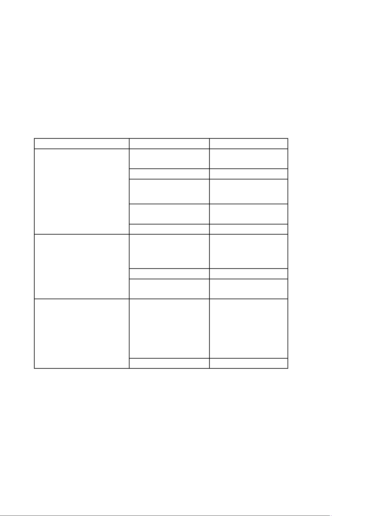
7.2 Troubles-shooting guide
TROUBLE POSSIBLE CAUSE REMEDY
Insufficient fuel.
Fuel Cock is closed. Open the fuel cock.
Refuel with Automotive
gasoline.
Engine won't start.
Engine stops suddenly,
Engine runs, but the machine
Set the switch to ON.
position.
Spark Plug contaminated
or damaged.
Improper spark plug gap Correct the gap.
Air Filter Element dirty. Clean the element.
Spark Plug cap is loose.
Lack of engine power. See above.
Clutch slipping. Dismantle the clutch
shoe if necessary.
Crank/Gear unit damaged. Contact dealer.
Replace the spark plug.
to the plug.
assembly, and clean the
shoe and drum with pro-
per solvent. Replace the
12
Page 13

VERS. 01.09.2019 CR16 _MAN_EN
7.3 Spare parts
In order to consult the spare parts lists, we invite you to visit the after-sales website of Norton
Clipper by using the following address:
https://spareparts.nortonabrasives.com
For a quick access, you can also use the QR Code shown below using your mobile phone:
This electronic catalogue provides exploded views and spare parts lists for different machines
designed by Norton Clipper so you can find references you need.
When ordering spare parts, please mention:
• The serial number.
• The code of the part.
• The exact denomination.
• The number of parts required.
• The delivery address.
• Please indicate clearly the means of transportation required such as "express" or "by air".
Without specific instructions, we will forward the parts through the means which seem
appropriate to us --- but which is not always the quickest way.
Clear instructions will avoid problems and faulty deliveries.
If not sure, please send us the defective part. In the case of a warranty claim, the part must always
be returned for evaluation. Spare parts for the motor can be ordered with the manufacturer of the
motor or with their dealer, which is often quicker and cheaper.
This machine has been manufactured by
190, Bd. J.F. Kennedy
L- 4930 BASCHARAGE
Grand-Duché de Luxembourg.
Tel.: 00352-50401-1
http://www.construction.norton.eu
e-mail: sales.nlx@saint-gobain.com
Saint-Gobain Abrasives S.A.
13
Page 14

VERS. 01.09.2019 CR16 _MAN_EN
SAINT-GOBAIN ABRASIVES
TEL: +36 1 371 22 50
SAINT-GOBAIN ABRASIVI S.P.A
SAINT-GOBAIN GLASS
I SOK. NO:21
Guarantee can be claimed and technical support obtained from your local distributor where
machines, spare parts and consumables can be ordered as well:
INDUSTRIEWEG 21
9420 ERPE-MERE
BELGIUM
TEL:
+32(0) 2 267 21 00
SAINT-GOBAIN ABRASIVES, S.R.O.
POČERNICKÁ 272/96, MALEŠICE
108 00 PRAHA 10
CZECH REPUBLIC
TEL: +420 255 719 326
FAX: +420 255 719 321
SAINT-GOBAIN ABRASIVES A/S
DYBENDALSVÆNGET 2,
DK-2630 TAASTRUP
DENMARK
TEL:
+45 4675 5244
PO BOX 643706
FORTUNE TOWER OFFICE 2106
JLT BLOCK C
(NEXT TO METRO STATION)
JUMEIRA LAKE TOWER, DUBAI
UNITED ARAB EMIRATES
TEL: +971 4 431 5154
FAX: +971 4 431 5434
SAINT-GOBAIN ABRASIFS
RUE DE L’AMBASSADEUR - B.P.8
78 702 CONFLANS CEDEX
FRANCE
TEL: +33 (0)1 34 90 40 00
FAX: +33 (0)1 39 19 89 56
SAINT-GOBAIN ABRASIVES GMBH
BIRKENSTRASSE 45-49
D-50389 WESSELING
GERMANY
TEL: +49 (0) 2236 703-1
+49 (0) 2236 8996-0
+49 (0) 2236 8911-0
FAX: +49 (0) 2236 703-367
+49 (0) 2236 8996-10
+49 (0) 2236 8911-30
FÜR DEN FACHHANDEL
ÖSTERREICH
TEL: +43 (00) 662 430 076
SAINT-GOBAIN ABRASIVES KFT.
1225 BUDAPEST
BÁNYALÉG U. 60/B.
HUNGARY
VIA PER CESANO BOSCONE 4
I-20094 CORSICO MILANO
ITALY
TEL: +39 02 44 851
FAX: +39 02 44 78 266
SAINT-GOBAIN ABRASIVES S.A.
190 RUE J.F. KENNEDY
L-4930 BASCHARAGE
GRAND DUCHE DE LUXEMBOURG
TEL: +352 50 401 1
FAX: +331 83 717 792
NO. VERT (FRANCE): 0800 906 903
SAINT-GOBAIN ABRASIFS, S.A.
2 ALLÉE DES FIGUIERS
AIN SEBAÂ - CASABLANCA
MOROCCO
TEL: +212 5 22 66 57 31
FAX: +212 5 22 35 09 65
SAINT-GOBAIN ABRASIVES BV
GROENLOSEWEG 28
7151 HW EIBERGEN
P.O. BOX 10
7150 AA EIBERGEN
THE NETHERLANDS
TEL: +31 545 466466
FAX: +31 545 474605
SAINT-GOBAIN ABRASIVES AS
POSTBOKS 11, ALNABRU,
0614 OSLO
BROBEKKVEIEN 84,
0582 OSLO
NORWAY
TEL: +47 63 87 06 00
FAX: +47 63 87 06 01
SAINT-GOBAIN HPM POLSKA SP. Z O.O.
UL. NORTON 1, 62-600 KOŁO
62-600 KOŁO
POLAND
TEL: +48 63 26 17 100
FAX: +48 63 27 20 401
SAINT-GOBAIN ABRASIVOS, L. DA
ZONA INDUSTRIAL DA MAIA
I-SECTOR VIII, NO. 122
APARTADO 6050
4476 - 908 MAIA
PORTUGAL
TEL: +351 229 437 940
BUSINESS UNIT ABRASIVI
PUNCT DE LUCRU: LOC.VETIS,JUD.
SATU MARE 447355
STR. CAREIULUI 11
PARC INDUSTRIAL RENOVATIO
ROMANIA
TEL: +40 261 839 709
FAX: +40 261 839 710
SG HPM RUS
58, F. ENGELS STR.
STROENIE 2
105082 MOSCOW
RUSSIA
TEL: +74 955 408 355
FAX: +74 959 373 224
SAINT-GOBAIN
ABRASIVES (PTY) LTD
2 MONTEER ROAD
ISANDO 1600
P.O. BOX 67
SOUTH AFRICA
TEL: +27 11 961 2000
FAX: +27 11 961 2184/5
SAINT-GOBAIN ABRASIVOS, S.A.
CTRA. DE GUIPÚZCOA, KM. 7,5
E-31195 BERRIOPLANO (NAVARRA)
SPAIN
TEL: +34 948 306 000
FAX: +34 948 306 042
SAINT GOBAIN ABRASIVES AB
GÅRDSFOGDEVÄGEN 18A
168 66 BROMMA • SVERIGE
SWEDEN
TEL: +46 8 580 881 00
FAX: +46 8 580 881 30
SAINT-GOBAIN INOVATIF MALZEMELER
VE ASINDIRICI SAN. TIC. AS.
ALTAYÇEŞME MAH. ÇAML
ESAS OFISPARK KAT:9 34843
MALTEPE, İSTANBUL • TURKEY
TEL:
0090-216-217 12 50
FAX: 0090-216-442 40 74
SAINT-GOBAIN ABRASIVES LTD.
DOXEY RD
14
Page 15

VERS. 01.09.2019 CR16 _MAN_EN
FAX: +36 1 371 22 55
FAX: +351 229 437 949
STAFFORD
ST16 1EA
UNITED KINGDOM
TEL: +44 1785 222 000
FAX: +44 1785 213 487
15
 Loading...