

Page 1

Contents
1 Introduction ........................................................................................................................ 4
1-1 SmartCraft data available from different engines .......................................................................4
1-2 What comes with your gateway .........................................................................................................5
2 Installation .......................................................................................................................... 6
2-1 Connecting the gateway to the SmartCraft system ...................................................................6
2-2 Connecting the gateway to the Navman instrument ...............................................................7
2-3 Installation ...................................................................................................................................................7
3 Operation with a Navman FISH 4380 ............................................................................... 8
3-1 Setting up the FISH 4380 for SmartCraft .........................................................................................9
3-2 SmartCraft Engine data displays .....................................................................................................10
3-3 Troll control .............................................................................................................................................. 11
3-4 Trim indicator ..........................................................................................................................................12
3-5 Engine fault alarms ............................................................................................................................... 12
3-6 Engine fault lists .....................................................................................................................................13
3-7 SmartCraft setup data .........................................................................................................................14
3-8 SmartCraft calibration ......................................................................................................................... 16
4 Operation with a Navman TRACKFISH 6600 ..................................................................... 18
4-1 Setting up the TRACKFISH 6600 for SmartCraft ........................................................................19
4-2 SmartCraft engine data displays ..................................................................................................... 19
4-3 Troll control .............................................................................................................................................. 21
4-4 Trim Indicator ..........................................................................................................................................21
4-5 Engine fault alarms ............................................................................................................................... 22
4-6 Engine fault lists .....................................................................................................................................22
4-7 SmartCraft setup data and calibrations ....................................................................................... 23
5 Operation with a Navman FISH 4600 .............................................................................27
5-1 Setting up the FISH 4600 for SmartCraft ...................................................................................... 28
5-2 SmartCraft engine data displays ..................................................................................................... 28
5-3 Troll control .............................................................................................................................................. 30
5-4 Trim Indicator ..........................................................................................................................................30
5-5 Engine fault alarms ............................................................................................................................... 31
5-6 Engine fault lists .....................................................................................................................................31
5-7 SmartCraft setup data and calibrations ....................................................................................... 32
Appendix A Specifications .................................................................................................36
Appendix B Troubleshooting ............................................................................................. 36
Appendix C SmartCraft accessories .................................................................................. 37
Appendix D How to contact us .......................................................................................... 38
SmartCraft gateways Installation and Operation Manual NAVMAN
3
Page 2

1 Introduction
The Navman SmartCraftTM gateway connects one
or two SmartCraft capable Mercury petrol/gasoline
engines to a SmartCraft capable Navman instrument, such as the FISH 4380, FISH 4600 or TRACKFISH 6600. The single gateway is for single engines,
the dual gateway is for twin engines.
Adding the gateway extends the functions of the
Navman instrument, allowing the instrument to:
Display engine data, such as speed, RPM,
pressures, tank levels.
Control troll speed and display trim.
Sound an alarm if it detects an abnormal
engine condition.
This manual describes:
How to install a Navman SmartCraft gateway.
How to use the SmartCraft functions of a Navman SmartCraft capable instrument. Refer to
the separate Navman instrument Installation
and Operation Manual for information on how
to install and use the instrument.
The engine data available in a system depends
on the ty pe of en gine us ed (se e section 1-
1). The gatewa y rep laces any fuel flow sensors that might be plugged into the Navman
instrument .
It is vital to read this document and the associated
SmartCraft and Navman installation and operation
manuals before installing or using the system.
1-1 SmartCraft data available from different engines
The SmartCraft engine data available in a system depends on the type of engine. SmartCraft is a digital engine network
provided on some later model (2002 +) Mercury and Mariner Engines, both in-board and out-board.
Engine type
Engine data available
Steering Angle
Fuel level
Oil temperature
Oil Pressure
Engine Trim
Water Pressure
Engine temperature
Fuel Flow
Fuel Level
Engine voltage
Pitot water (boat) speed
RPM
4
V-6 EFI
Optimax 75- 115
Optimax 135-250
Optimax 225 DTS
Verado
Mercruiser 4.3 L
Mercruiser 5.0 L
Mercruiser 5.7 L
4 Stroke 30 - 60
NAVMAN
SmartCraft gateways Installation and Operation Manual
Mercruiser 6.2 L
Mercruiser 8.1 L
496 HO
Page 3

1-1-1 Tanks and sensors
Engines can have optional level sensors fitted:
A two-stroke engine can have one sensor
fitted to its oil tank, and one additional sensor
fitted to a fuel, oil, water or waste tank.
A four stroke engine can have one or two
sensors fitted to its fuel, water or waste tanks.
If level sensors are fitted: the tank levels can be
displayed; there are alarms for low tank levels; the
tanks must be set up and calibrated (see following
sections:
1-2 What comes with your gateway ?
Built-in cable to the Navman
instrument, 1 m (3.3 ft) long
Holes for mounting screws
Built-in cable to the SmartCraft system, 300
mm (1 ft.) long
Gateway LEDS:
NAV (orange): Flashes fast when the gateway is
exchanging data with the Navman instrument and
the engine key is on.
PWR (green): On when power and the engine
key are on.
CAN (red): Flashes fast when the gateway is exchanging data with the SmartCraft engine(s) and
• Two mounting screws (8 gauge x 5/8 inch,
Pan pozi, self tapping, stainless steel);
• warranty card;
• this manual.
FISH 4380 : Section 3-8-1
TRACKFISH 6600 : Section 4-7-1
FISH 4600 : Section 5-7-1
SmartCraft Gateway
Also supplied:
Optional extras for SmartCraft
AA002237
SmartCraft gateways Installation and Operation Manual NAVMAN
Power/fuel splitter cable
A power/fuel splitter cable (‘Y’ cable) is required
for Navman instruments that do not have a
separate fuel sensor connector (such as the FISH
4380, see section 2-2). This cable is included in
hardware packages AA005022 and AA005023
and is also available separately from your Navman dealer.
Also see Appendix-C
5
Page 4

2 Installation
A system in a boat comprises:
a. One or two SmartCraft capable petrol/gaso-
line engines; the data available depends
on engine type and the sensors fitted (see
section 1-1).
b. A single or dual engine gateway.
c. A SmartCraft capable Navman instrument,
such as the FISH 4380, FISH 4600 or TRACKFISH 6600.
d. Other optional Navman instruments and
SmartCraft displays. See Appendix-C
Warning: Correct installation is critical to
the performance of the unit. Before starting
installation, it is vital to read this manual and the
documentation that comes with the other parts.
Then plan the installation and select where the
equipment and cables will be located.
Warning: Ensure that any holes that you cut
will not weaken the boat’s structure. If in doubt,
consult a qualified boat builder.
2-1 Connecting the gateway to the SmartCraft system
Using a Navman cable adaptor: Use a Navman cable adaptor in a single engine system which does not
have optional SmartCraft displays. However, a SmartCraft junction box should be used if future expansion
of the SmartCraft system is planned.
SmartCraft harness 879982T-x
(x = length in feet)
Petrol
engine
Using a SmartCraft junction box: Connect the gateway to a SmartCraft Junction box in a twin engine
system or in any system with optional SmartCraft displays.
SmartCraft harness 879981T-x
Petrol
engine
(x = length in feet)
SmartCraft cable adaptor 892452A01
Single engine gateway
Fit optional SmartCraft displays, or
fit Mercury weather cap 859318T-2
Petrol
engine
There must be two SmartCraft Terminators in any SmartCraft Installation. The Mercury harness 84-879982T-x
has two terminators built-in; the Mercury harness 84-879981T-x has one terminator built-in.Terminators
must be positioned at the furthermost ends of the SmartCraft network.
Refer to a Mercury SmartCraft manual, such as Wiring for SmartCraft Gauges (Mercury part 90-879939), for
details of installation configurations and requirements, alternative termination methods and additional
SmartCraft components such as harnesses, junction boxes and terminators. Also see Appendix C
To use the SmartCraft functions, install the SmartCraft gateway (see section 2), then go to the System setup
menu on the Navman Instrument and turn SmartCraft to On (See Setup > System menu).
6
Optional
SmartCraft junction box
878492B-4
NAVMAN
Single or dual engine gateway
SmartCraft gateways Installation and Operation Manual
Page 5

2-2 Connecting the gateway to the Navman instrument
For a Navman instrument without a white fuel
sensor connector (such as a FISH 4380):
Power/fuel splitter
cable (‘Y’ cable)
Plug gateway into
white connector
FISH 4380
Other wiring,
refer to the
instrument’s
manual
For any Navman instrument, using a NavBus junction box to connect to power/data cable (black
power connector):
Power/data
cable
Other wiring,
refer to the
instrument’s
manual
NavBus
junction box
For a Navman instrument with a white fuel sensor connector (such as a FISH 4600 or TRACKFISH
6600):
Plug gateway into
white connector
FISH 4600,
TRACKFISH
6600
Other wiring,
refer to the
instrument’s
manual
The wires from the gateway to the Navm an
instrument cab le can be con nect ed to the
instrument’s power/data cable. This option is not
normally necessary. For more information, refer to
your Navman dealer.
Cut white connector off gateway cable. Connect
five gateway cable wires (red, black, blue, orange,
brown) to the same colour wires in the power/
data cable. An optional Navman NavBus junction
box simplifies wiring.
2-3 Installation
1 Plan the installation: select where the equip-
ment and wiring will be installed. Ensure
that gateway can be located on a panel near
the Navman instrument, where it will not
interfere with the operation of the boat. (eg:
cables are long enough for the installation
planned)
2 Screw the gateway to the panel using the
screws provided.
3 Connect the gateway (see sections 2-1 and
2-2). Secure the cables at regular intervals.
4 Power up, set up and test the system. Check
the gateway LEDs:
NAV (orange): Flashes fast when gateway is
exchanging data with the Navman instrument and the engine key is on.
PWR (green): On when power and the engine
key are on.
CAN (red): Flashes fast when gateway is ex-
changing data with the SmartCraft engine(s)
and the engine key is on.
Important:
1 Do not connect any Navman fuel sensors to
the Navman instrument.
2 It is not necessary to wire any Navman instru-
ment for auto power on.
3 The Navman SmartCraft capable instrument
sends SmartCraft data to other
Navman instruments connected by NavBus.
To connect other instruments by NavBus, see
the instrument’s installation and operation
manual. Turn NavBus on in all Navman instruments connected by NavBus; for example, for
a Fish 4380, in the Comms setup menu, turn
NavBus to On.
4 A gateway does not provide data for system
link gauges.
5 To use speed troll control, the Navman instru-
ment must have a Navman paddlewheel
speed sensor connected.
SmartCraft gateways Installation and Operation Manual NAVMAN
7
Page 6

3 Operation with a Navman FISH 4380
Before a SmartCraft gateway is connected, the FISH 4380 functions normally, with no SmartCraft functions.
When a SmartCraft gateway is connected and SmartCraft is turned On (see section 3-1), SmartCraft
functions become available and some standard functions change.
SmartCraft features
Data displays
Engine performance and tank level displays .............................................................................................See section 3-2
Troll control
Automatically maintains a set engine idle RPM or idle boat speed ................................................See section 3-3
Trim indicator
Displays the trim angle when engine trim is adjusted ..........................................................................See section 3-4
Alarms
SmartCraft engine fault alarms ........................................................................................................................See section 3-5
Engine fault list, a list of active SmartCraft engine fault alarms .........................................................See section 3-6
Engine fault history, a list of past SmartCraft engine fault alarms ....................................................See section 3-6
Tank low level alarms ...........................................................................................................................................See section 3-2
Setup data and calibrations
SmartCraft setup data .......................................................................................................................See sections 3-1 and 3-7
SmartCraft calibrations, Tanks, Trim and Steering angle. ...................................................See section 3-8
The SmartCraft data available depends on the engine type and the sensors fitted (see section 1-1). To disable
the SmartCraft functions, turn SmartCraft to Off (see section 3-1); the instrument will now use any
Navman fuel sensors which are connected.
To use the SmartCraft functions and not the sonar functions, turn Sonar to Off (see section 3-1).
Changes to standard functions with SmartCraft
If no fuel tanks have an optional level sensor fitted (see section 1-1-1), then the Smartcraft fuel flow is
If each fuel tank has an optional level sensor fitted (see section 1-1-1), then these tank levels are used
For more information, see the FISH 4380 Installation and Operation manual.
key: When using troll control, pressing can display the troll window. Press a
second time to display the normal menu of options.
Fuel display: The fuel display functions normally, with fuel and speed data coming from the SmartCraft system rather than from separate sensors connected to the FISH 4380.
Fuel setup options:
used to calculate fuel remaining. The fuel setup data is the same as the standard FISH 4380. You must
tell the FISH 4380 when you add or remove fuel (see the FISH 4380 Installation and Operation manual).
to calculate fuel remaining. In the Fuel display, Used changes to Trip used, and the only fuel
setup option is Clear trip used. Trip used measures the volume of fuel used until it is reset
to zero by selecting Clear trip used in the fuel setup menu. You do not tell the FISH 4380 when
you add or remove fuel.
Engine hours: Engine hours on the Log display come from the SmartCraft system.
It can not be reset.
Simulate mode: Data from the SmartCraft engine(s) and sensors is simulated in Simulate mode. The
SmartCraft features simulated will probably differ from the features available in your system.
8
NAVMAN
SmartCraft gateways Installation and Operation Manual
Page 7

3-1 Setting up the FISH 4380 for Smartcraft
3-1 Setting up the FISH 4380 for Smartcraft
These features can be used only when the optional
single or twin engine SmartCraft Gateway has been
installed.
Press twice to display the Setup menu, then
select SmartCraft.
Press to select On or Off
Note: NavBus will be turned on when SmartCraft
is turned on.
Sonar
Select:
Off: The sonar transducer and the sonar
functions are disabled. Choose Off to use
the instrument’s SmartCraft functions only,
On: Normal sonar operation.
SmartCraft
Select:
Off: The SmartCraft functions and NavBus
are disabled. The instrument will now use any
Navman fuel sensors which are connected.
On: Normal SmartCraft operation.
SmartCraft gateways Installation and Operation Manual NAVMAN
9
Page 8

3-2 SmartCraft engine data displays
To display the SmartCraft data, press and
select SmartCraft, then press , or
or to select one of the four SmartCraft displays,
shown below.
For the Small, Medium and Large gauges:
The factory default has gauges appropriate
to the type of engine. To change what gauges
are displayed, see section 3-7: Gauge setup.
If the boat has twin engines, the red needle
Small: Six small ‘analogue’ gauges: Medium: Two medium & two small ‘analogue’
Header
data
or number shows port data, green shows
starboard data.
The gauges can be set up to be analogue
(dial) or digital (number) (see section 3-7:
Gauge type and Speed range).
Each display has three items of header data. To
select what data is displayed, see section 3-7:
Header setup.
gauges
Large: Two large ‘analogue’ gauges
10
Tanks: Tank levels (see next page)
NAVMAN
SmartCraft gateways Installation and Operation Manual
Page 9

Tank level display
The tank level display shows the levels from the optional level sensors in one or two tanks per engine
(see section 1-1-1).
Note:
Each tank must be set up and calibrated (see
section 3-8-1).
3-3 Troll control
Troll control allows adjustment of the engine’s idle
speed from the Navman instrument. Troll control
automatically controls the engine idle speed to
maintain a set engine RPM or boat speed.
To use troll control, set Troll window to On
idle or Always and set Troll mode to Speed
or RPM (see section 3-7). To use speed troll control,
set Speed type to Paddle (see section 3-7).
To prohibit troll control, set Troll window to Never
(see section 3-7).
Engaging troll control
1 Set the throttle(s) to idle and the engine(s) in
gear. From a main display, press to
display the Troll control window (see right).
2 Press or to set the desired RPM or boat
speed (see notes 1 and 2).
3 Press to engage troll control. The FISH
4380 automatically controls RPM or speed. Or,
press to leave troll control disengaged.
Changing RPM or speed while troll
control engaged
1 From a main display, press to display
the troll window.
2 Press or to change the desired RPM or
boat speed (see notes 1 and 2).
3 Press .
Disengaging troll control
Either move the throttle from idle, or:
1 From a main display, press to display
the troll window.
2 Press to disengage troll control.
Or, press to leave troll control engaged.
Note:
An alarm can be set to sound if the level in a
tank is low (see section 3-8-1). These alarms
are in addition to any SmartCraft engine fault
low level alarms (see section 3-5).
1 The range of engine idle RPM adjustment
available for both RPM and speed mode
depends one engine type. Generally this is
between 600 and 1000 RPM.
2 In speed troll control, the boat might not
reach the desired speed if the maximum RPM
available for troll control is too low or if conditions are bad.
3 Troll control is not available on some Mer-
Crusier™ engines.
SmartCraft gateways Installation and Operation Manual NAVMAN
11
Page 10

3-4 Trim indicator
When the engine trim is adjusted, a trim popup
window can show the new trim angle. To see this
window or not, set Trim popup to On or Off (see
section 3-7). The window will automatically disap-
pear after two seconds, or else press or to
make the window disappear.
Before use, calibrate trim (see section 3-8-2).
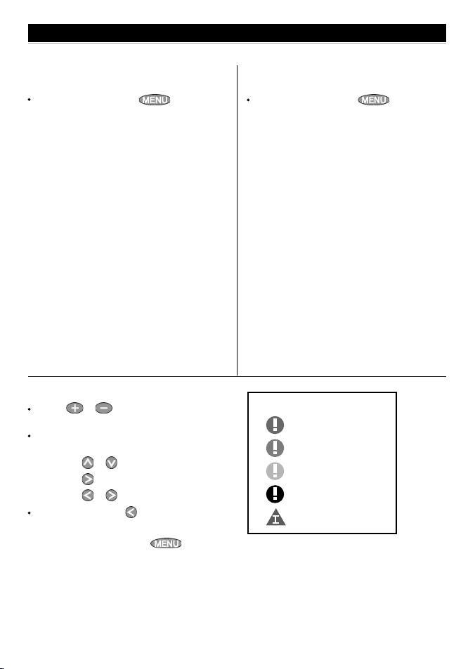
3-5 Engine fault alarms
There are many Smar tCraft engine fault alarms.
These alarms operate just like the other alarms in
the Navman instrument; when the alarm sounds,
press to mute the alarm:
Low reserve oil.
Low remote oil.
RPM over speed.
Low oil pressure.
High engine voltage.
Low engine voltage.
A Navman instrument’s low battery alarm
measures the voltage the instrument; the
above two alarms measure the voltage at the
engine.
Low block (water) pressure.
Engine overheat.
Low drive lube.
(MerCrusier stern drive only).
Water in fuel.
Engine GuardianTM active: The Engine
Guardian has detected a fault. The fault is
displayed with the alarm.
Engine communication lost: The Nav-
man instrument can not receive engine
data from the SmartCraft gateway.
Check engine: There are many other engine
fault alarms. When one of these alarms
sounds, the alarm Check engine is displayed.
For more information about the alarm,
display the list of active alarms or the alarm
history (see section 3-6).
Notes:
1 For help when an SmartCraft alarm occurs,
contact your Mercury dealer.
2 These SmartCraft alarms are always on. The
alarm values are determined by the engine
type.
3 A list of active faults and a fault history can be
displayed (see section 3-6).
12
NAVMAN
SmartCraft gateways Installation and Operation Manual
Page 11
3-6 Engine fault lists
There are two lists of SmartCraft engine faults:
1 Engine faults list
A list of active engine fault alarms.
To display the list, press until the
Setup menu is displayed, select Smart-
Craft, then select Engine faults.
2 Engine faults history
A list of nine recent engine fault alarms.
To display the list, press until the Setup menu is displayed, select SmartCraft,
then select Engine fault history.
When a faults list or history is displayed
Press or to page up and down the
list.
To display more information about a particular fault:
i Press or to select the fault.
ii Press to display the information.
iii Press or to return to the list.
To exit the list, press .
To clear the engine fault history:
1 From a main display, press until the
Setup menu is displayed.
2 Select SmartCraft, then select Reset
fault history.
SmartCraft gateways Installation and Operation Manual NAVMAN
Each engine fault has a priority:
Orange: Severe
Yellow: Warning
Black: Caution
Information
Red: Critical
13
Page 12

3-7 SmartCraft setup data
To go to the SmartCraft setup data, press
until the Setup menu is displayed, then select
SmartCraft. The setup options are:
Engine faults, Engine fault history, Reset
fault history
See section 3-6.
Troll window
Select from a menu:
On idle: Troll window is displayed when
you press and the throttle is at idle
and the engine is in gear.
Always: Troll window is displayed when you
press .
Never: Troll window never displayed, troll
control is not available.
Troll mode
Press to select what troll mode controls:
RPM: Controls engine idle RPM.
Speed: Controls engine idle RPM to try to
achieve the desired boat speed.
See section 3-3, notes 1 and 2
Trim popup
Press to select:
Off: Trim popup window is never displayed.
On: Trim popup window is displayed when
trim is changed.
Trim popup filter
This filter can stop the trim popup window appearing because of engine vibration rather than
a trim change.
Press , then press or to select a value, then
press . The values are Off and 1 to 5.
Select Off or a low value first. Run the boat at a
range of speeds and increase the value if vibration
causes the trim popup window to appear. If the
value is high, the trim window will appear slowly
when trim changes.
Speed range
Set the speed range for an analog speed gauge
(see Gauge type below). The options are High,
Me diu m and L o w. A higher range displays a
higher maximum speed but the display is more
compressed.
Speed type
Press to select the source of the water (boat)
speed reading:
Pitot: The engine’s pitot sensor.
Paddle: A Navman paddlewheel sensor.
The pitot sensor is more accurate at high speeds
but is not accurate at low speeds. The paddle wheel
sensor is more accurate at low speeds. To use troll
speed control, set Speed type to Paddle.
Pitot type
Press to select 100 psi or 200psi to match
the pitot type installed on the boat.
Gauge type
Press to select the type of gauges in the Small,
Medium and Large SmartCraft displays (see section 3-2):
Analogue: Dial displays (see also Speed
range above).
Digital: Number displays.
14
NAVMAN
SmartCraft gateways Installation and Operation Manual
Page 13

Gauge setup
Select what data is displayed in the gauges on
the three SmartCraft gauge displays. Note that
the factory default has gauges appropriate to the
type of engine.
1 To select a gauge display. Press or until
the display name (Small, Medium, Large or
Tanks) turns blue.
2 Press or to select a gauge.
3 Change the gauge:
i Press to display a menu of options for
the selected gauge (see right; the options
available will depend on your engine, see
section 1-1).
ii Press or to select an option, then
press .
4 Repeat steps 1 to 3 to change more gauges,
then press one or more times to return to
the main display.
Header setup
Select what data is displayed in the header data on
the four SmartCraft displays. The display shows the
header, with the selected data item highlit.
1 Press or to select the header item to
change.
2 Change the item:
i Press to display a menu of options for
the selected item (see right; the options
available will depend on your engine, see
section 1-1).
ii Press or to select an option, then
press .
3 Repeat steps 1 and 2 to change more header
items, then press one or more times to
return to the main display.
SmartCraft gateways Installation and Operation Manual NAVMAN
15
Page 14

3-8 SmartCraft calibration
There are three SmartCraft calibrations.
3-8-1 Tanks calibration
If tanks have level sensors fitted (see section 1-1-1),
set the type of tank, the tank alarms and calibrate
if required:
Press until the Setup menu is dis-
played, then select Calibrate, then select
Tanks.
For each tank with a level sensor, follow the
steps below:
1 Select Tank, press and select the tank
from the menu.
2 Select Tank type, press and select the
tank type from the menu (Unused, Fuel,
Water, Oil or Waste).
3 The raw level sensor data is the level in
the tank as a percentage of the level when
the tank is full (100 %). To select how the
level sensor data is displayed on the Tanks
display (see section 3-2), select Display
type, press and select the type from the
menu:
Percentage: Display the raw level sen-
sor data. Note:
If the sides of the tank are not vertical
and straight, then the Percentage
level sensor data displayed does not
correspond to the volume in the tank;
for example if the sensor shows 50 %,
the tank is not 50 % full.
For Percentage display type, fuel
Used and Remaining on the Fuel
display can not be calculated, and are
displayed as Invalid.
Volume: Display a volume calculated
linearly from the sensor data, for example
if Tank size (see below) is 500 G and
the sensor shows 50 % of full, then 250
G is displayed. Choose this option only if
the tank has vertical, straight sides and
the tank bottom and top are flat.
Calibrated volume: Display a
volume calculated non linearly from the
sensor data. Choose this option if the
tank does not have vertical, straight sides.
You must calibrate the tank (see step 6
below).
4 To set a low level alarm for the tank (see sec-
tion 3-2):
i Select Tank alarm.
ii Press to turn the alarm On or Off.
iii Press or to set the alarm value. The
alarm will sound if the alarm is On and the
tank level is less than the alarm value.
iv Finally, press .
5 Set the tank size:
i Select Tank size.
ii Press or to set the tank size.
iii Finally, press .
6 If Display type is Calibrated vol-
ume, the sensor data must be calibrated.
i Select Calibrate.
ii Follow the instructions displayed to add
measured amounts of fuel.
iii Finally, the display shows Tank size
(set in step 5 above), Actual size (the
volume of fuel you added to the tank),
and asks Is this correct? Select:
Accept to accept the calibration
16
NAVMAN
SmartCraft gateways Installation and Operation Manual
Page 15

Change to change Tank size
if Tank size is not the same as
Actual size.
3-8-2 Trim calibration
If the SmartCraft system has trim control, calibrate
the trim angle display (see section 3-4):
1 Press until the Setup menu is dis-
played, then select Calibrate, then select
Trim.
2 Select Installed and press to select
Yes.
3 Select Calibrate. Follow the instructions
displayed.
3-8-3 Steering angle calibration
If the SmartCraft system has a steering angle sensor,
it must be calibrated.
1 There must be little wind and little current.
Travel at a typical cruising speed.
2 Press until the Setup menu is
displayed, select Calibrate, then select
Steering angle.
3 Steer the boat to port. If the display needle
does not turn to port, select Polarity and
press to select the other polarity (Normal
or Inverted).
4 Steer in a straight line, then select Set
center to calibrate the steering angle.
SmartCraft gateways Installation and Operation Manual NAVMAN
17
Page 16

4 Operation with a Navman TRACKFISH 6600
Before a SmartCraft gateway is connected, the TRACKFISH 6600 functions normally, with no SmartCraft
functions. When a SmartCraft gateway is connected and SmartCraft is turned On (see section 4-1),
SmartCraft functions become available and some standard functions change.
SmartCraft functions
Data displays
Engine performance and tank level displays .............................................................................................See section 4-2
Troll control
Automatically maintains a set engine idle RPM or idle boat speed ................................................See section 4-3
Trim indicator
Displays the trim angle when engine trim is adjusted ..........................................................................See section 4-4
Alarms
Engine fault alarms ...............................................................................................................................................See section 4-5
Engine fault list, a list of active SmartCraft engine fault alarms .........................................................See section 4-6
Engine fault history, a list of past SmartCraft engine fault alarms ....................................................See section 4-6
Tank low level alarms .......................................................................................................................................See section 4-2-1
Setup data and calibrations
SmartCraft setup data ......................................................................................................................See sections 4-1 and 4-2
SmartCraft calibrations, Tanks, Trim and Steering angle .......................................................................See section 4-7
SmartCraft setup data and calibrations .....................................................................................See sections 4-7 and 4-1
The SmartCraft data available depends on the engine type and the sensors fitted (see section 1-1).
Changes to standard functions with SmartCraft enabled:
If there are no optional level sensor(s) fitted to the fuel tanks (see section 1-1-1), then the Smartcraft
If each fuel tank has an optional level sensor fitted (see section 1-1-1), then these tank levels are used
For more information, see the TRACKFISH 6600 Installation and Operation manual.
key: When using troll control, pressing can display the troll window. Press a
second time to display the normal menu.
Fuel: The fuel display functions normally but with fuel and speed data coming from the SmartCraft
system rather than from separate sensors connected to the TRACKFISH 6600.
fuel flow is used to calculate fuel remaining. The fuel setup data is the same as the standard TRACKFISH 6600. You must tell the TRACKFISH 6600 when you add or remove fuel (see the TRACKFISH 6600
Installation and Operation manual).
to calculate fuel remaining. In the Fuel display, Used changes to Trip used, and the only fuel
setup option is Clear trip used. Trip used measures the volume of fuel used until it is reset
to zero by selecting Clear trip used in the fuel setup menu. You do not tell the TRACKFISH
6600 when you add or remove fuel.
Engine hours: Engine hours on the Log display come from the SmartCraft system.
It can not be reset.
Simulate mode: Data from the SmartCraft engine(s) and sensors is simulated. The SmartCraft data
simulated will probably differ from the data available in your system.
18
NAVMAN
SmartCraft gateways Installation and Operation Manual
Page 17

4-1 Setting up the TRACKFISH 6600 for Smartcraft
There are two SmartCraft items in the TRACKFISH
6600 System setup menu. To display the System
menu, press until the Setup menu is displayed, then select System.
Sonar
Select: For normal sonar operation
De-select: To disable the sonar transducer
and sonar functions. For use
with the instrument’s SmartCraft
functions only,
SmartCraft
Select: Normal SmartCraft operation
De-select: SmartCraft functions. The instru-
ment will now use any Navman fuel
sen sors which are connected.
Note:
SmartCraft utilises NavBus comms. NavBus will
turn on if SmartCraft is turned on.
4-2 SmartCraft engine data displays
There are four SmartCraft engine displays, shown below.
Note: If the boat has twin engines, two needles will appear on most of the gauge displays. The red needle
or number shows port engine data, green shows starboard engine data.
Data header display area
Engine data display area
Small: Eight small gauges
Diagnostics: Shows
eight small gauges.
Press , select
SmartCraft, then
select Diagnostics.
SmartCraft gateways Installation and Operation Manual NAVMAN
Medium: Two medium, four
small gauges
Cruising: Shows two
large and four small
gauges. Press
, select SmartCraft,
then select Cruis-
ing.
Large: Two large gauges Tanks: Tank levels
Engine data large:
Shows two large
gauges. To display this,
press , select
SmartCraft, then
select Engine data
large.
Tank status: Shows
the levels in the tanks.
To display this, press
, select
SmartCraft, then
select Tank status.
19
Page 18

4-2-1 Tank status display
The tank level display shows the levels from the
optional level sensors in one or two tanks per
engine (see section 1-1-1).
Before use, each tank must be set up and calibrated
(see section 4-7-1).
An alarm can be set to sound if the level in a tank
is low (see section 4-7-1). These alarms are in addition to any SmartCraft engine fault low level alarms
(see section 4-5).
4-2-2 Customising the engine data
displays
To cus tomise an e ngine dat a disp lay, pre ss
, select SmartCraft, select the display
to customise, and press . Press to
display the options:
Data setup
Select the data item to be displayed in the data
header display area (at the top of the display):
1 Press , , or to select the data item
to change.
2 Select the item by pressing . this will
display a menu of options for the selected
item (the options available will depend on
your engine, see section 1-1).
Press or to select an option, then press
.
3 Repeat steps 1 and 2 to change more data
items, then press to return to the
main display.
Gauge setup
Select the data to be displayed in the engine data
display areas (not for Tank status display).
1 Press , , or to select a gauge to
change.
2 Change the gauge:
i Press to display a menu of op-
tions for the selected gauge (see right;
the options available will depend on your
engine, see section 1-1).
ii Press or to select an option, then
press .
3 Repeat steps 1 to 2 to change more gauges,
then press to return to the main
display.
Gauge type
Select the type of gauges to be displayed (not for
Tank status display):
Analogue: Dial type displays (see also sec-
tion 4-7: Speed range).
Digital: Number type displays.
Notes:
1 The factory default has gauges appropriate to
the type of engine.
2 To further customise the three gauge dis-
plays, change Speed range, Speed type
and Pitot type (see section 4-7).
20
NAVMAN
SmartCraft gateways Installation and Operation Manual
Page 19

4-3 Troll control
Troll control allows adjustment of the engine’s idle
speed from the Navman instrument. Troll control
automatically controls the engine idle speed to
maintain a set engine RPM or boat speed.
To use troll control, set Troll window to On idle
or Always and set Troll mode to Speed or RPM
(see section 4-7).
To use speed troll mode, set Speed type to Pad-
dle (see section 4-7).
To prohibit troll control, set Troll window to
Never (see section 4-7).
Engaging troll control
1 Set the throttle(s) to idle and the engine(s) in
gear. From a main display, press to
display the Troll control window (see right).
2 Press or to set the desired RPM or boat
speed (see notes 1 and 2).
3 Press to engage troll control. The
TRACKFISH 6600 automatically controls RPM
or speed. Or, press to leave troll
control disengaged.
Changing RPM or speed while troll
control engaged
1 From a main display, press to display
the troll window.
2 Press or to change the desired RPM or
boat speed (see notes 1 and 2).
3 Press
Disengaging troll control
Either move the throttle from idle, or:
1 From a main display, press to display
the troll window. Press or to select Off
(Disengage) and press
2 Or, press to leave troll control en-
gaged.
Notes:
1 The Troll range of engine idle RPM adjust-
ment available for both RPM and speed mode
depends on engine type. Generally this is
between 600 and 1000 RPM.
2 In speed troll control, the boat might not
reach the desired speed if the maximum RPM
available for troll control is too low or if conditions are bad.
3 Troll can not engage unless engine throttle(s)
are in idle, and engine(s) are in gear.
4 Troll control is not available on some Mer-
CrusierTM engines.
5 To use speed troll control, the Navman instru-
ment must have a Navman paddlewheel
speed sensor connected.
4-4 Trim indicator
When the optional engine trim is adjusted, a trim
popup window can show the new trim angle. To
see this window or not, set Trim popup to On or
Off (see section 4-7: Trim). The window will auto-
SmartCraft gateways Installation and Operation Manual NAVMAN
matically disappear after two seconds, or else press
Before use, calibrate trim (see section 4-7: Trim).
to close the window.
21
Page 20

4-5 Engine fault alarms
There are many Smar tCraft engine fault alarms.
These alarms operate just like the other alarms in
the Navman instrument; when the alarm sounds,
press to mute the alarm:
Low reserve oil.
Low remote oil.
RPM over speed.
Low oil pressure.
High engine voltage.
Low engine voltage.
A Navman instrument’s low battery alarm
measures the voltage at the instrument; the
above two alarms measure the voltage at the
engine.
Low block (water) pressure.
Engine overheat.
Low drive lube: (MerCrusier stern drive only).
Water in fuel.
Engine GuardianTM active: The Engine
4-6 Engine fault lists
There are two lists of SmartCraft engine faults:
4-6-1 Engine faults list
To display a list of active engine fault alarms: press
, select SmartCraft, then select En-
gine faults.
Guardian has detected a fault. The fault is
displayed with the alarm.
Engine communication lost: The Navman
instrument can not receive engine data from
the SmartCraft gateway.
Check engine: There are many other engine
fault alarms. When one of these alarms
sounds, the alarm Check engine is displayed.
For more information about the alarm,
display the list of active alarms or the alarm
history (see section 4-6).
Notes:
1 For help when an SmartCraft alarm occurs,
contact your Mercury dealer.
2 These SmartCraft alarms are always on. The
alarm values are determined by the engine
type.
3 A list of active faults and a fault history can be
displayed (see section 4-6).
When the faults list is displayed
Press or to page up and down the
list.
To display more information about a particular fault:
i Press or to select the fault.
ii Press to display the information.
iii Press or to return to the
list.
To exit the list, press .
Each engine fault has a priority:
Orange: Severe
Yellow: Warning
Black: Caution
Information
22
NAVMAN
Red: Critical
SmartCraft gateways Installation and Operation Manual
Page 21

4-6-2 Engine fault history
To display a list of recent engine fault alarms, press
, select SmartCraft, then select En-
gine fault history.
When the Engine fault history is displayed
Press or to page up and down the
list.
To display more information about a particular fault:
i Press or to select the fault.
ii Press to display the information.
iii Press or to return to the
list.
To exit the list, press .
To clear the engine fault history:
Go to the engine fault history display, press
and select Reset fault his-
tory.
4-7 SmartCraft setup data and calibrations
To go to the SmartCraft setup data and calibrations,
press until the Setup menu is displayed,
then select SmartCraft.
Note:
If there is more than one SmartCraft capable Navman instrument in a system, some setup data may
be different in each instrument.
SmartCraft gateways Installation and Operation Manual NAVMAN
The setup and calibration options are:
Tanks
Set up and calibrate the tanks (see section 4-7-1).
Troll window
Select from a menu:
On idle: Troll window is displayed when you
press and the throttle is at idle and the
engine is in gear.
Always: Troll window is displayed when you
press .
Never: Troll window never displayed, troll
control is not available.
Troll mode
Select what troll mode controls:
RPM: Controls engine idle RPM.
Speed: Controls engine idle RPM to try to
achieve the desired boat speed.
See section 4-3, notes 1 and 2
Trim
Set up and calibrate the trim display (see section 4-7-2).
23
Page 22

Steering angle
Set up and calibrate the steering angle (see section 4-7-3).
Speed range
Set the speed range for an analog speed gauge.
The options are High, Medium and Low. A higher
range displays a higher maximum speed but the
display is more compressed.
Speed type
Select the source of the water (boat) speed reading:
Pitot: The engine’s pitot sensor.
Paddle: A Navman paddlewheel sensor.
The pitot sensor is more accurate at high speeds
but is not accurate at low speeds. The paddlewheel
sensor is more accurate at low speeds. To use troll
speed control, set Speed type to Paddle.
Pitot type
Press to select 100 psi or 200psi to match
the pitot type installed on the boat.
4-7-1 Tanks setup and calibration
Set up and calibrate tanks with level sensors fitted
(see section 1-1-1):
1 Press until the Setup menu is
displayed, select SmartCraft, then select
Tanks.
2 For each tank in the boat, select Tank, select
the tank to set up, then set up and calibrate
the tank.
Note:
The displayed Tank size unit uses the setting selected in the Navman instrument. To change to a
different unit type, use the Setup > Units menu in
the Navman instrument.
For each tank, the options are:
Tank type
Select the tank type (Unused, Fuel, Water, Oil
or Waste).
Display type
The data from the level sensor in each tank is the
depth in the tank as a percentage of the depth when
the tank is full. If the sides of the tank are not vertical
and straight, or if the tank top and bottom are not
flat, then the level sensor data does not correspond
to the volume in the tank; for example if the sensor
shows 50 %, the tank is not 50 % full.
The Display type option selects how the level
sensor data is displayed:
Percentage: Display the percentage level
sensor data. The default is the percentage
level sensor data. If the tank is calibrated, then
a calibrated percentage is displayed.
Volume: Display a volume calculated from
the sensor data. The default is a linear calculation, for example if the tank holds 500 G and
the sensor shows 50 % of full, then 250 G is
displayed. This is correct if the sides of the
tank are vertical and straight and the tank top
and bottom are flat. If this is not so, calibrate
the tank (see Calibrate below).
Tank size
Set the tank size:
i Set the tank size: press or to select a
digit, then press or to change the digit.
ii Press .
Tank alarm
To set a low level alarm for the tank:
i Set the alarm value: press or to select a
digit, then press or to change the digit.
To turn the alarm off, set the alarm value to
0. If the alarm value is greater than zero, the
alarm will sound if the tank level is less than
the alarm value.
ii Press .
Calibrate
Calibrate the tank readings if the sides of the tank
are not ver tical and straight, or if the tank top
and bottom are not flat. The following procedure
requires the tank to be filled from empty. The
24
NAVMAN
SmartCraft gateways Installation and Operation Manual
Page 23

Tank Calibration screen will display an amount of
fuel to add to the tank - select OK each time the
measured amount is added. This will happen a
number of times.
i Enter the tank size (volume).
ii Follow the on-screen instructions displayed
to add measured amounts of fuel. Select OK
each time the measured amount is added.
iii The display shows Tank calibration
- Tank profile and asks Is this cor-
4-7-2 Trim setup and calibration
Set up and calibrate a SmartCraft trim control (see
section 4-4). Press until the Setup menu is
displayed, then select SmartCraft, then select
Trim. The options are:
Installed
Select: Trim sensors are installed in the
engine(s).
De-select: No trim sensors installed in the
engine(s).
rect?.
Select:
OK to accept the calibration
Cancel to cancel.
iv. If the actual tank size did not match that in
step (i), then change the tank size from
the menu.
Reset calibration
Reset the tank calibration to the default - the displayed volume is calculated linearly from the sensor
data (see Display type above). Any tank calibration
data will be lost.
Trim popup
Select: Trim sensors are installed in the
engine(s).
De-select: Trim popup window is never
displayed.
Trim popup f ilter
This filter can stop the trim popup window appearing because of engine vibration rather than
a trim change.
Press , then press or to select a
value, then press . The values are Off
and 1 to 5.
Select Off or a low value first. Run the boat at a
range of speeds and increase the value if vibration
causes the trim popup window to appear. If the
value is high, the trim window will appear slowly
when trim changes.
Calibrate
Follow the on-screen instructions displayed to calibrate the displayed trim angle, and press
as required.
SmartCraft gateways Installation and Operation Manual NAVMAN
25
Page 24

4-7-3 Steering angle setup and
calibration
Set up and calibrate the SmartCraft steering angle
display. Press until the Setup menu is
displayed, then select SmartCraft, then select
Steering angle. The options are:
Installed
Select: Steering angle sensor installed.
De-select: No steering angle sensor installed.
Polarity
Steer the boat to port. If the steering angle pointer
does not move to port, choose the other polarity
(Normal or Inverted).
Calibrate
1 There must be little wind and little current.
Travel at a typical cruising speed.
2 Steer in a straight line, then select Cali-
brate to calibrate the steering angle.
3 Press enter when steering in a straight line.
26
NAVMAN
SmartCraft gateways Installation and Operation Manual
Page 25

5 Operation with a Navman FISH 4600
Before a SmartCraft gateway is connected, the FISH 4600 functions normally, with no SmartCraft functions.
When a SmartCraft gateway is connected and SmartCraft is turned On (see section 5-1), SmartCraft
functions become available and some standard functions change.
SmartCraft functions
Data displays
Engine performance and tank level displays .............................................................................................See section 5-2
Troll control
Automatically maintains a set engine idle RPM or idle boat speed ................................................See section 5-3
Trim indicator
Displays the trim angle when engine trim is adjusted ..........................................................................See section 5-4
Alarms
SmartCraft engine fault alarms ........................................................................................................................See section 5-5
Engine fault list, a list of active SmartCraft engine fault alarms .........................................................See section 5-6
Engine fault history, a list of past SmartCraft engine fault alarms ....................................................See section 5-6
Tank low level alarms .......................................................................................................................................See section 5-2-1
Setup data and calibrations
SmartCraft setup data ......................................................................................................................See sections 5-6 and 5-8
SmartCraft calibrations, Tanks, Trim and Steering angle .......................................................................See section 5-7
SmartCraft setup data and calibrations .....................................................................................See sections 5-7 and 5-1
The SmartCraft data available depends on the engine type and the sensors fitted (see section 1-1).
Changes to standard functions with SmartCraft enabled:
If there are no optional level sensor(s) fitted to the fuel tanks (see section 1-1-1), then the Smartcraft
If each fuel tank has an optional level sensor fitted (see section 1-1-1), then these tank levels are used
For more information, see the FISH 4500/4600 Installation and Operation manual.
key: When using troll control, pressing can display the troll window. Press a
second time to display the normal menu.
Fuel: The fuel display functions normally but with fuel and speed data coming from the SmartCraft
system rather than from separate sensors connected to the FISH 4600.
fuel flow is used to calculate fuel remaining. The fuel setup data is the same as the standard FISH
4600. You must tell the FISH 4600 when you add or remove fuel (see the FISH 4500/4600 Installation
and Operation manual).
to calculate fuel remaining. In the Fuel display, Used changes to Trip used, and the only fuel
setup option is Clear trip used. Trip used measures the volume of fuel used until it is reset
to zero by selecting Clear trip used in the fuel setup menu. You do not tell the FISH 4600 when
you add or remove fuel.
Engine hours: Engine hours on the Log display come from the SmartCraft system.
It can not be reset.
Simulate mode: Data from the SmartCraft engine(s) and sensors is simulated. The SmartCraft data
simulated will probably differ from the data available in your system.
SmartCraft gateways Installation and Operation Manual NAVMAN
27
Page 26

5-1 Setting up the FISH 4600 for Smartcraft
There are two SmartCraft items in the FISH 4600
System setup menu. To display the System menu,
press until the Setup menu is displayed,
then select System.
Sonar
Select: For normal sonar operation
De-select: To disable the sonar transducer
and sonar functions. For use
with the instrument’s SmartCraft
functions only,
SmartCraft
Select: Normal SmartCraft operation
De-select: SmartCraft functions. The instru-
ment will now use any Navman
fuel sensors which are connected.
Note:
SmartCraft utilises NavBus comms. NavBus will
turn on if SmartCraft is turned on.
5-2 SmartCraft engine data displays
There are four SmartCraft engine displays, shown below.
Note: If the boat has twin engines, two needles will appear on most of the gauge displays. The red needle
or number shows port engine data, green shows starboard engine data.
Engine data display area
Data header display area
Small: Eight small gauges
Shows eight small
gauges. Press
, select SmartCraft,
then select Small.
28
Medium: Two medium, four
small gauges
Shows two large and
four small gauges.
Press , select
SmartCraft, then
select Medium.
NAVMAN
Large: Two large gauges Tanks: Tank levels
Shows two large
gauges. To display this,
press , select
SmartCraft, then
select Large.
SmartCraft gateways Installation and Operation Manual
Shows the levels in the
tanks. To display this,
press , select
SmartCraft, then
select Tanks.
Page 27

5-2-1 Tank status display
The tank level display shows the levels from the
optional level sensors in one or two tanks per
engine (see section 1-1-1).
Before use, each tank must be set up and calibrated
(see section 5-7-1).
An alarm can be set to sound if the level in a tank
is low (see section 5-7-1). These alarms are in addition to any SmartCraft engine fault low level alarms
(see section 5-5).
3 Repeat steps 1 to 2 to change more gauges,
5-2-2 Customising the engine data
displays
To customise an engine data display, press
select SmartCraft, select the display to custom-
ise. Press to display the available options;
Gauge type, Gauge setup, and Header setup, then
press
.
Gauge type
Select the type of gauges to be displayed (not for
Tank status display):
Analogue: Dial type displays (see also sec-
tion 5-7: Speed range).
Digital: Number type displays.
Notes:
1 The factory default has gauges appropriate to
the type of engine.
2 To further customise the three gauge dis-
plays, change Speed range, Speed type
and Pitot type (see section 5-7)
Gauge setup
Select the data to be displayed in the engine data
display areas (not for Tank status display).
1 Press , , or to select a gauge to
change.
2 Change the gauge:
i Press
tions for the selected gauge (see above;
the options available will depend on your
engine, see section 1-1).
SmartCraft gateways Installation and Operation Manual NAVMAN
to display a menu of op-
,
Header setup
Select the data item to be displayed in the data
header display area (at the top of the display):
1 Press , , or to select the data item
2 Select the item by pressing
3 Repeat steps 1 and 2 to change more data
ii Press or to select an option, then
press .
then press
display.
to change.
display a menu of options for the selected
item (the options available will depend on
your engine, see section 1-1).
Press or to select an option, then press
items, then press to return to the
main display.
to return to the main
. this will
.
29
Page 28

5-3 Troll control
Troll control allows adjustment of the engine’s idle
speed from the Navman instrument. Troll control
automatically controls the engine idle speed to
maintain a set engine RPM or boat speed.
To use troll control, set Troll window to On idle
or Always and set Troll mode to Speed or RPM
(see section 5-7).
To use speed troll mode, set Speed type to Pad-
dle (see section 5-7).
To prohibit troll control, set Troll window to
Never (see section 5-7).
Engaging troll control
1 Set the throttle(s) to idle and the engine(s) in
gear. From a main display, press to
display the Troll control window (see right).
2 Press or to set the desired RPM or boat
speed (see notes 1 and 2).
3 Press
FISH 4600 automatically controls RPM or
speed. Or, press to leave troll control
disengaged.
Changing RPM or speed while troll
control engaged
1 From a main display, press to display
the troll window.
2 Press or to change the desired RPM or
boat speed (see notes 1 and 2).
3 Press
Disengaging troll control
Either move the throttle from idle, or:
1 From a main display, press to display
the troll window. Press or to select Off
(Disengage) and press
2 Or, press to leave troll control en-
gaged.
to engage troll control. The
Notes:
1 The Troll range of engine idle RPM adjust-
ment available for both RPM and speed mode
depends on engine type. Generally this is
between 600 and 1000 RPM.
2 In speed troll control, the boat might not
reach the desired speed if the maximum RPM
available for troll control is too low or if conditions are bad.
3 Troll can not engage unless engine throttle(s)
are in idle, and engine(s) are in gear.
4 Troll control is not available on some Mer-
CrusierTM engines.
5 To use speed troll control, the Navman instru-
ment must have a Navman paddlewheel
speed sensor connected.
5-4 Trim indicator
When the optional engine trim is adjusted, a trim
popup window can show the new trim angle. To
see this window or not, set Trim popup to On or
Off (see section 5-7: Trim). The window will automatically disappear after two seconds, or else press
30
NAVMAN
to close the window.
Before use, calibrate trim (see section 5-7: Trim).
SmartCraft gateways Installation and Operation Manual
Page 29

5-5 Engine fault alarms
There are many Smar tCraft engine fault alarms.
These alarms operate just like the other alarms in
the Navman instrument; when the alarm sounds,
press to mute the alarm:
Low reserve oil.
Low remote oil.
RPM over speed.
Low oil pressure.
High engine voltage.
Low engine voltage.
A Navman instrument’s low battery alarm
measures the voltage at the instrument; the
above two alarms measure the voltage at the
engine.
Low block (water) pressure.
Engine overheat.
Low drive lube (MerCrusier stern drive only).
Water in fuel.
Engine GuardianTM active: The Engine
5-6 Engine fault lists
There are two lists of SmartCraft engine faults:
5-6-1 Engine faults list
To display a list of active engine fault alarms: press
, select SmartCraft, then select Engine
faults.
Guardian has detected a fault. The fault is
displayed with the alarm.
Engine communication lost: The Navman
instrument can not receive engine data from
the SmartCraft gateway.
Check engine: There are many other engine
fault alarms. When one of these alarms
sounds, the alarm Check engine is displayed.
For more information about the alarm,
display the list of active alarms or the alarm
history (see section 5-6).
Notes:
1 For help when an SmartCraft alarm occurs,
contact your Mercury dealer.
2 These SmartCraft alarms are always on. The
alarm values are determined by the engine
type.
3 A list of active faults and a fault history can be
displayed (see section 5-6).
When the faults list is displayed
Press or to page up and down the
list.
To display more information about a particular fault:
i Press or to select the fault.
ii Press to display the information.
iii Press
list.
To exit the list, press .
or to return to the
Each engine fault has a priority:
Orange: Severe
Yellow: Warning
Black: Caution
Information
SmartCraft gateways Installation and Operation Manual NAVMAN
Red: Critical
31
Page 30

5-6-2 Engine fault history
To display a list of recent engine fault alarms, press
, select SmartCraft, then select En-
gine fault history.
When the Engine fault history is displayed
Press or to page up and down the
list.
To display more information about a particular fault:
i Press or to select the fault.
ii Press
iii Press
list.
To exit the list, press .
To clear the engine fault history:
Go to the engine fault history display, press
tory.
to display the information.
or to return to the
and select Reset fault his-
5-7 SmartCraft setup data and calibrations
To go to the SmartCraft setup data and calibrations,
press until the Setup menu is displayed,
then select SmartCraft.
Note:
If there is more than one SmartCraft capable Navman instrument in a system, some setup data may
be different in each instrument.
32
The setup and calibration options are:
Tanks
Set up and calibrate the tanks (see section 5-7-1).
Troll window
Select from a menu:
On idle: Troll window is displayed when you
press and the throttle is at idle and the
engine is in gear.
Always: Troll window is displayed when you
press .
Never: Troll window never displayed, troll
control is not available.
Troll mode
Select what troll mode controls:
RPM: Controls engine idle RPM.
Speed: Controls engine idle RPM to try to
achieve the desired boat speed.
See section 5-3, notes 1 and 2
Trim
Set up and calibrate the trim display (see section 5-7-2).
NAVMAN
SmartCraft gateways Installation and Operation Manual
Page 31

Steering angle
Set up and calibrate the steering angle (see section 5-7-3).
Speed range
Set the speed range for an analog speed gauge.
The options are High, Medium and Low. A higher
range displays a higher maximum speed but the
display is more compressed.
Speed type
Select the source of the water (boat) speed reading:
Pitot: The engine’s pitot sensor.
Paddle: A Navman paddlewheel sensor.
The pitot sensor is more accurate at high speeds
but is not accurate at low speeds. The paddlewheel
sensor is more accurate at low speeds. To use troll
speed control, set Speed type to Paddle.
Pitot type
Press to select 100 psi or 200psi to match
the pitot type installed on the boat.
5-7-1 Tanks setup and calibration
Set up and calibrate tanks with level sensors fitted
(see section 1-1-1):
1 Press until the Setup menu is
displayed, select SmartCraft, then select
Tanks.
2 For each tank in the boat, select Tank, select
the tank to set up, then set up and calibrate
the tank.
Note:
The displayed Tank size unit uses the setting selected in the Navman instrument. To change to a
different unit type, use the Setup > Units menu in
the Navman instrument.
For each tank, the options are:
Tank type
Select the tank type (Unused, Fuel, Water, Oil
or Waste).
Display type
The data from the level sensor in each tank is the
depth in the tank as a percentage of the depth when
the tank is full. If the sides of the tank are not vertical
and straight, or if the tank top and bottom are not
flat, then the level sensor data does not correspond
to the volume in the tank; for example if the sensor
shows 50 %, the tank is not 50 % full.
The Display type option selects how the level
sensor data is displayed:
Percentage: Display the percentage level
sensor data. The default is the percentage
level sensor data. If the tank is calibrated, then
a calibrated percentage is displayed.
Volume: Display a volume calculated from
the sensor data. The default is a linear calculation, for example if the tank holds 500 G and
the sensor shows 50 % of full, then 250 G is
displayed. This is correct if the sides of the
tank are vertical and straight and the tank top
and bottom are flat. If this is not so, calibrate
the tank (see Calibrate below).
Tank size
Set the tank size:
i Set the tank size: press or to select a
digit, then press or to change the digit.
ii Press
.
Tank alarm
To set a low level alarm for the tank:
i Set the alarm value: press or to select a
digit, then press or to change the digit.
To turn the alarm off, set the alarm value to
0. If the alarm value is greater than zero, the
alarm will sound if the tank level is less than
the alarm value.
ii Press .
SmartCraft gateways Installation and Operation Manual NAVMAN
33
Page 32

Calibrate
Calibrate the tank readings if the sides of the tank
are not ver tical and straight, or if the tank top
and bottom are not flat. The following procedure
requires the tank to be filled from empty. The
Tank Calibration screen will display an amount of
fuel to add to the tank - select OK each time the
measured amount is added. This will happen a
number of times.
i Enter the tank size (volume).
Reset calibration
Reset the tank calibration to the default - the displayed volume is calculated linearly from the sensor
data (see Display type above). Any tank calibration
data will be lost.
5-7-2 Trim setup and calibration
Set up and calibrate a SmartCraft trim control (see
section 5-4). Press until the Setup menu is
displayed, then select SmartCraft, then select
Trim. The options are:
ii Follow the on-screen instructions displayed
to add measured amounts of fuel. Select OK
each time the measured amount is added.
iii The display shows Tank calibration
- Tank profile and asks Is this cor-
rect?.
Select:
OK to accept the calibration
Cancel to cancel.
iv. If the actual tank size did not match that in
step (i), then change the tank size from
the menu.
34
NAVMAN
Installed
Select: Trim sensors are installed in the
engine(s).
De-select: No trim sensors installed in the
engine(s).
Trim popup
Select: Trim sensors are installed in the
engine(s).
De-select: Trim popup window is never
displayed.
Trim popup f ilter
This filter can stop the trim popup window appearing because of engine vibration rather than
a trim change.
Press
value, then press . The values are Off
and 1 to 5.
Select Off or a low value first. Run the boat at a
range of speeds and increase the value if vibration
causes the trim popup window to appear. If the
value is high, the trim window will appear slowly
when trim changes.
, then press or to select a
Calibrate
Follow the on-screen instructions displayed to calibrate the displayed trim angle, and press
as required.
SmartCraft gateways Installation and Operation Manual
Page 33

5-7-3 Steering angle setup and
calibration
Set up and calibrate the SmartCraft steering angle
display. Press until the Setup menu is
displayed, then select SmartCraft, then select
Steering angle. The options are:
Installed
Select: Steering angle sensor installed.
De-select: No steering angle sensor installed.
Polarity
Steer the boat to port. If the steering angle pointer
does not move to port, choose the other polarity
(Normal or Inverted).
Calibrate
1 There must be little wind and little current.
Travel at a typical cruising speed.
2 Steer in a straight line, then select Cali-
brate to calibrate the steering angle.
3 Press enter when steering in a straight line.
SmartCraft gateways Installation and Operation Manual NAVMAN
35
Page 34

Appendix A - Specifications
Physical
Size 130 x 62 x 26 mm (5.1 x 2.4 x 1.0 in).
Operating temperature 0 to 50°C (32 to
122°F).
Built-in cable to the Navman instrument, 1 m
(3.3 ft) long.
Built-in cable to SmartCraft and engine, 300
mm (1 ft) long.
Electrical
Power supply 9.0 to 30 V DC, 50 mA.
Interfaces
NavBus connection to Navman instruments.
CAN bus connection to SmartCraft system.
Standards compliance
EMC compliance
USA (FCC): Part 15 Class B.
Europe (CE): EN50081-1,EN50082-1,
EN55024, EN55022, ISO7637-1.
New Zealand and Australia (C Tick) : AS-NZS
3548.
Appendix B - Troubleshooting
1 No S martCr aft functio ns avai labl e or
SmartCraft data is zero or is not displayed
a Boat engine key is off.
b Review installation; check the gateway LEDs
are working (see section 2)
c SmartCraft is disabled in the Navman Instru-
ment. See Setup > System menu.
2 Some SmartCraft data is not available:
The data available depends on engine type
(see section 1-1).
3 Can not start troll control:
a Some MerCruiser engines do not support troll
control.
b Set engine to idle and in gear (see section
Troll Control).
c Set Speed type to Paddle (see section
Troll Control).
d To use speed troll control, the Navman instru-
Cable to Navman instrument
Wire Signal
Red Power positive, 9 to 30 V DC,
50 mA
Black Power negative
Brown Power positive from instrument
Orange NavBus +
Blue NavBus Green No connection
Yellow No connection
White No Connection
ment must have a Navman paddlewheel
speed sensor connected.
4 Trim window is slow to appear, or appears
when trim does not change:
Change the trim filter (see sectionTrim Setup
and Calibration).
36
NAVMAN
SmartCraft gateways Installation and Operation Manual
Page 35

Appendix C - Mercury SmartCraft accessories
859318T1
Termination resistor
8784924
SmartCraft junction box
– 4 way
879968T (6, 10, 15, 20, 30)
SmartCraft wiring harness
892452A01
Smartcraft cable adaptor
(male/male)
8784926
SmartCraft junction box
– 6 way
879981T (10,15, 20, 30)
SmartCraft wiring harness with
1 terminator
892453A01
SmartCraft cable adaptor
(female/female)
8784928
SmartCraft junction box
– 8 way
879982T (20, 30)
SmartCraft wiring harness with
2 terminators
859743T2
SmartCraft accessory
harness (fuel/oil)
SmartCraft gateways Installation and Operation Manual NAVMAN
859318T2
SmartCraft weather cap
37
Page 36

Appendix D How to contact us www.navman.com
NORTH AMERICA
BNT - Marine Electronics
30 Sudbury Rd, Acton, MA 01720.
Toll Free: +1 866 628 6261
Fax: +1 978 897 8264
e-mail: sales@navmanusa.com
web: www.navman.com
OCEANIA
Australia
Navman Australia Pty. Limited
Suite 2, 408 Victoria Road
Gladesville NSW 2111, Australia.
Ph: +61 2 9879 9000
Fax: +61 2 9879 9001
e-mail: sales@navman.com.au
web: www.navman.com
New Zealand
Absolute Marine Ltd.
Unit B, 138 Harris Road,
East Tamaki, Auckland.
Ph: +64 9 273 9273
Fax: +64 9 273 9099
e-mail: navman@absolutemarine.co.nz
Papua New Guinea
Lohberger Engineering,
Lawes Road, Konedobu.
PO Box 810, Port Moresby.
Ph: +675 321 2122
Fax: +675 321 2704
e-mail: loheng@online.net.pg
web: www.lohberger.com.pg
LATIN AMERICA
Argentina
Costanera Uno S.A.
Av Pte Ramón S. Castillo y Calle 13
Zip 1425 Buenos Aires, Argentina.
Ph: +54 11 4312 4545
Fax +54 11 4312 5258
e-mail:
purchase@costanerauno.com.ar
web: www.costanerauno.ar
Brazil
Equinautic Com Imp Exp de Equip
Nauticos Ltda.
Rua Ernesto Paiva, 139
Clube dos Jangadeiros
Porto Alegre - RS - Brasil
CEP: 91900-200.
Ph: +55 51 3268 6675
+55 51 3269 2975
Fax: +55 51 3268 1034
e-mail:
equinautic@equinautic.com.br
web: www.equinautic.com.br
Realmarine
Estrada do Joa 3862,
Barra da Tijuca, Rio de Janeiro, Brazil.
CEP: 22611-020.
Ph: +55 21 2483 9700
Fax: +55 21 2495 6823
e-mail: tito@realmarine.com.br
web: www.realmarine.com.br
Chile
Equimar
Manuel Rodrigurez 27
Santiago, Chile.
Ph: +56 2 698 0055
Fax +56 2 698 3765
e-mail: mmontecinos@equimar.cl
Mera Vennik
Colon 1148, Talcahuano,
4262798, Chile.
Ph: +56 41 541 752
Fax +56 41 543 489
e-mail: meravennik@entel.chile.net
Mexico
Mercury Marine de Mexico
Anastacio Bustamente #76
Interior 6 C olonia Fr ancisco Za rabia,
Zapapan, Jalisco, C.P. 45236 Mexico.
Ph: +52 33 3283 1030
Fax: +52 33 3283 1034
web: www.equinautic.com.br
Uruguay
Alvaro Bermudez, Nautica
11300 Montevideo, Uruguay.
Ph & Fax: +59 82 628 6562
e-mail: alvaro@nautica.com.uy
ASIA
China
Peaceful Marine Electronics Co. Ltd.
Guangzhou, Hong Kong, Dalian,
Qingdao, Shanghai
1701 Yanjiang Building
195 Yan Jiang Zhong Rd. 510115
Guangzhou, China.
Ph: +86 20 3869 8839
Fax: +86 20 3869 8780
e-mail: sales@peaceful-marine.com
web: www.peaceful-marine.com
India
Access India Overseas Pvt. Ltd.
A-98, Sector 21,
Noida - 201 301, India.
Ph: +91 120 244 2697
TeleFax: +91 120 253 7881
Mobile: +91 98115 04557
e-mail: vkapil@del3.vsnl.net.in
Esmario Export Enterprises
Block No. F-1, 3rd Floor, Surya Towers
Sardar Patel Rd, Secunderbad 500 003.
Ph: +91 40 2784 5163
Fax: +91 40 2784 0595
e-mail: gjfeee@hd1.vsnl.net.in
web: www.esmario.com
Korea
Kumhomarine Technology Co. Ltd.
#604-842, 2F, 1118-15, Janglim1-Dong,
Saha-Gu, Busan, Korea.
Ph: +82 51 293 8589
Fax: +82 51 265 8984
e-mail: info@kumhomarine.com
web: www.kumhomarine.com
Maldives
Maizan Electronics Pte. Ltd.
Henveyru, 08 Sosunmagu.
Male', Maldives.
Mobile: +960 78 24 44
Ph: +960 32 32 11
Fax: +960 32 57 07
e-mail: ahmed@maizan.com.mv
Singapore and Malaysia, Brunei,
Indonesia and Phillipines
RIQ PTE Ltd.
Blk 3007, 81 Ubi Road 1, #02-440,
Singapore 408701.
Ph: +65 6741 3723
Fax : +65 6741 3746
e-mail: riq@postone.com
Taiwan
Seafirst International Corporation
No. 281, Hou-An Road, Chien-Chen
Dist. Kaohsiung, Taiwan R.O.C.
Ph: +886 7 831 2688
Fax: +886 7 831 5001
e-mail: seafirst@seed.net.tw
web: www.seafirst.com.tw
Thailand
Thong Electronics (Thailand) Co. Ltd.
923/588 Ta Prong Road, Mahachai,
Muang, Samutsakhon 74000, Thailand.
Ph: +66 34 411 919
Fax: +66 34 422 919
e-mail: sales@thongelectronics.com
admins@thongelectronics.com
web: www.thongelectronics.com
Vietnam
HaiDang Co. Ltd.
763 Le Hong Phong St. Ward 12
District 10, Hochiminh City, Vietnam
Ph: +84 8 863 2159
Fax: +84 8 863 2524
e-mail: haidang-co@hcm.vnn.vn
web: www.haidangvn.com
MIDDLE EAST
Lebanon and Syria
Balco Stores
Balco Building, Moutran Street,
Tripoli (via Beirut). - Lebanon
P.O. Box: 622.
Ph: +961 6 624 512
Fax: +961 6 628 211
e-mail: balco@cyberia.net.lb
United Arab Emirates
Kuwait, Oman, Iran, Saudi
Arabia, Bahrain and Qatar
Abdullah Moh’d Ibrahim Trading, opp
Creak Rd. Baniyas Road, Dubai.
Ph: +971 4 229 1195
Fax: +971 4 229 1198
e-mail: sales@amitdubai.com
AFRICA
South Africa
Pertec (Pty) Ltd (Coastal Division)
16 Paarden Eiland Road.
Paarden Eiland, 7405
PO Box 527,
Paarden Eiland, 7420
Cape Town, So uth Africa.
Ph: +27 21 508 4707
Fax: +27 21 508 4888
e-mail: info@kfa.co .za
web: www.pertec.co.za
EUROPE
France, Belgium and Switzerland
Plastimo International
15, rue Ingénieur Verrière,
BP435,
56325 Lorient Cedex.
Ph: +33 2 97 87 36 36
Fax: +33 2 97 87 36 49
e-mail: plastimo@plastimo.fr
web: www.plastimo.fr
Germany
Navimo Deutschland
15, rue Ingénieur Verrière
BP435- 56325 Lorient Cedex.
Ph: +49 6105 92 10 09
+49 6105 92 10 10
+49 6105 92 10 12
Fax: +49 6105 92 10 11
e-mail:
plastimo.international@plastimo.fr
website: www.plastimo.de
Italy
Navimo Italia
Nuova Rade spa, Via del Pontasso 5
16015 Casella Scrivia (GE).
Ph: +39 1096 80162
Fax: +39 1096 80150
e-mail: info@nuovarade.com
web: www.plastimo.it
Holland
Navimo Holland
Industrieweg 4,
2871 JE Schoonhoven.
Ph: +31 182 320 522
Fax: +31 182 320 519
e-mail: info@plastimo.nl
web: www.plastimo.nl
United Kingdom
Navimo UK
Hamilton Business Park
Bailey Road, Hedge End
Southhampton, Hants S030 2HE.
Ph: +44 01489 778 850
Fax: +44 0870 751 1950
e-mail: sales@plastimo.co.uk
web: www.plastimo.co.uk
Sweden, Denmark, Finland and
Norway
Navimo Nordic
Lundenvägen 2,
473 21 Henån.
Ph: +46 304 360 60
Fax: +46 304 307 43
e-mail: info@plastimo.se
web: www.plastimo.se
Spain
Navimo España
Polígono Industrial de Cabrera
Plaza Industria, S/N
08349 Cabrera de Mar
Barcelona.
Ph: +34 93 750 75 04
Fax: +34 93 750 75 34
e-mail: plastimo@plastimo.es
web: www.plastimo.es
Portugal
Navimo Portugal
Avenida de India N°40
1300-299 Lisbon.
Ph: +351 21 362 04 57
Fax: +351 21 362 29 08
e-mail: plastimo@siroco-nautica.pt
web: www.plastimo.com
Other countries in Europe
Plastimo International
15, rue Ingénieur Verrière BP435
56325 Lorient Cedex, France.
Ph: +33 2 97 87 36 59
Fax: +33 2 97 87 36 29
e-mail:
plastimo.international@plastimo.fr
web: www.plastimo.com
HEADQUARTERS
Navman NZ Limited
13-17 Kawana St.
Northcote.
P.O. Box 68 155,
Newton,
Auckland,
New Zealand.
Ph: +64 9 481 0500
Fax: +64 9 481 0590
e-mail: marine.sales@navman.com
web: www.navman.com
38
NAVMAN
SmartCraft gateways Installation and Operation Manual
 Loading...