

Page 1

M165939M.2
ITEM NUMBER: 165939
®
Owner’s Manual
Instructions for Installation/Set-up, Operation, Servicing, & Storage
Portable, Outdoor Use-Only, Triple Fuel Generator
SERIAL NUMBER: _____________
10,500 Watt Continuous (13,000 Watt Surge) Capacity
Can be used to power individual appliances plugged directly into the generator’s outlets, or as a
back-up connection to a building’s power supply (via a professionally installed UL-approved
transfer switch.
WARNING
READ and UNDERSTAND this manual completely before using the generator! Failure to properly set up,
operate, and maintain this generator could result in serious injury or death from carbon monoxide poisoning,
electric shock, fire/explosion, or burns. In particular, be aware of the following hazards:
Generators give off carbon monoxide, a poisonous gas that can kill you. You CANNOT smell it, see it, or taste it.
• ONLY run generator OUTDOORS and AWAY from building air intakes. NEVER run generator inside any enclosed or
semi-enclosed spaces, including homes, basements, garages, sheds , boxes , RVs, boats or pick-up truck beds. These
spaces can trap poisonous gases, EVEN if you run a fan or open windows.
• Carbon monoxide is given off whether you are using gasoline, natural gas, or propane to powe r the ge nerator.
• Install carbon monoxide alarms inside nearby struct u res/b ui l di n gs (batt e r y -o perat ed , or pl u g-in with battery backup).
Electric shock / Electrocution
• High voltage electricity from generator can kill. DO NOT operate in wet locations. Be sure generator is properly
grounded. Use only UL-listed, outdoor-rated grounded extension cords of proper size.
• NEVER plug the generator directly into a wall outlet. ANY connection to a building’s electrical system MUST
ISOLATE THE GENERATOR FROM UTILITY POWER via a UL-approved transfer switch installed by a licensed
electrician. Otherwise, back feed from the generator into the power grid could kill utility workers.
• DO NOT overload generator (per rated capacity), and OPERATE ONLY in an area with adequate cooling ventilation so
engine does not overheat. Exhaust can be extremely hot. Keep muffler at least 7’ from all combustible objects.
• All fuels are flammable. Never fuel a running or hot engine. Never pump fuel directly into generator at gas station – use
approved container to transfer fuel. Ensure there are no fuel leaks, and keep sources of sparks and flames away.
• LPG/NG hook-ups must be completed by a certified gas technician and comply with all federal and local requirements.
• ALWAYS keep a fire extinguisher rated “ABC” nearby.
CO Poisoning
Fire / Explosion
STOP!
CHOOSE THE RIGHT GENERATOR FOR YOUR NEEDS. See the “Power load Planning & Management” section
of this manual to determine your power load requirements and then compare to the generator’s rated capacity.
INSPECT COMPONENTS: Closely inspect to make sure no components are missing or damaged. See the “Unpacking
& Delivery Inspection” section for instructions on whom to contact to report missing or damaged parts.
ARRANGE FOR PROFESSIONAL INSTALLATION of transfer switch and/or NG/LPG hook-ups, if they will be used.
See the “Installation/Initial Set-Up” section for more information about these requirements.
Any Questions, Comments, Problems, or Parts Orders
Call NorthStar Product Support 1-800-270-0810
Page 2
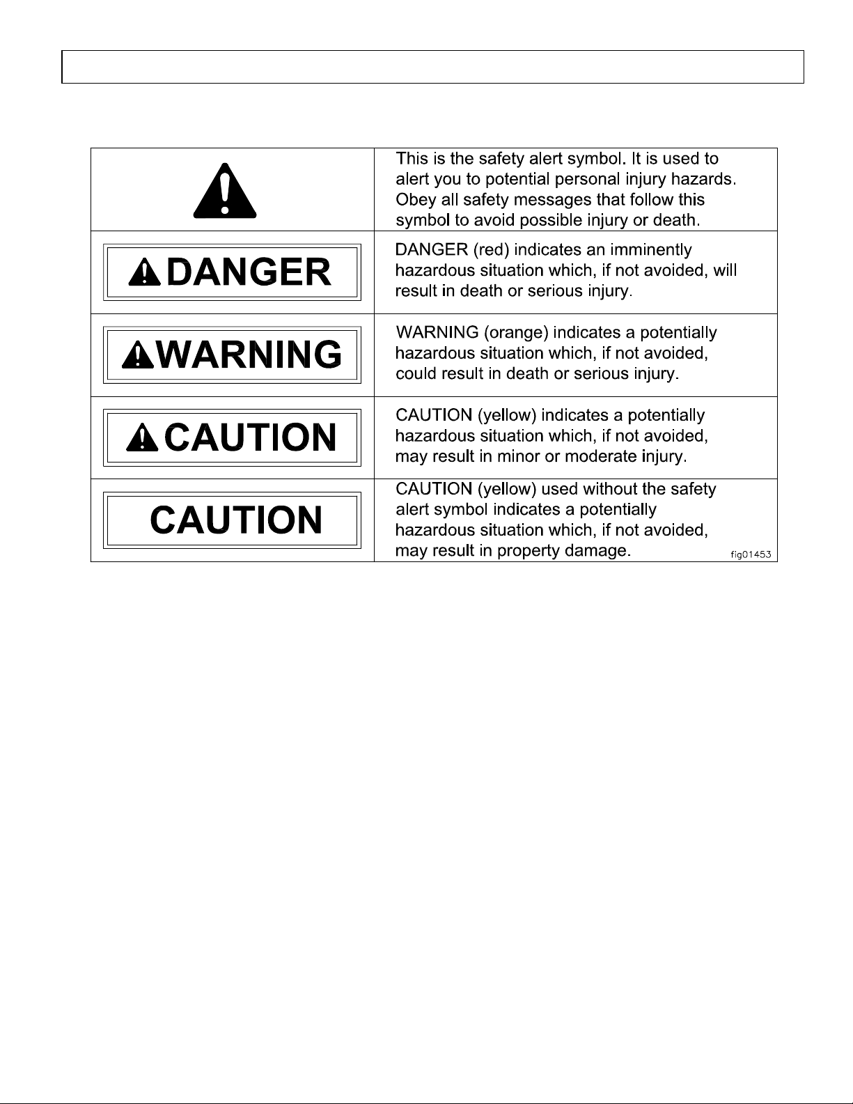
Hazard Signal Word Definitions
2
Page 3

Table of Contents
Hazard Signal Word Definitions ................................................................................................. 2
About Your Generator ................................................................................................................. 4
Specifications ................................................................................................................................. 6
Safety Label Locations .................................................................................................................. 7
Machine Component Identification ............................................................................................. 8
Power Load Planning & Management ........................................................................................ 11
Installation / Initial Set-Up:
1. Unpacking & Delivery Inspection .......................................................................................... 13
2. Planning the Power Load ........................................................................................................ 13
3. Gas Hook-up Installation for Natural Gas or Propane (LPG) – if using ................................ 14
4. Set-up as a PORTABLE or BUILDING BACK-UP Power Source ...................................... 16
5. Selecting a Suitable Site ......................................................................................................... 19
6. Grounding the Generator ........................................................................................................ 21
7. Battery Installation ................................................................................................................. 22
8. Spark Arrester Installation ...................................................................................................... 22
Operation:
1. General Safety Rules for Operation ....................................................................................... 23
2. Preparing for Operation .......................................................................................................... 26
3. Starting the Engine ................................................................................................................. 30
4. Checking Generator Output .................................................................................................... 32
5. Connecting Loads ................................................................................................................... 33
6. Switching Fuels (during operation) ........................................................................................ 34
7. Stopping the Engine ............................................................................................................... 34
8. Storage & Exercise ................................................................................................................. 35
Maintenance & Repair .................................................................................................................. 37
Troubleshooting ............................................................................................................................. 39
Summary of Important Safety Information for Operation ....................................................... 40
Generator Exploded View ............................................................................................................ 45
Wiring Diagram ............................................................................................................................. 47
Fuel Delivery System ..................................................................................................................... 49
Generator Head Exploded View .................................................................................................. 50
Limited Warranty ......................................................................................................................... 51
3
Page 4

About Your Generator
Thank you for purchasing your NorthStar portable generator!
About Your Generator
This engine-driven, portable generator is designed to provide up to 8000 Watts of
electrical power (10,500 watts continuous, 13,000 watts surge). It can supply power:
1. As a portable power source. You can plug appliances directly into the generator’s
electrical outlets.
2. As a back up, standby power source for a building. A licensed electrician can connect
the generator to your building’s electrical system via the installation of an UL-approved
transfer switch. (See the “Installation & Initial Set-up” section of this manual to learn
more about specific requirements and precautions relating to wiring the generator to your
building’s electrical system.)
You must select a generator adequately sized for your power needs. You need to
determine the power needs of all the appliances/tools you wish to power at the same time and
choose a generator rated to provide at least that power level. See the “Power Load Planning &
Management” section of this manual to determine your specific power load requirements and
then compare them to this generator’s rated capacity. You must not overload the generator.
Overloading will cause damage to the generator and attached electrical devices, and may also
result in fire.
You can power this generator with gasoline, natural gas (NG), or propane (LP) gas. The
generator is designed so that it is easy to switch between fuel sources. However, there are
special initial hook-up requirements for natural gas and propane. See the “Specifications”
section of this manual with regard to specific gas flow and pressure requirements. In addition,
note the following:
♦ Natural gas. The standard delivery pressure provided to your building by your utility
company may not match the requirements of your generator.
a) If your standard delivery pressure is higher than allowable for this generator, you
may need to have a pressure-reducing regulator installed. (Note: The regulator
supplied with this generator is NOT a pressure-reducing regulator).
b) If your standard delivery pressure is lower than allowable for this generator, you will
need changes to your natural gas service to elevate the delivery pressure.
ALL natural gas hook-ups must be completed by trained personnel from your natural gas
utility company and inspected as required by your local building code.
♦ Propane (LP). You will need a minimum 100 lb. LPG gas tank to run this generator – the
vaporization rate is insufficient with smaller tank sizes. A qualified propane gas
technician must set up the valve and hose connection between the propane tank and
generator in accordance with all local regulations and electric code.
See the “Installation / Initial Set-Up: Step 3” section of this manual for more detailed
information.
Be sure to read about site selection and grounding requirements for running this
generator. More detailed information can be found in the “Installation & Initial Set-up, Steps
5 & 6” of this manual.
4
Page 5
About Your Generator (cont’d)
This generator is too heavy for one person to lift without mechanical assistance. An
optional wheel kit is available from NorthStar and is recommended if you will be moving the
generator unassisted. Other optional accessories available from NorthStar include a vinyl
cover for storage, UL-approved transfer switches, and extension cords.
Contact NorthStar Product Support at 1-800-270-0810
with questions about optional accessories or to order.
Read this Manual
Improper use or maintenance of this generator can result in serious injury or death from
carbon monoxide poisoning, electric shock/electrocution, fire/explosion, or burns.
Read this manual completely before using the generator and follow all instructions and
safety rules.
You must follow all instructions and safety precautions presented throughout this manual. A
summary of important safety information can be found at the end of the manual. Keep this
manual for reference and review.
Proper preparation, operation, and maintenance will result in operator safety, as well as best
performance and long life of the generator. For detailed engine operation and maintenance
information, always refer to the engine Owner’s Manual furnished with the generator.
NorthStar is constantly improving its products. The specifications outlined herein are subject
to change without prior notice or obligation. The purchaser and/or user shall assume liability
for any modification and/or alterations of this equipment from original design and
manufacture.
Before using, the user shall determine the suitability of this product for its intended use and
assumes liability therein.
Contact NorthStar Product Support at 1-800-270-0810 for any questions about the
appropriate use of this generator.
WARNING
Warranty Registration
Please fill out and submit the warranty registration card so that we have your contact
information for any future product literature or replacement parts you may need.
ATTENTION:
All Rental Companies and Private Owners who loan this
equipment to others!
All persons to whom you rent/loan this generator must have access to and read this manual.
Keep this owner’s manual with the generator at all times and advise all persons who will
operate the machine to read it. You must also provide personal instruction on how to safely
operate the generator and remain available to answer any questions a renter/borrower might
have.
5
Page 6
Specifications
SPECIFICATIONS
Item Number #165939
Maximum Output 13500 Watts (W)
Continuous Output:
Gasoline
Liquid Petroleum Gas (LPG)
Natural Gas (NG)
Voltage 120 / 240 Volt (V)
Phase Single phase (4-wire)
Frequency Regulation 56.5 - 63.3 Hertz (Hz)
Voltage Regulation 218 - 258 V
Power Factor 1.0 p.f.
Engine 20 HP Honda
Engine Speed 3390 - 3798 RPM
Fuel Type Unleaded gasoline/LPG/NG
Pressure Range (LPG, NG) 7-11” Water Column, 4-6 oz.
Min. Flow Range (LPG, NG) 2.2 Gal/Hr (LPG), 3.25 CFM (NG)
Fuel Capacity 10.0 Gallons (38.0 L)
Oil Capacity See Honda Manual
Starting Method Electric
120V Receptacle 20 Amp (A) duplex (NEMA 5-20R)
120/240V Receptacle 30 Amp (A) locking device
50 Amp (A) straight blade (NEMA 14-50R)
Circuit Breaker (1) 50 Amp (A) thermal magnetic
(1) 30 Amp (A) thermal magnetic
(1) 30 Amp (A) thermal, push to reset
(2) 30 Amp (A) thermal, push to reset
Battery (not included) 12 Volt, 400 CCA minimum,
Dimensions
Length 35.75” (90.8 cm)
Width 24.25” (61.6 cm)
Height 26.25” (66.7 cm)
Dry Weight 340 lb. (155 kg)
Gross Weight 410 lb. (186 kg)
10500 Watts (W)
9600 Watts (W)
8400 Watts (W)
30 Amp (A) locking device
(NEMA L5-30R)
(NEMA L14-30R)
Group size U1
6
Page 7
Safety Label Locations
BATTERIES:
1) contain caustic acid, 2) em it e xplosive gases, 3) can cause electric shock
ALWAYS use eye protection. Caustic acid and ex plosive gas es can cause blindness or severe burns.
NO smoking, sparks, or flames.
NEVER touch both battery terminals at the same time with your hand or any non-insulated tools.
FLUSH immediately with w at er if ba ttery acid c ontacts eyes, skin, or clothing.
CONNECT c ables in correct se quence: FIRST RED to POS ITIVE terminal, th e n BLACK to NEG A TIVE
terminal. When disconnecting, DISCONNECT BLA CK cable first, then RED.
NEVER charge a visibly damaged or frozen battery. ALWAYS read and follow charger instructions.
IF GENERATO R IS TO BE STORED LONGER THA N 2 M ONTHS,
charge battery with a trickle charger that is rated for 3 amps maximum.
©2007 NT+E 1-800-270-0810
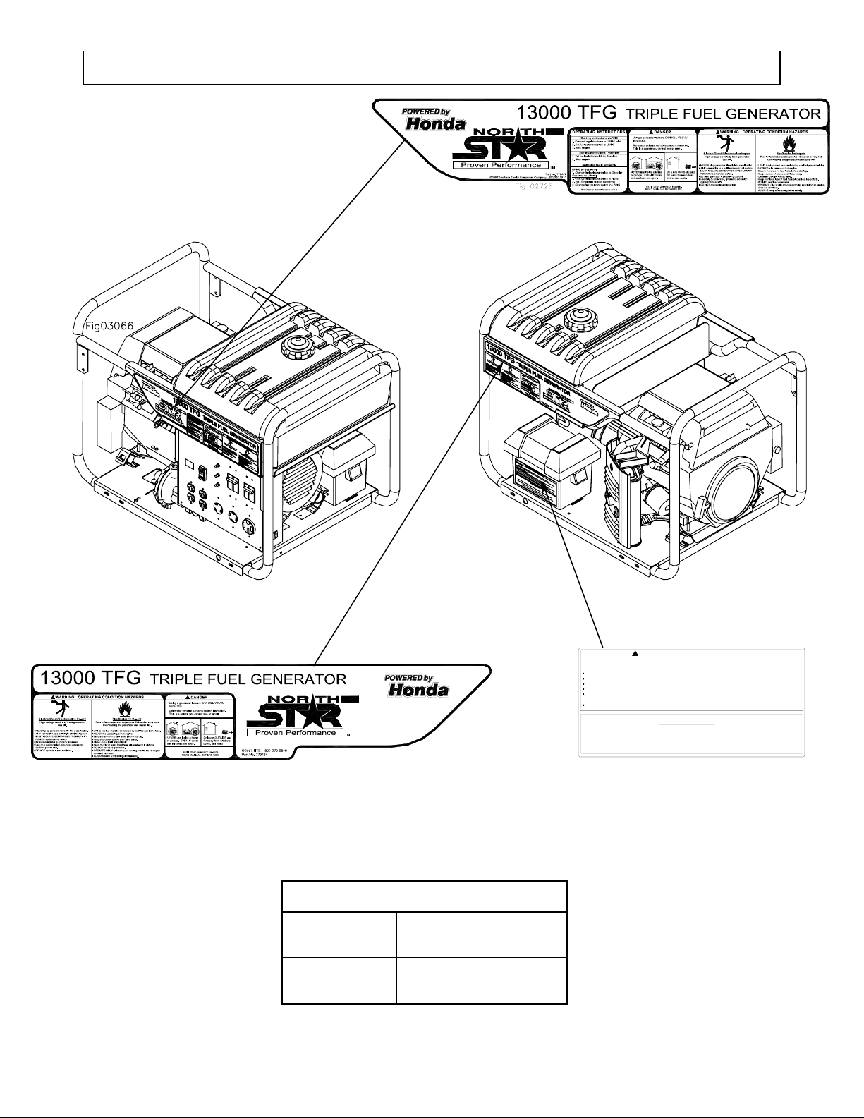
Always make sure safety labels are in place and in good condition. If a safety label is
missing or not legible, order new labels or unsafe operation could result.
To order replacement safety labels, call NorthStar Product Support at 1-800-270-0810.
WARNING - BATTERY HAZARDS
ATTENTION
A charged battery ensures reliable engine starting.
PN 779396
On-Product Warning Labels
Part numbers Description
779396 Battery Warning
779427 Warning 1
779464 Warning 2
7
Page 8

Machine Component Identification - Item #165939M.2
Figure 1 (Ref. 1-19)
Ref. Description Ref. Description
1 Air Cleaner 15 Hour Meter
2 Gas Cap with Gauge 16 Oil Drain Area
3 10.0 Gallon Gas Tank 17 Demand Regulator Assembly
4 Battery Box 18 Engine Oil Drain Plug
5 LPG/NG-3/4” NPT Gas Inlet 19 Oil Level Dip Stick
6 120/240V, 50A, Circuit Breaker 20 Engine Oil Fill Port
7 120/240V, 50A Receptacle 21 Engine Key Switch
8 120/240V, 30A Receptacle 22 Engine Choke Lever
9 120/240V, 30A, Circuit Breaker 23 Vibration Isolation Mount
10 120V, 30A Receptacle 24 Engine Oil Filter
11 120V, 30A Circuit Breaker 25 Muffler
12 120V, 20A Circuit Breaker 26 Generator Head
13 120V, 20A, Duplex Receptacle 27 Gas Line Shutoff Valve
14 Fuel Selector Switch
Figure 2 (Ref. 20-27)
8
Page 9

Machine Component Identification - Item #165939M.2
REFERENCE GUIDE
Reference 1 – Air Cleaner
Reference 2 – Gas Cap with Gauge
Reference 3 – 10.0 Gallon Gas Tank Large tank allows for extended run capabilities. Always allow
Reference 4 – Battery Box
Reference 5 - LPG/NG-3/4” NPT Gas
Inlet
Reference 6 - 120/240V, 50A, Circuit
Breaker
Reference 7 - 120/240V, 50A
Receptacle
Reference 8 - 120/240V, 30A
Receptacle
Reference 9 - 120/240V, 30A, Circuit
Breaker
Reference 10 - 120V, 30A Receptacle
Reference 11 - 120V, 30A Circuit
Breaker
Reference 12 - 120V, 20A Circuit
Breaker
Refer to your Honda engine manual for air cleaner care.
The gas cap is extra large, creating a large hole for refueling
and a comfortable grip. You can always monitor the fu el level
without removing the cap by using the fuel level indicator built
into the gas cap.
room for gasoline expansion by not filling the gas tank
completely full.
The battery box provides protection for the battery and will accept
the standard lawn tractor size battery (Group U1-7). The engine
requires a 12 volts battery. See battery section for sizing.
WARNING Hookup must comply with the Federal and Local
jurisdiction of Liquid Petroleum (LP) and Natural Gas (NG).
ALWAYS have a qualified technician complete the LP/NG
hookup. Improper installation can cause injury or death. LP/NG
are lethal and explosive gases. If you smell gas, exit area
immediately, if possible shut off the LP/NG supply. Before you
start engine, smell next to floor for gas, if you do smell gas:
• DO NOT start engine.
• DO NOT light a match.
• DO NOT flip on an electrical switch.
• Exit area immediately and call gas supplier or fire
department.
Minimum flow range required: NG - 3.25 CFM;
LPG - 9.33 LB/hr., or 2.2 GAL/hr.
Pressure Range: 4-6 ounces, OR 7-11 inches of water column.
NEVER over pressurize.
This portable generator has one 120/240 volt, 50 Amp thermal
magnetic 2 pole circuit breaker. This circuit breaker is the main
line circuit breaker and will sever power to the control panel
receptacles when in the off or tripped position. To reset this circuit
breaker, move the circuit breaker handle to the OFF position.
Then move the breaker handle to the ON position. If the circuit
breaker continues to trip, reduce load to the generator. If
nuisance tripping continues one or more electrical loads may be
defective and must be repaired by a qualified electrician.
The generator control panel has one 120/240 volt, 50 amp NEMA
14-50R receptacle. This receptacle is protected by Reference 6.
The mating plug for this receptacle is a NEMA 14-50P. This
receptacle is useful when installing a transfer switch.
The generator control panel has one 120/240 volt, 30 amp
NEMA L14-30R locking device receptacle. This receptacle is
protected by Reference 9. The mating plug for this receptacle is
a NEMA L14-30P.
This generator has one 120/240 volt, 30 Amp thermal magnetic
2 pole circuit breaker. To reset this circuit breaker, move the
circuit breaker handle to the OFF position. Then move the
breaker handle to the ON position.
The control panel has one 120 volt, 30 amp NEMA L5-30R
receptacle. This receptacle is protected by Reference 11. The
mating plug for this receptacle is a NEMA L5-30P.
The generator control panel has a 120-volt, 30 amp thermal
circuit breaker. To reset the circuit breaker, wait 15 seconds
and press the extended button back into the circuit breaker
housing.
The generator control panel has two 120 volt, 20 amp thermal
circuit breakers. To reset the circuit breaker, wait 15 seconds
9
Page 10
Machine Component Identification - Item #165939M.2
and press the extended button back into the circuit breaker
housing.
Reference 13 - 120V, 20A, Duplex
Receptacle
Reference 14 - Fuel Selector Switch Switching from LP or NG to gasoline:
Reference 15 – Hour Meter
Reference 16 – Oil Drain Area
Reference 17 – Demand Regulator
Assembly
Reference 18 – Oil Drain Plug
Reference 19 – Oil Level Dip Stick
Reference 20 – Engine Oil Fill Port
Reference 21 – Engine Key Switch
Reference 22 – Engine Choke Lever
Reference 23 – Vibration Isolation
Mount
Reference 24 – Engine Oil Filter Replace the oil filter at each oil change. Replace with Honda
Reference 25 – Muffler
Reference 26 – Generator Head
Reference 27 – Gas Line Shutoff
Valve
The generator has a control panel with two duplex (two
receptacles in a common housing) receptacles. This duplex is a
120-volt (V) 20 amp (A) straight blade receptacle, National
Electrical Manufacturer’s Association (NEMA) number 5-20R.
This receptacle accepts NEMA plug number 5-20P. The
duplex is capable of drawing 20A out of either receptacle or a
combination of both.
1. Disconnect all loads to generator.
2. Turn the gas line valve to ON position.
3. Flip the fuel selection switch to the GASOLINE position.
Switching from gasoline to LP or NG:
1. Disconnect all loads to generator.
2. Make sure LP or NG fuel is being supplied.
3. Flip the fuel selection switch to the LP/NG position.
4. Momentary sputtering is common.
5. Turn gasoline line valve to OFF position.
The control panel includes an hour meter to monitor engine run
time. The hour meter will not work if the 120 volt, 20 amp circuit
breaker is OFF (Reference 12).
This product was designed with a large window in the base
directly below the engine oil drain plug (Reference 18). The
large window facilitates a quick and clean process to change
engine oil.
Controls the flow of LP or NG gas into the engine carburetor.
Refer to your Honda engine manual for oil change
recommendations.
Refer to your Honda engine manual for proper oil level
recommendations.
Remove the oil fill cap to add engine oil.
The engine key switch is located on the front of the engine.
Always locate this switch and be familiar with its location before
operating the generator.
Used during cold starts. Refer to the Honda engine manual for
usage.
The engine and generator head is mounted on rubber cylinders
that absorb most of the engine vibration. This feature
eliminates the tendency of the machine to “walk” which is
common with engine-powered equipment.
genuine replacement parts.
This generator is equipped with a quiet style muffler. The
muffler is designed to allow moisture (condensation) to drain
from the bottom of the canister. Always check for loose
fasteners. Included spark arrestor is shipped loose. See Spark
Arrestor Installation section of this manual for information.
The electricity producing part of the generator.
The fuel tank has an ON-OFF valve mounted underneath.
Always keep this valve closed (OFF) when the generator is not
in use.
10
Page 11
Power Load Planning & Management
NEVER exceed the rated wattage capacity of your generator.
WARNING
OVERLOADING may cause SERIOUS DAMAGE to the generator and
attached electrical devices, and may result in fire.
Your generator MUST BE SIZED PROPERLY to provide both the running and starting (surge)
wattage of the devices you will be powering. Before using your generator, determine the running
and starting wattage requirements of all the electrical devices you will be powering simultaneously.
The sum of the running and starting wattages of the devices being powered must not exceed the
continuous output rating of your generator. (The continuous output rating of your generator is listed
in the “Specifications” section of this manual.) Note that:
• Devices without electric motors such as light bulbs, radios, and televisions have the same
running and starting wattage.
• Devices with electric motors such as refrigerators, compressors, and hand tools typically
require a starting wattage that is 3 to 5 times greater than the running wattage.
The running and starting wattage requirements are often listed on a device’s nameplate. If wattage
is not given on the device’s nameplate, the wattage may be calculated by multiplying the nameplate
voltage by nameplate amperage, Watts = Volts X Amps.
Example conversion to watts:
120 Volts X 5 Amps = 600 Watts
If only the running voltage is given on the nameplate for a device with an electric motor, the starting
wattage can be approximated to be three to five times the running wattage.
Estimates for the running wattage requirements for common devices are listed in Table 1 below.
Guidance for starting wattages is provided in the table’s footnotes.
Table 1
Device
Air conditioner (12.000 BTU) 1700 (a,b) Jet pump 800 (a)
Battery charger (20 Amp) 500 Lawn mower 1200
Belt sander (3”) 1000 Light bulb (100 Watt) 100
Chain saw 1200 Microwave oven 700
Circular saw (6½”) 2000 (a,b) Milk cooler 1100 (a)
Coffee maker 1800 (a,b) Oil burner on furnace 300
Compressor (1 HP) 1400 (a,b) Oil-fired space heater (140,000 Btu) 400
Compressor (3/4 HP) 1800 (a) Oil-fired space heater (85,000 Btu) 225
Compressor (1/2 HP) 1400 (a) Oil-fired space heater (30,000 Btu) 150
Curling iron 700 Oven 4500
Dishwasher 1200 Paint sprayer, Airless (1/3 HP) 600 (a)
Edge trimmer 500 Paint sprayer, Airless (handheld) 150
Electric nail gun 1200 Radio 200
Electric range (1 element) 1500 Refrigerator 600 (b)
Electric skillet 1250 Slow cooker 200
Running
Watts Device
Running
Watts
11
Page 12
Power Load Planning & Management (cont’d)
Device
Furnace fan (1/3 HP) 1200 (a) Submersible pump (1-1/2 HP) 2800 (a)
Freezer 800 (b) Submersible pump (1 HP) 2000 (a)
Hair dryer 1200 Submersible pump (1/2 HP) 1500 (a)
Hand drill (1”) 1100 Sump pump 600 (a)
Hand drill (1/2”) 875 Table saw 2000 (a)
Hand drill (3/8”) 500 Television 500
Hand drill (1/4”) 250 Toaster 1000
Hedge trimmer 450 Vacuum cleaner 250
Home computer 150 VCR 70
Impact wrench 500 Water Heater 3000
Weed trimmer 500
Running
Watts Device
Running
Watts
(a) Hard-starting motors require 3-5 times the rated running watts
(b) For extremely hard to start loads such as air conditioners and air compressors, consult the
equipment dealer to determine maximum wattage
To calculate the running and starting wattage requirements for the devices you will be
powering, follow these steps:
1. Make a list of all electrical devices you will be powering at the same time with the generator.
2. List the greater of the running or starting wattage next to each device as obtained from the
devices’ nameplate or Table 1. If only the running wattage for a device with an electric
motor is known, the starting wattage can be estimated to be at least 3 times the running
wattage.
3. Add the wattages for all devices on your list. This total must be lower than the continuous
output rating of your generator.
Example:
Device to be Powered
Starting/Running Wattage
Greater of
Light Bulb 75 W
Refrigerator – 18 Cu. Ft. 1600 W
Microwave 700 W
Window AC 1800 W
Sump pump (1/3 hp) 2100 W
Total 6275W
In this example, the generator must have a continuous output of at least 6275 W in order to
power all of the devices simultaneously.
STAGGERING LOADS
You can increase the number of devices your generator can power by staggering the load on the
generator. For example, you could alternately power your refrigerator and air conditioner for
limited periods of time -- powering only one of the devices at a time and never powering both at the
same time.
12
Page 13

Installation / Initial Set-Up
There are a number of important steps required to set up your generator for initial use. These
steps are:
Steps for Installation / Initial Set-Up
1. Unpacking & delivery inspection.
2. Planning the power load to stay within the generator’s rated
capacity.
3. Getting gas hook-ups installed if natural gas or LP gas will be used as
a fuel source.
4. Setting up generator for the type of power generation you need:
a. portable power source, or
b. connected to a building as a back-up power source.
5. Selecting a site for using the generator.
6. Grounding.
7. Battery installation (electric start models only).
Each of these steps is discussed in detail below:
1. Unpacking & Delivery Inspection
You should inspect the generator immediately after you receive delivery.
See the “Machine Component Identification” section of this manual for a
• If you have missing components, contact Product Support at 1-800-270-0810.
• If you have damaged components, contact the freight company that delivered the unit and file a
Plan your power load so that you do not exceed the generator’s rated capacity.
See the “Power Load Planning & Management” section of this manual to review how to plan and
manage power loads for the generator.
diagram of the generator and its components.
claim.
2. Planning the Power Load
13
Page 14
Installation / Initial Set-Up
3. Gas Hook-up Installation for Natural Gas or LPG (if needed)
You can power this generator with gasoline, natural gas (NG), or propane (LP) gas. The generator
is designed so that it is easy to switch between fuel sources. However, there are special initial
hook-up requirements for natural gas and propane:
WARNING:
If you choose to operate the generator on NG or LPG, you must have the fuel line system
installed by a certified gas technician.
Specific requirements for each type of hook-up are given below:
Natural Gas (NG)
Hook-up
Contact your gas utility company for installation of a natural gas hookup for the generator.
WARNING:
Natural gas is a highly explosive gas. All natural gas hook-ups must
be completed by trained personnel from your natural gas utility
company and inspected as required by your local building code.
♦ This product is designed to operate on NG at a gas pressure range of 4 to
6 ounces per square inch (7”-11” of water column) and requires a
minimum NG flow rate of 3.25 CFM.
♦ The standard gas pressure normally delivered to your building by your
utility company may be higher or lower than the required 4-6 ounces per
square inch (7”-11” of water column):
o If your standard delivery pressure exceeds 4-6 ounces per square
inch (7”-11” water column), you will need a pressure-reducing
regulator installed. Excessive gas pressure will permanently
damage this product and void the warranty if the generator is not
installed correctly with a pressure-reducing regulator as needed.
Note: The regulator supplied with this product is NOT a
o If your standard delivery pressure is lower than 4-6 ounces per
square inch (7”-11” water column), you will need changes to your
natural gas service to provide elevated delivery pressure. In
addition you will need to have a pressure-reducing devices installed
for your other natural gas appliances.
Propane (LPG)
Hook-up
Contact your local propane supplier to install a propane fuel system for
the generator.
WARNING:
LPG is a highly explosive gas. A qualified propane technician
must make the valve and hose connection between the propane
tank and generator in accordance with all local regulations and
electrical codes. All LPG hook-ups should be completed by
trained personnel from propane supplier and inspected as
required by your local building code.
pressure-reducing regulator, but one can be supplied
and installed by your gas utility technician at the time
of fuel system hook-up.
14
Page 15

Installation / Initial Set-Up
♦ This product is designed to operate at an LPG gas pressure range of 7” to
11” of water column and requires a minimum LPG gas flow rate of 9.33
lb/hr, 2.2 Gal/hr, or 201,718 BTU/hr.
Note: All gas cylinders produce gas pressure in excess of 11” water
column. Introduction of gas pressure into the generator in
excess of 11” water column will permanently damage this
product and void the warranty. You will need a pressure-
♦ You will need a minimum 100 lb. LPG gas tank to operate the generator.
This generator will not work with 20-lb gas cylinders used in gas grills
and recreational equipment, or 40-lb gas cylinders used in forklifts and
tractors. These smaller gas tanks do not have a sufficient vaporization
rate to run the generator.
Some installations may require tanks even larger than 100-lb as a result
of low surrounding air temperature and other appliances drawing fuel
from the same tank.
reducing regulator installed as part of your LP gas fuel system.
15
Page 16

Installation / Initial Set-Up
4. Set-up either as a BUILDING BACK-UP or PORTABLE Power Source
This generator is designed to provide up to 13,000W of electrical power. It can supply electricity in
two ways:
1. As a back up, standby power source for a building. For this application, you must arrange
for a licensed electrician to connect the generator to your building’s electrical system via the
installation of an UL-approved transfer switch. The transfer switch must be installed in
accordance with building electrical code and guidelines supplied by your power company.
2. As a portable power source. You can plug appliances or tools directly into the generator’s
electrical outlets.
Specific requirements for each are given below.
Note: Regardless of whether you use your generator as a back-up power source connected to a
building or as a portable power source, you must not overload the generator. Overloading
may cause serious damage to the generator and attached electrical devices.
Using as a
Back-up Power
Source for a
Building
Contact a licensed electrician to install an UL-approved transfer switch if
you want to use your generator as a back-up power source for a building.
What does a transfer switch do? It:
a) Safely connects the generator to your building’s electrical system by
isolating your generator from your utility company’s power lines,
AND
b) Connects your generator to a critical subset of your building’s circuits
that are needed for emergency power needs.
If your generator will be connected to your building’s electrical system, it
MUST ALWAYS be isolated from the utility power grid with a UL-approved
transfer switch installed by a licensed electrician in compliance with all
applicable building and electrical codes, and in accordance with guidelines
supplied by your power company.
DANGER:
A transfer switch must be installed in order to isolate your
generator from the utility power grid. If your generator is NOT
properly isolated from the utility system, serious hazards will
arise:
When your generator is running, it’s output will back feed into
♦
the utility power line and transformer that are normally used to
provide you with power. The transformer will step up the
current to the normal line voltage. An unsuspecting utility line
worker working on what he thinks is a deactivated line could
be electrocuted.
♦ If your generator is connected (running or not) when utility
power is restored, your generator will be destroyed. It could
also explode or cause fire.
In addition to isolating your generator from the utility system, the transfer
switch connects your generator to a limited set of circuits in your building
that have been chosen as critical to operate during a power outage.
16
Page 17

N
N
R
R
Using as a
Portable Power
Source
Installation / Initial Set-Up
The generator cannot power your entire home -- you must work with the
installing electrician to determine which devices/appliances you wish to
power during an outage. The electrician can help you determine which
circuits and devices can be powered simultaneously without overloading the
generator.
(See the previous section of this manual entitled “Power Load Planning &
Management” for more information on load application and selection.)
When using the generator as a portable power source, you can plug
electric devices and appliances directly into the generator’s electrical
outlets.
There are four different kinds of electrical outlets on the generator:
1. One 120/240 Volt, 50 Amp straight-blade receptacle (NEMA 14-50R
receptacle compatible with NEMA 14-50P mating plug)
2. One 120/240 Volt, 30 Amp locking receptacle (NEMA L14-30R
locking receptacle compatible with L14-30P mating plug)
3. One 120 Volt, 30 Amp locking receptacle (NEMA L5-30R receptacle
compatible with NEMA L5-30P mating plug)
4. Two 120 Volt, 20 Amp duplex straight-blade receptacles (NEMA 5-
20R duplex receptacles compatible with NEMA 5-20P or 5-15P
mating plugs).
(2)
NEMA
5-20
Duplex
LP/N
NEMA
L5-30
EMA
L14-30R
(See more technical detail about these receptacles and their associated
circuit breakers in the “Machine Component Identification” section of this
manual.)
♦ Make sure you plug each electrical device/appliance into the correct
generator outlet based on the device’s plug configuration and
voltage/amperage rating. Never exceed the amperage rating of an outlet.
EMA
14-50R
17
Page 18

Installation / Initial Set-Up
♦ Extension cords may be used to power devices that are located at a
distance from the generator. However, use only UL-listed, outdoor-rated,
grounded extension cords of the proper size. Use Table 2 below to choose
an adequately sized extension cord according to the amperage of the
device being used and the length of the cord.
Table 2
♦ All extension and appliance cords must be in good condition and not worn,
Northern Tool is NOT responsible for damage or injury resulting from
customer use of inadequate extension cords.
Current/Power Maximum Extension Cord Length
Amps at
240V
Load
(watts)
#10 Ga.
Cord
#12 Ga.
Cord
#14 Ga.
Cord
#16 Ga.
Cord
10 2400 250' 150' 100' 75'
20 4800 125' 75' 50' 25'
30 7200 60' 35' 25' 10'
40 9600 30' 15' 10' *
50 12000 15' * * *
WARNING:
Use of under sized extension cords can cause electric shock,
fire, or damage to connected devices.
bare, frayed, or otherwise damaged.
WARNING:
Use of damaged electric cords can cause electric shock or fire.
Note: If an extension cord becomes hot to the touch, it is overloaded or
damaged and must be replaced.
18
Page 19

Installation / Initial Set-Up
5. Select a Suitable Site
Before using the generator, you must select a suitable OUTDOOR location for installation and
operation. This location should meet all of the criteria listed below.
WARNING:
You must choose a suitable site for operating your generator to avoid equipment
damage and/or injury and possible death from carbon monoxide poisoning, electric
shock, or fire. Choose a site that meets all of the criteria specified.
Dry, level surface The generator should be positioned on a dry, firm, level surface.
Ensure that the generator sits level and will not slide or shift during operation.
If applicable, block the generator’s wheels to prevent sliding and shifting.
Outdoors only –
dangerous carbon
monoxide exhaust
Adequate cooling
ventilation
WARNING: Carbon monoxide poisoning hazard
The exhaust from your generator contains carbon monoxide (CO), a
poisonous gas that can kill. You cannot smell it, see it, or taste it.
Carbon monoxide exhaust is given off whether you are using gasoline,
natural gas, or propane as the fuel source to power the generator.
Follow the directions below for choosing a location to operate your
generator in order to avoid carbon monoxide poisoning.
The location you choose to operate the generator must be OUTDOORS
and away from all air intakes:
• Never run the generator inside any closed or semi-enclosed spaces (even if
outdoors), including homes, garages, basements, sheds, or boxes. These
spaces can trap poisonous gases, even if you run a fan or open windows.
• Place the generator so that the exhaust fumes will not be directed towards
people or building air intakes.
• Ensure that working, battery-operated or battery back-up carbon monoxide
alarms are used in any dwelling/structure that is in close proximity to the
running generator.
• Note that this generator is NOT designed or approved for use in vehicles
or marine applications. Never run the generator inside RVs or other
vehicles, on boats, or on pick-up truck beds.
WARNING:
Never attempt to attach ductwork to the muffler system to allow
for installation inside an enclosure. This could cause hot air
deflection, heat build-up, and increased exhaust back-pressure,
resulting in possible exhaust leakage or damage to the generator.
The generator needs adequate, unobstructed flow of air to allow for
proper cooling of engine and generator head.
WARNING:
Heat build-up from inadequate ventilation can result in fire, posing a
serious risk to nearby persons and structures.
• Situate so there is adequate clearance around generator to allow for
cooling airflow so that heat does not build up.
19
Page 20

Installation / Initial Set-Up
• Never place the generator immediately adjacent to a building or other
structure – allow at least a 7’ clearance.
• Do not run the generator in close proximity to other heat-generating
equipment, such as another generator. The combined heat that is
generated may raise air temperature in the immediate area and there will
not be adequate cooling ventilation.
• Do not allow debris to accumulate and block airflow.
• Do not operate with a tarp, blanket, or cover surrounding the generator.
No wet conditions Choose a location where the generator will NOT be exposed to rain,
snow, or direct sunlight. Exposure to water can cause electric shock.
You may operate the generator under an outdoor, canopy-like structure of
heat-resistant material that is open on all sides. Make sure that all parts of
canopy are at least 7’ from exhaust, and allow for adequate clearance above
generator so that heat does not build up.
Hot exhaust
clearance
Away from
dust/dirt
Hearing
protection
The exhaust gas from your generator is extremely hot and can cause
combustible materials to catch on fire.
• Make sure your generator’s exhaust system is at least 7 feet from all
combustible materials and buildings/structures.
• Equip the engine with a spark arrestor if the generator will be used near
any ignitable forest, brush, or grassy land. (See the “Specifications”
section of this manual to determine if your generator is already equipped.)
Make sure you comply with applicable local, state, and federal codes.
• Keep a fire extinguisher rated “ABC” nearby. Keep it properly charged
and be familiar with its use.
Do not use the generator in extremely dusty or dirty conditions.
Excessive dust and dirt can cause premature failure of the machine.
Generators can produce noise levels of up to 95 dB in close proximity,
which can be dangerous to human hearing with prolonged exposure.
Hearing protection may be required for persons working within 15-20 feet of
the running generator for an extended period of time.
WARNING:
Never attempt to attach ductwork to the muffler system to lower noise
levels. This could cause hot air deflection, heat build-up, and
increased exhaust backpressure, resulting in possible exhaust leakage
or damage to the generator.
20
Page 21

Installation / Initial Set-Up
t
d
6. Grounding the generator
Always ensure the generator is properly grounded to prevent electrical shock.
You must always ground the generator by the following method when using the generator as a
portable electrical source:
1) Drive a ¾” or 1” copper pipe or rod into the ground close to the generator. The pipe/rod
must penetrate moist earth – the depth required will be dictated by local soil conditions.
Consult with an electrician.
2) Connect an approved ground clamp to the pipe.
3) Run a 10 gauge wire from the clamp to the generator grounding post located on the rear of
the generator head.
4) Do not connect the generator grounding post to a water pipe or a ground used by a radio
system.
10 Ga.
wire
If a licensed electrician installs the generator with a connection to your building’s electrical circuit
for use as a back-up power system, grounding may alternatively be completed through the
building’s grounding system. Ask your electrician. If the generator is not grounded through your
building’s electrical system, follow the procedure above.
Grounding
Pos
Groun
Copper
Pipe/Rod
WARNING:
Operating the generator when it is not properly grounded can result in electrical shock.
21
Page 22

Installation / Initial Set-Up
r
7. Battery Installation
Your generator’s engine is equipped with an electric starter which requires the installation of a 12volt lawn tractor size battery (Group U1). See the “Specifications” section of this manual for more
specific battery requirements for this generator model, such as minimum amperage or CCA rating.
The battery is to be supplied by the customer and should be installed in the protective battery box
located near the engine. Follow the instructions detailed below for connecting and disconnecting
the battery.
WARNING: Battery hazards
Batteries are hazardous because they contain caustic acid, can emit explosive gases, and can
cause electric shock. Caution must be exercised when making connections to a battery to
avoid shock and contact with the acid, and to prevent any sparking that could lead to an
explosion.
ALWAYS follow the general battery safety rules and instructions listed below.
General Battery
Safety Rules
Connecting the
battery
Disconnecting the
battery
Installing the
spark arrestor
• ALWAYS use eye protection when handling batteries.
• NEVER smoke or work near sparks or other sources of ignition.
• NEVER touch both battery terminals at the same time with your hand or
any non-insulated tools.
• If battery acid contacts skin or clothing, flush immediately with water and
neutralize with baking soda.
Always connect the cables in the following sequence to avoid possible shock:
1. Find the battery cables located inside the battery box.
2. Connect the red cable to the positive(+) terminal of the battery.
3. Then connect the black cable to the negative(-) terminal of the battery.
Always disconnect cables in the following sequence to avoid possible shock.
1. First, disconnect the black cable from the negative(-) terminal of the
battery.
2. Next, disconnect the red cable from the positive(+) terminal of the
battery.
8. Spark Arrestor Installation
1. Push spark arrestor into outlet
pipe.
2. Attach the spark arrestor to the
outlet pipe with screw as
shown. (Screw is designed to
drill through the outlet pipe.)
3. Maintenance – Remove
arrestor and clean screen
annually or as required.
Outlet pipe
Arresto
Screw
22
Page 23

Operation
Once you have set up your generator for use, it is time to start your generator. The following
are the procedures necessary for safe, successful operation of your generator.
Operation Procedures
1. General Safety Rules for Operation
2. Preparing for Operation
3. Starting the Engine:
a) Using LP/NG
b) Using Gasoline
4. Checking Generator Output
5. Connecting Electrical Loads (Portable Power Generation)
6. Switching Fuels:
a) From LP/NG to Gasoline
b) From Gasoline to LP/NG
7. Stopping
8. Storage & Exercise of Generator
Each of these procedures is discussed in detail below:
1. General safety rules for operation
Before starting the generator, review the following general safety rules for operation:
• Know proper use/how to stop. Be thoroughly familiar with proper use of the equipment and all
• Instruct operators. The generator owner must instruct all operators in safe generator set-up and
• Intended use. Carefully read about and understand the intended use of this generator. Do not
• Under the influence. Never operate, or let anyone else operate, the generator while under the
• Safety equipment / controls. Do not operate the generator unless all safety covers, guards, and
• Damaged. Do not operate the generator with damaged, missing, or broken parts.
• Modifications. Do not modify the generator in any way. Modifications can create serious
• Engine speed. Never attempt to modify the engine speed setting. The engine speed is preset at
WARNING:
Failure to follow safety rules may result in serious injury or death to the operator or
bystanders.
generator controls, output receptacles, and connections. Know how to stop the generator quickly
if needed (see “Operation, Step 7 - Stopping the Engine”).
operation. Only trained adults should set up and operate the generator – Do not let children
operate.
use for other purposes, as unforeseen hazards or equipment damage may result.
influence of alcohol, drugs, or medication.
barriers are in place and in good working order, and all controls are properly adjusted for safe
operation.
safety hazards and will also void the warranty.
3600 RPM for safe and optimal performance of the generator. If speed needs adjusting, it must
23
Page 24

Operation (cont’d)
be done by factory-authorized personnel.
• External fuel sources. Never attempt to connect external gasoline/diesel sources in order to
increase engine run time. Larger tank at pressure or higher elevation will cause gasoline to leak
from carburetor during operation. Fire or explosion could result.
• Malfunction during operation. Immediately turn off the generator if any of the following
conditions arise during operation:
o Excessive change in engine speed, slow or fast
o Overheating in load connecting devices
o Sparking or arcs from generator
o Loss of electrical output
o Receptacle damage
o Engine misfire
o Excessive vibration
o Flame or smoke
o Abnormal noise
• Adjusting / repairing. Always turn off generator and remove spark plug(s) or spark plug
wire(s) before working on the generator to prevent accidental starting. Always discharge the
capacitor before working on the generator head to prevent electrical shock. (See Maintenance &
Repair section of this manual for instructions on how to do this.)
• Carbon monoxide poisoning. The running engine gives off carbon monoxide, a poisonous gas
that can kill you. You CANNOT smell it, see it, or taste it. Follow all instructions for site
selection and positioning the generator, and avoid inhaling the exhaust. If you start to feel sick,
dizzy, or weak while using the generator, shut off the engine and get to fresh air RIGHT AWAY.
See a doctor. You may have carbon monoxide poisoning.
• Other exhaust dangers. This product contains or emits chemicals known to the State of
California to cause cancer, birth defects or other reproductive harm. Avoid inhalation of
exhaust.
• Wet conditions. Do not operate the generator or handle any electrical equipment while standing
in water, while barefoot, while hands are wet or while in the rain or snow. Electric shock may
result.
• Ground fault circuit interrupter. Always use a ground fault circuit interrupter (GFCI)
protected extension cord (or outlet, if generator is equipped) in damp or highly electrical
conductive areas and on construction jobsites to prevent electrical shock.
• Avoid contact. Avoid contact with bare wires, terminals, connections, etc. while the unit is
running.
• Electric shock accident. If an electric shock accident occurs, immediately shut down the source
of electrical power. If this is not possible, attempt to free the victim from the live conductor.
Avoid direct contact with victim. Use a nonconducting implement, such as a dry rope or board,
to free the victim from the live conductor. Apply first aid and get immediate medical help.
• Smoking/sparks. Never smoke near the running generator, and never operate near sources of
sparks or flames.
• Hot muffler. Never touch hot muffler, hot exhaust manifold, or engine cooling fins. Exhaust
and engine parts can be very hot and will burn you.
• Moving parts. Keep hands, feet, and apparel away from drive belts, fans, and other moving
parts. Never remove any drive belt or fan guard while the unit is operating
24
Page 25

Operation (cont’d)
Static electricity and filling the gasoline tank:
Static electricity can initiate from ungrounded gasoline tanks or containers, from flowing
Static electricity can explosively ignite gasoline vapors that are present during the fueling process,
resulting in serious burns to nearby persons. To avoid static electricity while fueling, certain steps
must be followed before and during the fueling process in order to minimize and safely dissipate
static charge build-up:
• Touch a grounded metal object before starting. Always dissipate static charge from your
body before beginning the fueling process by touching a grounded metal object at a safe
distance away from fuel sources.
• Use a portable container to fill tank. Never fill the generator’s gas tank directly from the
fuel pump – the generator’s tank is not grounded and the high velocity flow of gasoline from a
fuel pump can cause static electric build-up. Use an approved portable container to transfer
gasoline to the generator’s tank.
• Fill container on the ground. Never fill the portable gas container while it is sitting inside a
vehicle, trailer, trunk, or pick-up truck bed. ALWAYS place container on the ground to be
filled.
• Keep nozzle in contact with container. Keep nozzle in contact with the portable container at
all times while filling. Manually control the flow of gasoline; do NOT use the nozzle’s lockopen device.
• Use a portable container made of metal or conductive plastic. It will dissipate charge to
ground more readily.
About static electricity and fueling
Many common objects can accumulate and retain a static electric charge. Objects made of non-conductive
materials (e.g. plastics) easily accumulate and retain static electric charge, as can objects made of conductive
material (e.g. metal, water) if they are not electrically grounded. The static electric charge on an object, such
as a human body or plastic fuel tank/container, can reach as high as several thousand volts!
A static electric spark can be generated if the static electric charge stored on an object “jumps” to another,
less charged object. Such a spark can ignite invisible gasoline vapors that are present during fueling
situations.
Typical sources of static electric hazards during fueling
The following objects can accumulate a static electric charge and cause an ignition spark in typical fueling
situations:
1) Ungrounded tanks/containers. Any ungrounded fuel tank or container can accumulate a static electric
2) Flowing gasoline. Most people are not aware that gasoline accumulates static electric charge while
Persons. A person dispensing the gasoline can carry a static electric charge on their body, typically
3)
charge as a result of contact with other objects or friction during transportation. This static electricity
can discharge as a spark to the grounded gasoline dispenser nozzle, as the nozzle is first brought close to
the tank/container at the beginning of the fueling process.
flowing through a hose or pipe. This charge then transfers to and accumulates in the gas tank or container
that is being filled. The total amount of charge accumulation depends on the amount of gas pumped into
the container, the speed with which it is pumped, and whether or not the tank/container is grounded. If
sufficient static electric charge accumulates in the fuel tank or container during the fueling process, the
tank/container may discharge a spark to the grounded gasoline dispenser nozzle.
resulting from contact with their car seat or electronics. The static electricity can discharge as a spark
between that person’s hand and either the grounded dispenser nozzle or the fuel tank opening.
gasoline, and from persons carrying a static electric charge
25
Page 26

Operation (cont’d)
2. Preparing for Operation
Position
generator
Ground
generator
Perform
scheduled
maintenance as
needed
Check/add oil Check the oil level us ing the dipstick and add oil as needed.
Position generator in accordance with the instructions given in
“Installation & Initial Set-up, Step 5: Select a Suitable Site” of this
manual.
Operate outside only, on dry, level ground with adequate clearance and
ventilation.
WARNING: Carbon monoxide poisoning hazard
Generators give off carbon monoxide exhaust, a poisonous gas that can
kill. You CANNOT smell it, see it, or taste it. ONLY run generator
OUTDOORS and away from air intakes. NEVER run generator inside
any enclosed or semi-enclosed spaces, including homes, garages,
basements, sheds, boxes, pick-up truck beds, RVs, or boats. These spaces
can trap poisonous gases, EVEN if you run a fan or open windows.
Carbon monoxide exhaust is given off whether you are using gasoline,
natural gas, or propane to power the generator.
Make sure the generator is grounded in accordance with instruction given
in “Installation & Initial Set-up, Step 6: Grounding the Generator” of
this manual.
WARNING: Electric shock hazard
Always ensure generator is properly grounded to prevent electrical shock.
Make sure that any regular maintenance has been performed as prescribed
in this manual in the “Maintenance & Repair” section.
1. Refer to the engine owner’s manual for engine maintenance instructions.
2. Make sure battery is charged. Charge as needed according to your
battery manufacturer’s instructions.
Using a funnel, add oil up to the FULL mark on the dip stick with the
recommended oil type for your engine and expected ambient conditions.
(See engine Owner’s Manual for oil type and capacity, and more detailed oil
check/fill instructions.)
WARNING: Burn hazard
Never open oil port while engine is running. Hot oil can spray over face
and body.
Notes:
o Low oil shutdown feature prevents the generator from starting without
sufficient oil.
o Engine is shipped without oil. You must add oil before first use.
IMPORTANT:
Under long, continuous-run operating conditions, be prepared to:
• Check engine oil level every time you refuel the engine if using gasoline,
or every 24 operating hours if using NG/LPG.
• Change oil after the first 20 operating hours, and at least every 100
operating hours thereafter, or as directed in engine owner’s manual.
26
Page 27

Operation (cont’d)
Fill gasoline
tank (if using
gasoline)
Check the gasoline level in the generator’s tank if you will be operating the
generator on gasoline.
If needed, fill tank with fresh unleaded gasoline from a portable container,
after first reading the warnings and instructions below.
WARNING: Gasoline fire/explosion hazard
Gasoline is highly flammable and explosive. Heat, sparks, and flames
can ignite gasoline vapors, which can become widespread during fueling.
A flash fire and/or explosion could result and cause serious injury or
death. Use extreme care when handling gasoline. Carefully follow all
the instructions in this section to avoid the following conditions which
could result in gasoline ignition:
• gas vapor collection inside enclosures
• static electric sparks
• sparks from electric wiring, batteries, or running engines
• sources of heat (such as a hot engine or exhaust)
• open flames, including pilot lights
1) Before starting, review the following general safety precautions for fueling:
a) Never pump gasoline directly into the generator’s gas tank at a gas station –
high velocity flow from the pump could result in a static electric build-up
in the generator’s tank. Always use a portable container to fill the tank.
See warning box about static electric spark hazards below.
b) Fill gasoline tank OUTDOORS – never indoors.
c) Stay away from all sources of heat, sparks, and flames. Do not smoke.
2) Turn generator engine off and allow to cool for at least two minutes before
removing gas cap.
Note: A running or still-hot engine is hot enough to ignite fuel.
3) Remove generator gasoline cap.
4) Add gasoline through the fill opening:
- Use only a UL-approved portable gasoline container to transfer the gasoline
to the generator’s tank. Follow the safety warning and instructions below
for avoiding static electric sparking.
- Do NOT overfill the gasoline tank. Allow at least 1/2” of empty space
below the fill neck to allow for fuel expansion.
WARNING: Static electric spark hazard
A static electric spark can explosively ignite gasoline vapor,
resulting in a flash fire that could cause serious injury or death.
To avoid static electric sparking while filling the gasoline tank, the
following steps must be followed to minimize and safely dissipate
static electric charge build-up before and during the fueling
process:
• Always dissipate static charge from your body before beginning
the fueling process by touching a grounded metal object at a safe
distance from fuel sources.
• Never fill the generator’s gas tank directly from the fuel pump – the
27
Page 28

Start LPG/NG
supply
(if using)
Operation (cont’d)
generator’s tank is not grounded and high velocity flow from the
pump can cause static electricity build-up. Use an approved
portable container to transfer gas to the generator’s tank.
• Never fill the portable gas container while it is sitting inside a
vehicle, trailer, trunk, or pick-up truck bed. ALWAYS place
container on the ground to be filled.
• Keep nozzle in contact with portable container while filling.
Manually control the flow of gasoline; do NOT use nozzle’s
lock-open device.
• A portable container made of metal or conductive plastic is
preferred because it dissipates charge to ground more readily.
5) Clean up gasoline spills /splashes immediately.
• If possible, move the generator away from spilled gasoline on the
ground.
• Wipe up spilled gasoline, and wait 5 minutes for excess gasoline to
evaporate before starting engine.
• Gasoline soaked rags are flammable and should be disposed of properly.
• If gasoline is spilled on your skin or clothes, change clothes and wash
skin immediately.
6) Replace gasoline cap securely before starting engine.
7) Store extra gasoline in a cool, dry place in an UL-approved, tightly sealed
container.
IMPORTANT:
For continuous operation, be prepared to check and refuel the engine on a
regular basis. A tank of gasoline should last about 4 hours under 100%
load, and about 8 hours under 50% load.
Propane (LPG):
1) Make sure the fuel hose is securely connected to the propane tank regulator
on one end, and the ¾” NPT gas inlet on the generator base on the other end.
2) Open the propane tank main valve.
3) Check ¾” NPT gas inlet connection for leaks each time you connect. Use the
leak test method described below.
Natural Gas:
1) Make sure the gas line is securely connected to the ¾” inlet on the generator
base.
2) Open line valve, if gas line is so equipped.
Check ¾” NPT gas inlet connection for leaks each time you connect. Use the
leak test method described below.
28
Page 29

Operation (cont’d)
Inspect Fuel
System / Check
for Leaks
Personal
Protection
Inspect fuel system & check for leaks BEFORE starting generator.
Do not start generator until all needed repairs have been completed.
WARNING: Fuel leak hazard
Gasoline, LP gas (propane) and NG (natural gas) are highly explosive and
fuel leaks can result in fire or explosions. You can be burned and
seriously injured if the fuel system is not properly hooked up or there is a
fuel leak when you start the engine.
1) Inspect the entire fuel system. Look for: Signs of leaks or deterioration,
chafed or spongy fuel hose, loose connections, loose or missing fuel hose
clamps, a damaged gasoline tank, or a defective gasoline shut-off valve.
2) If you are using LPG or NG, check for leaks after opening supply valve:
a) Leak test method. Test for leaks on a regular basis by applying a soap
and water solution over pipes, hoses, and connections. Soap bubbles will
form if there is a leak. Use this method to test after each reconnection to
NG/LPG supply (for example, after moving the generator), and on a
regular basis thereafter. This method will help you detect small leaks.
b) Also beware of gas odor. Both LP and NG have an odorant added (rotten
egg/sulfur smell) that will aid in the detection of more dangerous
quantities of leaking gas. Note:
• Natural gas. Natural gas is lighter than air and tends to collect in high
areas.
• LP gas (propane). LP gas is heavier than air and tends to settle in low
areas. Smell next to floor for gas.
If you smell gas, DO NOT start engine! DO NOT light a match. DO NOT flip
on an electrical switch. If possible, shut off LPG or NG supply. Exit area
immediately and call gas supplier or fire department.
1) Hearing can be damaged from prolonged, close-range exposure to the type of
noise produced by this generator. The use of ear plugs or other hearing
protection device is recommended for persons working within 15-20 feet of
the running generator for an extended period of time.
2) Loose or dangling apparel can become entangled in moving parts. Metal
jewelry can conduct electricity. Never wear jewelry or loose-fitting
clothing when starting or operating the generator.
29
Page 30

Operation (cont’d)
A
t
w
3. Starting the Engine
After you have completed the pre-start checklist procedures, you are ready to start the engine.
The following directions detail how to start the engine with either LP/NG or Gasoline as the fuel
source:
Using LP/NG To start engine using LP or Natural Gas:
WARNING:
DO NOT start engine if you smell gas. Exit area immediately
and call gas supplier or fire department. If possible, shut off
gas supply.
1) Disconnect all loads to the generator.
2) Flip fuel selector switch to the LP/NG position.
3) Start the engine:
a) Turn the engine key switch to the START position and hold it there
until the engine starts.
b) When the engine starts, release the key, allowing it to return to the
ON position.
4) It may be necessary to momentarily depress the primer button while
starting the engine, especially for cold starts.
NOTE: If you have trouble starting the engine with LP/NG, you may
need to adjust the load block:
a. Loosen the lock nut, then turn the adjustment screw clockwise
until resistance is felt. At this point the load block is
completely shut-off.
djustmen
Scre
Lock Nut
b. While LP or NG is being supplied to the generator, turn the
ignition key to the start position and slowly turn the adjustment
screw counterclockwise until the engine starts. (Depress the
primer button when cold starting the engine.)
c. Once the engine is running, turn the adjustment screw very
slowly to smooth out engine performance.
d. Once the proper setting is achieved turn the brass lock nut to
secure the adjustment screw.
30
Page 31

Operation (cont’d)
5) Under long, continuous-run operating conditions, be prepared to:
a) Check engine oil level every 24 operating hours,
b) Change oil after the first 20 operating hours, and at least every 100
Using Gasoline To start engine using gasoline:
1) Disconnect all loads to the generator.
2) Flip the fuel selector switch to the GASOLINE position.
3) Turn the gasoline line valve to the ON position.
4) For cold engine, move choke lever to full choke position. To restart a
5) Start the engine:
6) When engine starts, move choke lever to RUN position.
7) Under long, continuous-run operating conditions, be prepared to:
operating hours thereafter, as directed in the engine owner’s manual.
WARNING:
Never open oil port while engine is running. Hot oil can spray
over face and body.
warm engine, move choke lever to half choke or to RUN position.
a) Turn the engine key switch to the START position and hold it there
until the engine starts.
NOTE: If the engine fails to start after 5 seconds, release key and
wait 10 seconds before attempting to start again. Cranking
the electric starter for more than 5 seconds continuously
can overheat and damage the starter motor.
b) Release the key when the engine starts.
a) Check and refuel the engine on a regular basis. A tank of gas should
last about 4 hours under 100% load, and about 8 hours under 50%
load. See engine owner’s manual for more detail.
WARNING:
A running engine is hot enough to ignite fuel. Never add
fuel or remove gas cap if engine is running or still hot.
Let cool at least 2 minutes.
b) Check engine oil level each time you refuel.
c) Change oil after the first 20 operating hours, and at least every 100
operating hours thereafter, as directed in the engine owner’s manual.
WARNING:
Never open oil port while engine is running. Hot oil can
spray over face and body.
31
Page 32

Operation (cont’d)
4. Checking Generator Output
Although the speed of the engine was carefully adjusted at the factory so that the generator
produces the proper voltage and frequency, output voltage should be checked periodically to
ensure the generator is working properly before connecting loads to the generator.
Output voltage should be checked with a portable voltage meter:
1. Start engine and allow to warm up for five minutes. Do not connect any loads.
2. Use voltage meter to check output voltage
at the generator’s outlets/receptacles.
3. Measured voltage should be within the
following ranges:
4. If measured voltage is not within the specified range, have generator adjusted by factory
authorized personnel. Do not attempt to adjust the engine speed yourself.
WARNING:
The generator must be run at the correct speed in order to produce the
proper electrical voltage and frequency. Failure to do so could result
in damage to equipment powered by the generator and possible injury
to the individual.
a. 120V +/- 10% at 120V receptacles.
b. 240V +/- 10% at 240V receptacles.
NOTE:
Slight variation in
voltage/speed with
changing electrical
loads
All engines have a tendency to slow down when a load is applied. When
electrical loads are connected to the generator, the engine is more heavily
loaded and as a result the speed drops slightly.
This slight decrease in speed, together with the voltage drop within the
generator itself, results in a slightly lower voltage when the generator is
loaded to its full capacity than when it is running with no load.
Additionally, there may be small brief surges and drops in voltage as motors
connected to the generator cycle on or off.
The slight variation has no appreciable effect in the operation of motors,
lights, and most appliances.
32
Page 33

Operation (cont’d)
5. Connecting Loads
You will want to be careful when connecting loads so as not to overload the generator, especially if
you are powering devices with motors that require a higher starting power load.
Instructions are provided below for connecting loads when you are using the generator:
o As a portable power source
o Connected to a building as a back-up power source
Using as a
Portable Power
Source
Using as a
Back-up Power
Source for a
Building
WARNING:
Do not overload generator. Make sure that combined starting and running
loads do not exceed rated capacity of generator. Overloading the generator
can cause damage to the generator and attached electrical devices, and may
result in fire.
Connect electrical loads one at a time according to the following
instructions:
1. Allow engine to reach operating speed by allowing it to warm up for
approximately 5 minutes before connecting electrical devices.
2. After engine is warmed up, begin by connecting the items that require
the highest wattage first. The recommended sequence is as follows:
a. Connect items with motors such as refrigerators, freezers, air
conditioners, or small hand tools, one at a time. Let each motor
stabilize before connecting the next device.
b. Connect any lights you are planning on powering.
c. Connect voltage sensitive equipment such as electronics via surge
protectors. Plug devices such as TV’s, computers, and microwaves
into a UL listed voltage surge protector, then plug the surge
protector into the generator.
Each transfer switch installation will be unique.
Proper instructions for how to safely bring the generator online with the
building’s electrical system should be provided by the installing electrician,
who should also provide personal instruction to the owner/operator.
Failure to follow the proper procedure as provided by the electrician could
expose persons to the hazards noted above.
33
Page 34

Operation (cont’d)
6. Switching Fuels (during operation)
You can switch fuel sources (from gasoline to LP/NG, or from LP/NG to gasoline) while the
generator is running. Follow the instructions below:
Switching from
LP/NG to Gasoline
1. Disconnect all loads to the generator. Leave the engine running.
2. Turn the gasoline line shut-off valve to ON position.
3. Flip the fuel selector switch to the GASOLINE position.
Switching from
Gasoline to LP/NG
1. Disconnect all loads to the generator. Leave the engine running.
2. Make sure LP or NG fuel is properly connected to ¾” NPT supply
inlet and is being supplied.
WARNING:
If you smell gas, turn off engine and shut off gas
supply immediately. Exit area and call gas supplier
or fire department.
3. Flip the fuel selector switch to the NONE position. The fuel
conversion should take 1-2 seconds.
4. Wait for the engine to begin sputtering. This indicates the engine is
being starved of gasoline.
5. Flip the fuel selector switch to the LP/NG position.
6. Turn the gasoline line shut shut-off valve to OFF position.
Stop the engine using the following steps:
1. Disconnect all loads to the generator.
7. Stopping
2. Turn engine key switch to OFF position.
3. Turn gasoline line shut-off valve to OFF position.
4. The fuel lock-off solenoid automatically stops the flow of LP or NG to the engine.
5. Remove key from starter to prevent accidental starting of engine.
34
Page 35

Operation (cont’d)
8. Storage & Exercise
When you are finished using the generator, you must:
o Disconnect all loads
o Shut off fuel supply
o Store the generator properly
o Plan on exercising the engine regularly unless the generator is prepared for long-term
storage.
Detailed instructions are provided below.
Disconnect loads &
turn off fuel supply
Cool engine before
storing
Choose a storage
location
Prevent accidental
starting
Exercise generator
every 4 weeks
Perform regular
maintenance
When you are finished using the generator, disconnect all loads and
turn off all sources of fuel supply:
1. Make sure all devices that were connected to the generator’s outlets
are disconnected.
2. Check to be sure gasoline line shut-off valve is in OFF position.
3. If using propane, shut off propane tank valve.
4. If applicable, shut off natural gas line valve.
Let engine cool for at least five minutes before storing. A hot engine can
be a fire hazard.
Store the generator in a location that is:
o Clean and dry
o Away from sources of heat, open flames, sparks, or pilot lights, even
if the generator’s fuel tank is empty. Residual fuel in the tank could
ignite.
o Away from extreme high or low temperatures.
Note: Do not store with battery charger always connected. Batteries that
are over-charged can boil themselves dry and produce excessive amounts of
hydrogen, an explosive gas.
Remove key from starter (for electric start engines) and secure key in a
safe location, or remove spark plug(s) in order to ensure the generator
cannot be started accidentally in a storage location or by untrained persons.
The generator should be exercised regularly.
At least every four weeks, start the engine and let it run for 10 to 15 minutes
with a small load plugged in, such as a lamp or fan.
Monthly exercising of the generator will:
o Dry out any moisture that has accumulated in the windings. If left,
this moisture can cause corrosion in the winding.
o Ensure that the unit is operating properly should it be needed in an
emergency.
Perform periodic maintenance as directed in this manual to keep the
generator in safe working condition.
35
Page 36

Operation (cont’d)
Prepare engine for
long term storage if
needed
If you will not be able to exercise the generator regularly, you must
prepare the engine for long term storage to prevent gum deposits from
forming and causing malfunction of the engine.
Prepare engine for long term storage by:
o Removing all gasoline from the tank and carburetor
OR
o Adding fuel stabilizer to the gasoline (following manufacturer’s
instructions)
Fuel stabilizer steps:
1. Ensure gasoline tank is full.
2. Add fuel stabilizer to fuel tank.
3. Run engine at least 10 minutes after adding stabilizer to
allow it to enter the fuel system.
4. Shut off engine
5. Disconnect spark plug wire and remove spark plug
6. Add one teaspoon oil through spark plug hole
7. Place rag over spark plug hole and turn starter (or pull the
recoil) a few times to lubricate the combustion chamber.
8. Replace spark plug, but do not reconnect the spark plug wire.
36
Page 37

Maintenance & Repair
Inspect and maintain your generator as specified below in order to keep it in safe and optimal
working order. Follow all safety rules and recommended maintenance steps.
ALWAYS shut off the engine, disconnect the spark plug(s) and discharge the capacitor
before cleaning, adjusting, or servicing the generator. Make sure all guards and shields are
replaced before using.
Note: The generator head is brushless and maintenance free. The bearing is a heavy-duty
sealed ball bearing, which requires no maintenance or lubrication.
Maintenance & Repair
Follow safety rules Read and follow these safety rules whenever you will be servicing the
generator:
• Turn off generator. Always turn off generator and remove spark plug(s)
or spark plug wire(s) before working on the engine or generator to prevent
accidental starting.
• Discharge capacitor. When the generator is shut down, the capacitor may
maintain a charge. Always discharge the capacitor before working on the
generator head to prevent electrical shock. Discharge using a screwdriver
with an insulated handle. While wearing safety glasses, touch opposite
terminals of the capacitor together with the tip of the screwdriver. If there
is stored charge in the capacitor, a spark will be generated thereby
discharging the capacitor.
• Replace guards. Make sure all guards and shields are replaced after
servicing the generator.
• Repair. Major service, including the installation or replacement of parts,
should be performed only by a qualified electrical service technician.
Obtain factory approved parts from NorthStar Product Support at 1-800270-0810.
• Replacement parts. If a part needs replacement, only use factory
approved repair parts. Replacement parts that do not meet specifications
may result in a safety hazard or poor operation of the generator and will
void the warranty.
Perform engine
maintenance
Check receptacles Check receptacles before each use to make sure they are not cracked or
Perform engine maintenance as specified in the engine owner’s manual.
Engine maintenance items include:
1. Changing oil and oil filter
2. Air filter check/replacement
3. Spark plug cleaning and replacement
4. Fuel filter check/replacement
5. Fuel tank cleaning.
broken.
If a receptacle is cracked or otherwise damaged, do not use until replaced
with an authorized factory part. Using cracked or damaged receptacles can be
both dangerous to the operator and destructive to the equipment.
WARNING
37
Page 38

Maintenance & Repair (cont’d)
Inspect fuel system /
check for leaks
Inspect the fuel system and check for leaks on a regular basis.
1) Inspect the entire fuel system. Look for: signs of leaks or deterioration,
chafed or spongy fuel hose, loose connections, loose or missing fuel hose
clamps, damaged gasoline tank, or defective gasoline shut-off valve.
2) If you are using LPG or NG, test for leaks. After opening LPG/NG
supply valve, apply a soap and water solution over pipes, hoses, and
connections. Soap bubbles will form if there is a leak. Use this method
to test after each reconnection to NG/LPG supply (such as after
transporting generator), and on a regular basis thereafter.
Check GFCI
(if equipped)
Once a month, test the Ground Fault Circuit Interrupter (GFCI) to
protect against electrical shock due to failure of the GFCI. (Only for
those models equipped with GFCI – See the “Specifications” section.)
To test the GFCI:
1. Depress the TEST button. The RESET button should extend from the
receptacle. If the RESET button does not extend, contact NorthStar for
replacement parts.
2. Restore power to the GFCI by firmly pressing the RESET button back
into the receptacle until an audible click is heard.
Clean & inspect
spark arrestor
(if equipped)
Clean and inspect the spark arrestor muffler. (Only for those models
equipped with a spark arrestor – See the “Specifications” section.)
If the engine is equipped with a spark arrester muffler, clean and inspect it
regularly (follow manufacturer’s service instructions). Replace if damaged.
Keep generator
clean
Keep generator clean.
If dust or debris accumulates on the generator, clean the generator with a
damp cloth or soft bristle brush. Do not allow air intakes to become blocked.
Note: Do not spray generator with a garden hose or pressure washer.
Water may enter the generator and cause damage to the rotor, stator, or
internal windings.
Recharge and
maintain battery
(if electric start)
Inspect, recharge, and maintain your battery according to your battery
manufacturer’s instructions. (Only for those models equipped with electric
start.)
Do not store with battery charger always connected. Batteries that are over-
charged can boil themselves dry and produce excessive amounts of hydrogen,
an explosive gas.
IMPORTANT:
If a part needs replacement, only use parts that meet the manufacturer’s specifications. Replacement parts that do not meet specifications may result in a safety hazard or poor operation of the
generator.
Contact NorthStar Product Support at 1-800-270-0810
for any questions, problems, or parts orders.
38
Page 39

Troubleshooting
TROUBLESHOOTING
Problem Possible Causes Possible Remedies
Engine will not start. a) Low oil level.
b) Fouled spark plug.
c) Out of fuel.
d) Stop switch in OFF position.
e) Battery disconnected or dead.
f) Fuel selector switch is set to the
incorrect fuel.
Voltage too low. a) Engine speed too slow.
b) Generator is overl oaded.
Circuit breaker trips. a) Defective load connected to
generator.
b) Defective receptacle.
c) Generator overloaded.
Voltage too high. a) Engine speed too high. a) Bring generator to a qualified technician
Generator
overheating.
No output voltage. a) Defective load connected to
Engine lacks power
or sputters.
Engine shuts down
during operation.
a) Generator is overl oaded.
b) Insufficient ventilation.
generator.
b) Broken or loose wire.
c) Defective receptacle.
d) Defective stator.
e) Defective rotor.
f) Defective capacitor.
g) Circuit breaker tripped.
a) Generator is overl oaded.
b) Dirty air filter.
c) LP/NG hose is connected to the
wrong Carburetor inlet.
d) Fouled spark plug.
a) Out of fuel.
b) Low oil level.
a) Fill crankcase to proper oil level.
b) Clean or replace spark plug.
c) Fill fuel tank.
d) Place switch in ON position.
e) Charge or replace battery.
f) Place switch in desired location (Gasoline
or LP/NG).
a) Bring generator to a qualified technician
for adjustment.
b) Reduce the load. (See Power Load
Planning & Mgt. section of this manual.)
a) Disconnect load.
b) Replace receptacle.
c) Reduce the load. (See Power Load
Planning & Mgt. section of this manual.)
for adjustment.
a) Reduce the load. (See Power Load
Planning & Mgt. section of this manual.)
b) Make sure there is at least 3 feet of
clearance on all sides of generator.
a) Disconnect load.
b) Bring generator to a qualified technician
for repair.
c) Replace receptacle.
d) Bring generator to a qualified technician
for repair.
e) Bring generator to a qualified technician
for repair.
f) Bring generator to a qualified technician
for repair.
g) Reset circuit breaker and reduce loads
connected to the generator.
a) Reduce the load. (See Power Load
Planning & Mgt. section of this manual.)
b) Clean or replace air filter.
c) For LP, the hose should be on the left
inlet, For NG, the hose should be on the
right inlet.
d) Clean or replace spark plug.
a) Fill fuel tank.
b) Fill crankcase to proper oil level.
39
Page 40

Summary of Importation Information for Operation
This section provides a summary of the various safety procedures and measures that have been
presented throughout the manual. Keep this summary handy and refer to it to refresh your memory
about how to safely use your generator.
Carefully read and make sure you understand the following safety information before using
the generator. Improper use or maintenance of the generator can result in
from carbon monoxide poisoning, electric shock, fire/explosion, or burns.
death
• Read manual. Read this Owner’s Manual and the engine Owner’s Manual completely before attempting
to set-up and use the generator. Serious injury or death can result if safety instructions are not followed.
• Instruct operators. The generator owner must instruct all operators in safe generator set-up and operation.
Do not allow anyone to operate the generator who has not read the Owner’s Manual and been instructed on
its safe use.
• Adults only. Only trained adults should set up and operate the generator. Do not let children operate.
• Under the influence. Never operate, or let anyone else operate, the generator while under the influence of
alcohol, drugs, or medication.
• Intended use. Carefully read about and understand the intended use of this generator. Do not use for other
purposes, as unforeseen hazards or equipment damage may result.
Prohibition Against Modifications
Never modify or alter the generator in any way. Modifications can create serious safety hazards and will also
void the warranty.
• Engine speed. Never attempt to modify the engine speed setting. The engine speed is preset at 3600 RPM
for safe and optimal performance of the generator. If speed needs adjusting, it must be done by factoryauthorized personnel.
• Fuel/exhaust system. Never modify the exhaust system, fuel tanks, or fuel lines. Carbon monoxide
poisoning, fire, or explosion could result.
• Guards. Do not operate generator unless all guards and cover shields, which prevent access to moving
parts and pinch points, are in place. Failure to guard the power transmission mechanisms
serious injury or death.
Batteries are hazardous because they contain caustic acid, can emit explosive gases, and can cause electric
shock.
acid, and to prevent any sparking that could lead to an explosion.
connecting battery to generator:
• Eye/skin protection. Always wear eye protection and protective clothing when connecting or
• Sparks/Smoking. Never smoke or work near sparks or other sources of ignition.
• Electric shock. Never touch both battery terminals at the same time with your hand or any non-insulated
• Connection/disconnection sequence. ALWAYS connect and disconnect cables to the correct battery
Caution must be exercised when making connections to a battery to avoid shock and contact with the
disconnecting battery.
tools.
terminals in the proper sequence
Safety – Installation & Set-up
WARNING
serious injury or
General
may result in
Battery Safety
Follow safety rules carefully when
40
Page 41

Summary of Importation Information for Operation cont’d
o When CONNECTING the battery, connect the RED cable to the POSITIVE terminal FIRST.
o When DISCONNECTING the battery, disconnect the BLACK cable from the NEGATIVE terminal
FIRST
• Acid/skin contact. If battery acid contacts skin or clothing, flush immediately with water and neutralize
with baking soda.
Installation / Initial Set-up Safety
• Dry, level surface. Situate generator on a dry, firm, level surface. Ensure generator sits level and will not
slide or shift during operation. Block wheels if applicable.
• Operate OUTSIDE only – dangerous carbon monoxide exhaust! Generators give off carbon monoxide
exhaust, a poisonous gas that can kill. You CANNOT smell it, see it, or taste it. ONLY run generator
OUTDOORS and away from building air intakes. NEVER run generator inside homes, garages, sheds, or
other semi-enclosed spaces. These spaces can trap poisonous gases, EVEN if you run a fan or open
windows. Carbon monoxide is given off whether you are using gasoline, natural gas, or propane to power
the generator.
• No vehicle/marine use. This generator is NOT designed or approved for use in vehicles or marine
applications. Never run the generator inside RVs or other vehicles, on boats, or on pick-up truck beds.
• Cooling ventilation. The generator needs adequate, unobstructed flow of air to allow for proper cooling of
engine and generator head. Situate so there is adequate clearance around generator to allow for cooling
airflow. Do not allow debris to accumulate and block airflow.
• Grounding. Always ensure generator is properly grounded to prevent electrical shock. This generator is
equipped with a grounding post. Always complete the grounding path from the generator to a copper
pipe/rod driven into moist earth to a sufficient depth. Check with an electrician for local grounding
requirements. If a licensed electrician installs the generator with a connection to your building’s electrical
circuit for use as a standby power system, grounding will be complete through the building’s grounding
system.
• Isolate connection to building’s electrical circuit. Never plug the generator directly into a wall outlet.
ANY connection to a building’s electrical system MUST ISOLATE THE GENERATOR FROM
UTILITY POWER via an UL-approved transfer switch installed by a licensed electrician in compliance
with all applicable local building and electrical codes. If the generator is not isolated from the utility power
system by such means, generator output will back feed into the utility power grid. This may result in injury
or death to utility power workers or others who contact the lines during a power outage. It may also cause
the generator to explode or cause fires when utility power is restored.
• Natural gas hook-up. Always consult with your gas utility company to determine installation
requirements for a natural gas hook-up. In order to safely operate your generator, you may need either a
higher or lower pressure than the standard delivery pressure provided to your building. You may need a
pressure reducing regulator, or you may need elevated delivery pressure which would require changes to
your natural gas service. All natural gas generator hook-ups should be completed by trained personnel
from your natural gas utility company and inspected as required by you local building code.
• LPG hook-up. A qualified propane gas technician must set up the valve and hose connection between the
propane tank and generator in accordance with all local regulations and electric code. Check with your
local propane gas supplier.
• Wet conditions. Water conducts electricity. Do not operate generator where it is wet. Operate on a dry
surface under an open, canopy-like structure.
• CO alarms. Ensure that working, battery-operated or battery back-up carbon monoxide alarms are used in
any dwelling/structure that is in close proximity to the running generator.
• Hot exhaust - fires. Exhaust from engine can be extremely hot and cause fire. Position muffler at least 7’
from combustible objects during operation.
41
Page 42

Summary of Importation Information for Operation cont’d
• Spark arrestor. Equip engine with a spark arrestor if generator will be used near any ignitable forest,
brush, or grassy land. See the “Specifications” section of this manual to determine if your generator is
already equipped. Make sure you comply with applicable local, state and federal codes.
• Fire extinguisher. Keep a fire extinguisher rated “ABC” by the National Fire Protection Association
nearby. Keep it properly charged and be familiar with its use.
Safety – Before Use
Know how to operate
• Review safety rules. Before each use of this generator, review the “Rules for Safe Operation.” Failure to
follow these rules may result in serious injury or death.
• Know how to operate. Be thoroughly familiar with all controls and with the proper use of the equipment.
Know how to stop the generator quickly if needed.
Personal protective equipment
• Hearing protection. The use of ear plugs or other hearing protection device is recommended for those in
close proximity to the generator while it is operating.
• Loose / dangling. Loose or dangling apparel can become entangled in moving parts. Metal jewelry can
conduct electricity. Never wear jewelry or loose-fitting clothing when operating the generator.
Gasoline Safety
Gasoline is highly flammable and explosive. You can be burned or seriously injured when handling fuel. Use
extreme care when handling:
• Fuel outdoors. Fill fuel tank outdoors – never indoors. Gasoline vapors can ignite if they collect inside an
enclosure. Explosion can result.
• Use approved container. Never pump fuel directly into engine at gas station. Static charge can build and
ignite fuel. Use an UL approved fuel container to transfer gas to the engine.
• Running / hot engine. A running engine is hot enough to ignite fuel. Never add fuel or remove gas cap if
engine is running or still hot. Stop the engine and allow to cool at least two minutes before adding fuel.
• Heat / flames / sparks. Stay away from sources of heat, flame, or sparks while adding fuel.
• Don’t overfill. DO NOT overfill the gas tank. Allow at least 1/2” of empty space below the fill neck to
allow for fuel expansion.
• Replace cap. Replace gas cap securely before starting engine.
• Spills. Clean up fuel spills immediately. Move generator away from spilled fuel on the ground. Wipe fuel
off engine and wait 5 minutes for excess fuel to evaporate before starting engine. Gas soaked rags should
be disposed of properly.
• On skin / clothes. If gasoline is spilled on your skin or clothes, change clothes and wash skin immediately.
• Inspect fuel system. Check fuel system on a regular basis. Look for signs of leaks, deterioration, chafed or
spongy fuel hose, loose or missing fuel hose clamps, damaged fuel tank, or a defective fuel shut-off valve.
Do not start generator until needed repairs have been completed.
• Gasoline storage. Store gasoline in a cool, dry place in an UL-approved, tightly sealed container.
Propane & Natural Gas Safety
LP gas (propane) and natural gas are highly flammable and explosive. Even the slightest spark can ignite these
fuels. You can be burned and seriously injured if the fuel system is not properly hooked up or there is a
fuel leak when you start the engine.
• Initial hook-up by qualified personnel. Initial hook-up must be completed by qualified personnel from
your natural gas company or propane supplier and inspected per local code.
• Inspect regularly. Inspect fuel system regularly for leaks. Do not start generator until leaks are repaired.
42
Page 43

Summary of Importation Information for Operation cont’d
• Smell for gas before starting the generator:
• Natural gas. Natural gas is lighter than air and tends to collect in high areas. After opening NG line
supply, smell for gas BEFORE starting engine.
• LP gas (propane). LP gas is heavier than air and tends to settle in low areas. After opening propane
tank valve, smell next to floor for gas BEFORE starting engine.
If you do smell gas, DO NOT start engine. DO NOT light a match. DO NOT flip on an electrical switch. Exit
area immediately and call gas supplier or fire department. If possible shut off gas supply.
Safety – During Use
• Safety equipment / controls. Always operate the generator with all safety covers, guards, and barriers in
place and in good working order, and all controls properly adjusted for safe operation.
• Know how to stop. Be thoroughly familiar with proper use of the equipment and all generator controls,
output receptacles, and connections. Know how to stop the generator quickly if needed.
• Damaged. Do not operate the generator with damaged, missing, or broken parts.
• Check for gas leak before starting. After opening gasoline valve or LP/NG line supply, smell for gas
before starting engine. If you do smell gas, DO NOT start engine. DO NOT light a match. DO NOT flip
on an electrical switch. Exit area immediately and call gas supplier or fire department. If possible shut off
the LP/NG supply.
• Carbon monoxide exhaust. The running engine gives off carbon monoxide, a poisonous gas that can kill
you. You CANNOT smell it, see it, or taste it. If you start to feel sick, dizzy, or weak while using the
generator, shut off the engine and get to fresh air RIGHT AWAY. See a doctor. You may have carbon
monoxide poisoning.
• Other exhaust dangers. This product contains or emits chemicals known to the State of California to
cause cancer, birth defects or other reproductive harm. Avoid inhalation of exhaust.
• Smoking/sparks. Never smoke near the running generator, and never operate near sources of sparks or
flames.
• Check output voltage. Check output voltage to ensure the generator is working properly before
connecting loads to the generator. Failure to do so could result in damage to equipment powered by the
generator and possible injury to the individual. Do not adjust output speed of engine to change voltage. If
voltage is not within specified range, have generator repaired by factory authorized personnel.
• Stabilize before connecting loads. Start generator and let engine stabilize before connecting electrical
loads.
• Do not overload. Do not overload the generator. Make sure that combined starting and running loads do
not exceed rated capacity of generator or damage will result.
• Protect sensitive electronics. Some electronic equipment, such as computers and audio/video equipment,
can be damaged by small fluctuations in the flow of power. Use a surge suppressor for any voltagesensitive electronic equipment you will be powering with the generator.
• Wet conditions. Do not operate the generator or handle any electrical equipment while standing in water,
while barefoot, while hands are wet or while in the rain or snow. Electric shock may result.
• Ground fault circuit interrupter. Always use a ground fault circuit interrupter (GFCI) protected
extension cord (or outlet, if generator is equipped) in damp or highly electrical conductive areas and on
construction jobsites to prevent electrical shock.
• Electrical cords. Use only UL-listed, outdoor-rated, three prong extension cords of the proper size. All
extension and appliance cords must be in good condition and not worn, bare, frayed, or otherwise
damaged. Use of inadequate or damaged electric cords can cause electric shock or fire.
• Avoid contact. Avoid contact with bare wires, terminals, connections, etc. while the unit is running.
• Electric shock accident. If an electric shock accident occurs, immediately shut down the source of
electrical power. If this is not possible, attempt to free the victim from the live conductor. Avoid direct
43
Page 44

Summary of Importation Information for Operation cont’d
contact with victim. Use a nonconducting implement, such as a dry rope or board, to free the victim from
the live conductor. Apply first aid and get immediate medical help.
• Hot muffler. Never touch hot muffler, hot exhaust manifold, or engine cooling fins. Exhaust and engine
parts can be very hot and will burn you.
• Moving parts. Keep hands, feet, and apparel away from drive belts, fans, and other moving parts. Never
remove any drive belt or fan guard while the unit is operating.
• Refueling. DO NOT refuel the engine until it has cooled at least two minutes.
• Malfunction during operation. Immediately turn off the generator if any of the following conditions arise
during operation:
o Excessive change in engine speed, slow or fast
o Overheating in load connecting devices
o Sparking or arcs from generator
o Loss of electrical output
o Receptacle damage
o Engine misfire
o Excessive vibration
o Flame or smoke
o Abnormal noise
• Adjusting / repairing. Always turn off generator and remove spark plug(s) or spark plug wire(s) before
working on the generator to prevent accidental starting.
Safety – After use
• Cool engine before storing. Let engine cool for at least five minutes before storing. A hot engine can be a
fire hazard.
• Shut off fuel supply. Make sure gasoline shut-off valve is in the OFF position. Turn off propane tank
valve or shut NG line valve, as applicable.
• Prevent accidental starting. When generator is not in use, remove key from starter (key start engines) and
secure in a safe location, or remove spark plug(s) in order to ensure that generator cannot be started in a
storage location or by untrained persons.
• Storage location. Store the generator in a dry location away from sources of heat, open flames, sparks or
pilot lights – such as water heaters, space heaters, furnaces, clothes dryers, or other gas appliances – EVEN
IF the generator’s gas tank is empty. Residual gasoline could ignite.
• Exercise regularly. Exercise generator every four weeks to dry out moisture that accumulates in the
windings. If generator cannot be exercised on a regular basis, prepare generator for long term storage.
• Periodic maintenance. Perform periodic maintenance as directed in this manual to keep the generator in
safe working condition.
Safety - Inspection/Maintenance
Inspect and maintain your generator on a regular basis and repair as needed to keep it in safe working
condition:
• Turn off generator. Always turn off generator and remove spark plug(s) or spark plug wire(s) before
working on the engine or generator to prevent accidental starting.
• Discharge capacitor. When the generator is shut down, the capacitor may maintain a charge. Always
discharge the capacitor before working on the generator head to prevent electrical shock.
• Replace guards / shields. Make sure all guards and shields are replaced after servicing the generator.
• Replacement parts. If a part needs replacement, only use parts that meet the manufacturer’s
specifications. Replacement parts that do not meet specifications may result in a safety hazard or poor
operation of the generator and will void the warranty.
44
Page 45

Generator Exploded View Rev – M.2
45
Page 46

Generator Exploded View Rev – M.2
Fig # Part # Description Qty
1 777149 Fuel Cap, With Gauge 1
2 38760 Fuel Tank Assembly 1
3 171410 Fuel Clamp 2
4 30754 Leather Washer 4
6 n/a Muffler 1
6a 783410 Muffler canister 1
6b 783250 Header assembly 1
6c 783260 Upper mounting bracket assembly 1
6d 780061 Heat Shield 1
6e 783264 Lower mounting bracket 1
6f 781069 M8 screw 3
6g 781070 M8 bolt 3
6h 781071 M6 bolt 3
6i 783333 Muffler gasket 1
6j 784957 Shim 1
9 781341 Spark Arrestor 1
10 778553 Generator Head 1
11 34857 Generator Bracket 1
12 31210 Lead Wire 1
13 34172 Isolation Mounts 4
14 32844 Lower Bracket 4
15 32848 Upper Bracket 4
16 778500 Generator Base 1
17 82018 5/16-18 X 2” Flange Bolt 4
18 35490 Fuel System Components 1
19 33277 10-32 Clip Nut 4
20 32797 10-32 X .75” Socket Head Cap Screw 4
21 35310 Electrical Diagram 1
22 35304 Receptacle Box Weldment 1
23 306579 Grommet 1
24 35296 Engine Mount Plate 1
25 783226 Engine, 688cc Honda 1
26 777345 Gasoline Fuel Line 18”
28 777352 Battery Box 1
29 32839 Battery Cable, Positive 1
30 777108 Battery Cable, Negative 1
46
Page 47

Wiring Diagram Rev – M.2
47
Page 48

Wiring Diagram Rev – M.2
Diag # Part # Description Qty
1 306422 Twist Lock Receptacle, NEMA L14-30R 1
2 306426 Receptacle, 120 Volt, 20 Amp, NEMA 5-20R 2
3 30643 Circuit Breaker, 20 Amp 2
4 306434 Circuit Breaker, 30 Amp 1
5 306423 Receptacle, 120 Volt, 30 Amp, NEMA L5-30R 1
6 31953 Receptacle, 120/240 Volt, 50 Amp, NEMA 14-50R 1
7 31211 Circuit Breaker Mounting Clip 8
8 35309 Panel Face Graphics 1
9 32805 Hour Meter 1
10 31824 Fuel Selector Switch 1
11 31005 Circuit Breaker, 30 Amp 1
12 31223 Circuit Breaker, 50 Amp 1
13 32816 Fuel Selector Switch Wiring Harness 1
B15 305608 Lead Wire, B15 1
B45 305609 Lead Wire, B45 1
G5,G6 305588 Lead Wire Assembly, G5, G6 1
B14 306477 Lead Wire, B14 1
B43 306478 Lead Wire, B43 1
B12 306479 Lead Wire, B12 1
B42 306488 Lead Wire, B42 1
B11 31214 Lead Wire, B11 1
B41 31215 Lead Wire, B41 1
B18 306608 Lead Wire, B18 1
B13 306609 Lead Wire, B13 1
B16 307500 Lead Wire, B16 1
B46 307501 Lead Wire, B46 1
W2 31217 Lead wire, W2 1
W3-W7 31216 Lead Wire Assembly, W3, W4, W5, W6, W7 1
G4 307503 Lead Wire, G4 1
G3 307504 Lead Wire, G3 1
G1 307505 Lead Wire, G1 1
B1 307506 Lead Wire, B1 1
B4 307507 Lead Wire, B4 1
W44 35324 Lead Wire, W44 1
B44 306498 Lead Wire, B44 1
48
Page 49

Fuel Delivery System Rev – M.2
Diag # Part # Description Qty
1 82187 M6-1.0 X 65mm Socket Head Cap Screw, w/ thread locking patch 2
2 35846 Venturi 1
3 35847 Adapter 1
4 32808 Elbow 1
5 777119 Hose Clamp 2
6 37748 Regulator Wire Harness 1
7 35488 Oil Pressure Switch Wire Harness 1
8 777239 Protective Sleeve 13.2”
9 32811 Gas Hose 16.6”
10 36297 Load Block 1
11 38183 Street Elbow, 3/8” MPT x 1/4” FPT 1
12 36825 Gas Regulator 1
13 32822 1/8” NPT Plug 1
14 32798 Pipe Nipple, 1-5/16” 1
15 777148 LP/NG Fuel Lock Solenoid 1
16 35330 Pipe Nipple, 12” 1
17 777237 Pipe Hanger 1
18 777238 Hex Nut Coupler 1
19 32821 Lanyard 1
20 32817 Triple Fuel Hang Tag 1
21 35325 Oil Pressure Switch 1
22 35008 O-Ring 1
23 35037 Air Cleaner Riser 1
49
Page 50

Generator Head Exploded View Rev – M.2
Ref # Part # Description Qty
1 30991 Drive End Bracket 1
2 30994 Protection Screen 2
3 31013 Phillips Screw 10
4 30995 Fan 1
5 307489 Grommet 1
6 305605 Terminal Box Cover 1
7 31014 M5 X .8, 16mm Long 2
8 31018 M5 X .8, 10mm Long, Green 2
9 31015 M5 X .8, 10mm Long 4
10 307484 Rubber Cup 2
11 306403 Rear Bearing 1
12 306416 Nylock Nut and Star Washer 1
13 30997 Grill 1
14 31065 Securing Stud Cap 1
15 30999 Fixing Ring 1
16 30992 Rotor Assembly 1
17 307479 Diode 2
18 307481 Varistor 2
19 9910303129 Capacitor, 35uF 2
20 39256 Frame and Stator Assembly 1
21 31017 M5 X .8, Nut 8
22 31011 Brass Jumper 2
23 307478 Terminal Board 1
24 31022 Securing Stud (333mm) 1
50
Page 51

Limited Warranty
Dear Valued Customer:
The NorthStar Product you just purchased is built with the finest material and craftsmanship. Use this product
properly and enjoy the benefits from its high performance. By purchasing a NorthStar product, you show a desire for
quality and durability.
Like all mechanical equipment this unit requires a due amount of care. Treat this unit like the high quality piece of
machinery it is. Neglect and improper handling may impair its performance. Please thoroughly read the instructions
and understand the operation before using your product.
Limited Warranty
NorthStar shall warranty any piece of equipment manufactured, or parts of equipment manufactured, to be free from
defects in material or workmanship for a period of 2 years from the date of purchase by user. This warranty applies
to the original purchaser of the equipment and is non transferable. Verification of purchase is the responsibility of the
buyer. Parts will be replaced or repaired at no charge, except when the equipment has failed due to lack of proper
maintenance. Any misuse, abuse, alteration or improper installation or operations will void warranty. Determining
whether a part is to be replaced or repaired is the sole decision of NorthStar.
NOTE:
This warranty covers parts only. It will not provide for replacement of complete products due to defective parts.
Components not manufactured by NorthStar such as engines are guaranteed by their manufacturer and can be
serviced at factory-authorized locations near you. Any costs incurred due to replacement or repair of items outside of
a NorthStar approved facility is the responsibility of the buyer and not covered under warranty. NorthStar can supply
you with the service center location in your area.
This warranty specifically excludes the following; failure of parts due to damage caused by accident, fire, flood,
windstorm, acts of God, applications not approved by NorthStar in writing, corrosion caused by chemicals, use of
replacement parts which do not conform to manufacturer’s specifications, and damage caused by vandalism.
Additional exclusions: loss of running time, inconvenience, loss of income, or loss of use, including any implied
warranty of merchantability of fitness for a specific use.
Warranty does not cover items subject to normal wear such as tires, receptacles or any part subject to direct physical
contact by the public. This warranty does not cover any personal injury or damage to surrounding property caused by
failure of any part.
This warranty is in lieu of any other warranty expressed or implied and NorthStar assumes no other responsibility or
liability outside that expressed within this warranty.
Please fill in the following information and have it on hand when you call in a warranty claim.
Customer Number: ______________________________________________________________
Date of Purchase: _______________________________________________________________
NorthStar Serial Number: _________________________________________________________
Item Number: __________________________________________________________________
Some services performed by parties other than NorthStar may void warranty.
51
Page 52

Manufactured by
Northern Tool + Equipment Co.,
2800 SouthCross Drive West
P.O. Box 1499 Burnsville, MN 55337-0499
®
52
 Loading...