

North Star M165929G, 165929 Owner's Manual
M165929G
ITEM NUMBER: 165929
®
Owner’s Manual
SERIAL NUMBER: _____________
Instructions for Installation/Set-up, Operation, Servicing, & Storage
Portable Outdoor Use-Only, Power Take-Off (PTO) Generator
12,000 Watt Continuous (13,000 Watt Surge) Capacity
Can be used to power individual appliances plugged directly into the generator’s outlets, or as a back-up
connection to a building’s power supply (via a professionally installed UL-approved transfer switch).
READ and UNDERSTAND this manual completely before using the generator! Failure to properly set up, operate, and
maintain this generator could result in serious injury or death from carbon monoxide poisoning, electric shock,
entanglement, fire, or burns. In addition, PTO shaft and generator can become airborne and cause severe injury if
improperly secured. In particular, be aware of the following hazards:
The running tractor engine gives off carbon monoxide, a poisonous gas that can kill you. You CANNOT smell it, see it, or taste it.
• ONLY run tractor and generator OUTDOORS and AWAY from building air intakes. NEVER run inside any enclosed or semienclosed spaces, including homes, basements, garages, sheds, and boxes. These spaces can trap poisonous gases, EVEN if you run a
fan or open windows.
• Install carbon monoxide alarms inside nearby structures/buildin gs (bat t er y -o perat ed , or plug-in with battery backup).
• High voltage electricity from generator can kill. DO NOT operate in wet locations. Be sure generator is properly grounded. Use only
UL-listed, outdoor-rated grounded GFCI-equipped extension cords of pr oper size.
• NEVER plug the generator directly into a wall outlet. ANY connection to a building’s electrical system MUST ISOLATE THE
GENERATOR FROM UTILITY POWER via a UL-approved transfer switch installed by a licensed electrician. Otherwise, back feed
from the generator into the power grid could kill utility workers.
• DO NOT overload generator (per rated capacity), and OPERATE ONLY in an area with adequate cooling ventilation so generator
does not overheat and possibly cause fire. Keep all objects at least 7’ from generator vent openings. Refer to tractor manual for
minimum safe clearance distance between hot tractor exhaust and nearby combustible materials and structures.
• ALWAYS keep a fire extinguisher rated “ABC” nearby.
• Failure to properly mount and secure the generator may cause the unit to flip violently during use, which could cause severe injury to
the operator or bystanders, or damage to surrounding objects.
• Never operate the generator without proper PTO guarding, including a freely rotating shaft guard as well as tractor and generator
shields at each end. Clothing or hair can become rapidly entangled in unguarded rotating PTO shaft or connections, resulting in
serious injury or death.
• Make sure PTO driveline shaft is securely locked at both ends. An unlocked PTO shaft can whip or become dangerously airborne.
WARNING
CO Poisoning
Electric shock / Electrocution
Fire
Power Take-Off (PTO)
STOP!
CHOOSE THE RIGHT GENERATOR FOR YOUR NEEDS. See the “Power load Planning & Management” section of this manual
to determine your power load requirements and then compare to the generator’s rated capacity.
INSPECT COMPONENTS: Closely inspect to make sure no components are missing or damaged. See the “Unpacking & Delivery
Inspection” section for instructions on whom to contact to report missing or damaged parts.
MOUNTING IS REQUIRED. You will need to mount this PTO generator to either a reinforced concrete slab or a PTO trailer. See the
“About Your Generator” and “Installation/Initial Set-Up” sections for more information on this requirement.
ARRANGE FOR PROFESSIONAL INSTALLATION of a transfer switch if you will be connecting the generator to your
building’s electrical system. See the “Installation/Initial Set-Up” section for more information about this requirement.
Any Questions, Comments, Problems, or Parts Orders
Call NorthStar Product Support 1-800-270-0810
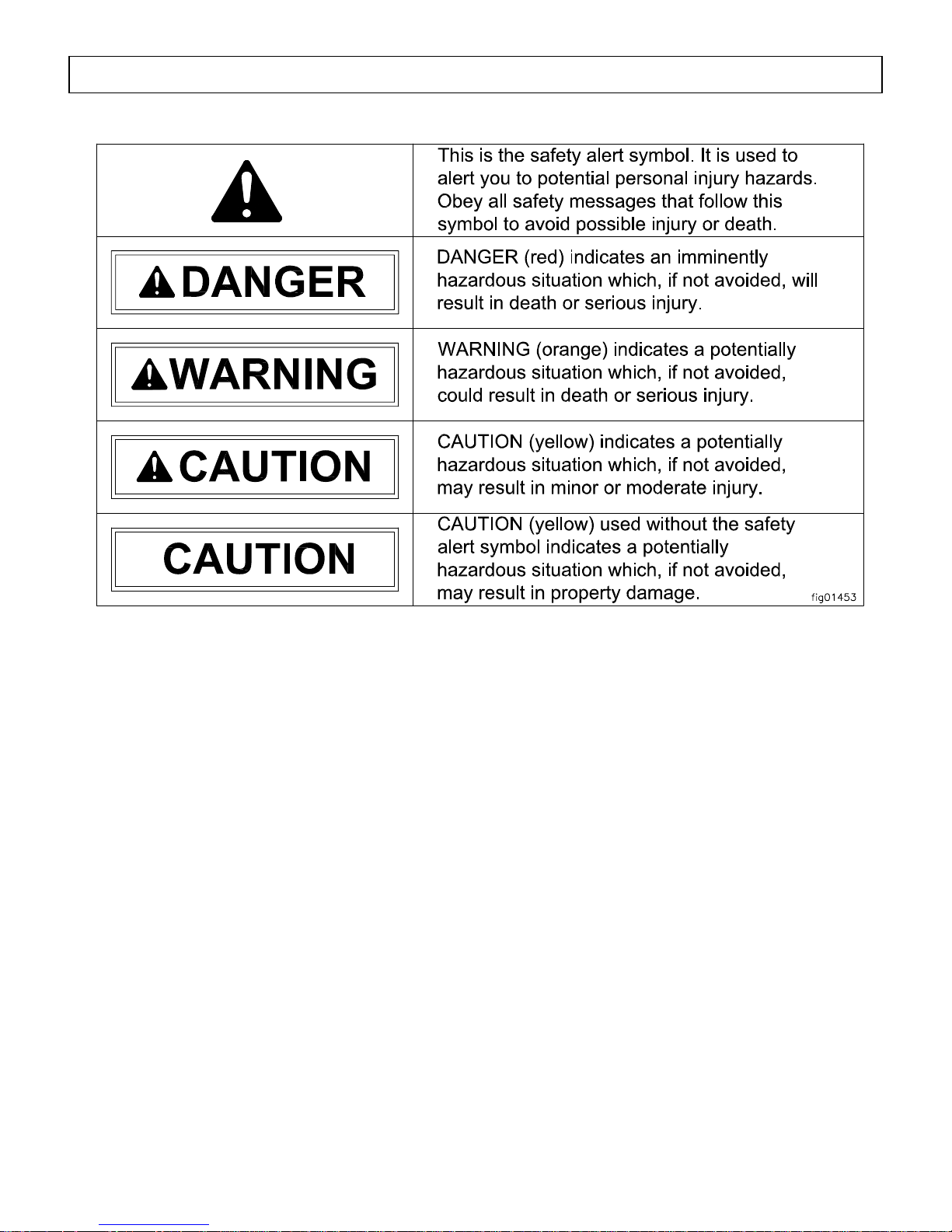
Hazard Signal Word Definitions
2

Table of Contents
Hazard Signal Word Definitions .................................................................................................2
About Your Generator .................................................................................................................4
Specifications .................................................................................................................................6
Safety Label Locations..................................................................................................................7
Machine Component Identification.............................................................................................8
Power Load Planning & Management........................................................................................10
Installation / Initial Set-Up:
1. Unpacking & Delivery Inspection..........................................................................................12
2. Planning the Power Load........................................................................................................13
3. Set-up as a PORTABLE or BUILDING BACK-UP Power Source ......................................13
4. Selecting a Suitable Site.........................................................................................................16
5. Mounting the Generator .........................................................................................................18
6. Grounding the Generator........................................................................................................21
Operation:
1. General Safety Rules for Operation .......................................................................................22
2. Preparing for Operation..........................................................................................................24
3. Connecting to the Tractor.......................................................................................................25
4. Starting the Generator.............................................................................................................27
5. Connecting Loads...................................................................................................................27
6. Stopping..................................................................................................................................29
7. Storage & Exercise.................................................................................................................29
Maintenance & Repair..................................................................................................................30
Troubleshooting.............................................................................................................................32
Summary of Important Safety Information for Operation.......................................................33
Generator Exploded View............................................................................................................36
Wiring Diagram.............................................................................................................................38
Gearbox Exploded View...............................................................................................................40
Limited Warranty.........................................................................................................................41
3

About Your Generator
Thank you for purchasing your NorthStar PTO generator!
About Your Generator
This PTO-driven, portable generator is designed to provide up to 12,000 Watts of
electrical power (12,000 watts continuous, 13,000 watts surge). Connected to your tractor’s
power take-off (PTO)*, the generator can supply power:
1. As a portable power source. You can plug appliances directly into the generator’s
electrical outlets.
2. As a back-up, standby power source for a building. A licensed electrician can connect
the generator to your building’s electrical system via the installation of an UL-approved
transfer switch. (See the “Installation & Initial Set-up” section of this manual to learn
more about specific requirements and precautions relating to wiring the generator to your
building’s electrical system.)
* Your tractor’s PTO must produce a minimum of 24 HP at 540 RPM.
You must select a generator adequately sized for your power needs. You need to
determine the power needs of all the appliances/tools you wish to power at the same time and
choose a generator rated to provide at least that power level. See the “Power Load Planning &
Management” section of this manual to determine your specific power load requirements and
then compare them to this generator’s rated capacity. You must not overload the generator.
Overloading will cause damage to the generator and attached electrical devices, and may also
result in fire.
This generator must be mounted on a reinforced concrete slab or a PTO generator
trailer, so that the generator will not flip during use due to the rotational force of the PTO.
The slab or trailer must be of adequate size and strength to withstand operating torque without
flipping or structural failure. A trailer designed specifically for use with PTO generators rated
up to 60,000 Watts is available from NorthStar -- Item #165959. In order to mount to a
concrete slab, you will need to use the optional mount kit – NorthStar item #165935. More
detailed information about mounting can be found in the “Installation / Initial Set-Up” section
of this manual.
Be sure to read about site selection and grounding requirements for running this
generator. More detailed information can be found in the “Installation & Initial Set-up, Steps
5 & 6” of this manual.
Optional accessories available from NorthStar include PTO drivelines, UL-approved transfer
switches, and extension cords. Contact NorthStar Product Support at 1-800-270-0810 with
questions about optional accessories or to order.
Improper use or maintenance of this generator can result in serious injury or death from
carbon monoxide poisoning, electric shock/electrocution, entanglement, fire, or burns. In
addition,
improperly secured.
PTO shaft and generator can become airborne and cause severe injury if
Read this manual completely before using the generator and follow all instructions and
safety rules.
Read this Manual
WARNING
4

About Your Generator (cont’d)
You must follow all instructions and safety precautions presented throughout this manual. A
summary of important safety information can be found at the end of the manual. Keep this
manual for reference and review.
Proper preparation, operation, and maintenance will result in operator safety as well as best
performance and long life of the generator. Failure to follow the instructions in this manual
for proper mounting, set-up, operation, and maintenance of the generator will void the
manufacturer’s warranty.
Before using, the user shall determine the suitability of this product for its intended use and
assumes liability therein. The purchaser and/or user shall assume liability for any modification
and/or alterations of this equipment from original design and manufacture, or for any nonstandard application, or for use as a subcomponent in another piece of equipment.
NorthStar is constantly improving its products. The specifications outlined herein are subject
to change without prior notice or obligation.
Contact NorthStar Product Support at 1-800-270-0810 for any questions about the
appropriate use of this generator.
Warranty Registration
Please fill out and submit the warranty registration card so that we have your contact
information for any future product literature or replacement parts you may need.
ATTENTION:
All Rental Companies and Private Owners who loan this
All persons to whom you rent/loan this generator must have access to and read this manual.
Keep this owner’s manual with the generator at all times and advise all persons who will
operate the machine to read it. You must also provide personal instruction on how to safely
operate the generator and remain available to answer any questions a renter/borrower might
have.
equipment to others!
5

Specifications – Item #165929
SPECIFICATIONS
Item Number 165929
Maximum Output 13000 Watts (W)
Continuous Output 12000 Watts (W)
Voltage 120 / 240 Volt (V)
Phase Single phase (4-wire)
Frequency 59.0-63.0 Hertz (Hz)
Power Factor 1.0
Minimum PTO HP 24 HP at 540 RPM
Minimum Operating Torque 169.6 pound-foot
Input Shaft 1-3/8” Diameter, 6 spline
120V Receptacle (2) 20 Amp (A) duplex (NEMA 5-20R)
30 Amp (A) locking device
(NEMA L5-30R)
120/240V Receptacle 50 Amp (A) Straight blade (NEMA 14-50R)
Circuit Breaker (2) 20 Amp (A) thermal, push to reset style
30 Amp (A) thermal, push to reset style
(2) 40 Amp (A) thermal, push to reset style
Gear Box
Gear Ratio 1:7
Gear Oil SAE 90W
Oil Capacity .86 Qt. (.82 L)
Dimensions
Length 28.38” (72.1 cm)
Width 14.25” (36.2 cm)
Height 12.50” (31.1 cm)
Gross Weight 127 lb. (57.7kg)
6
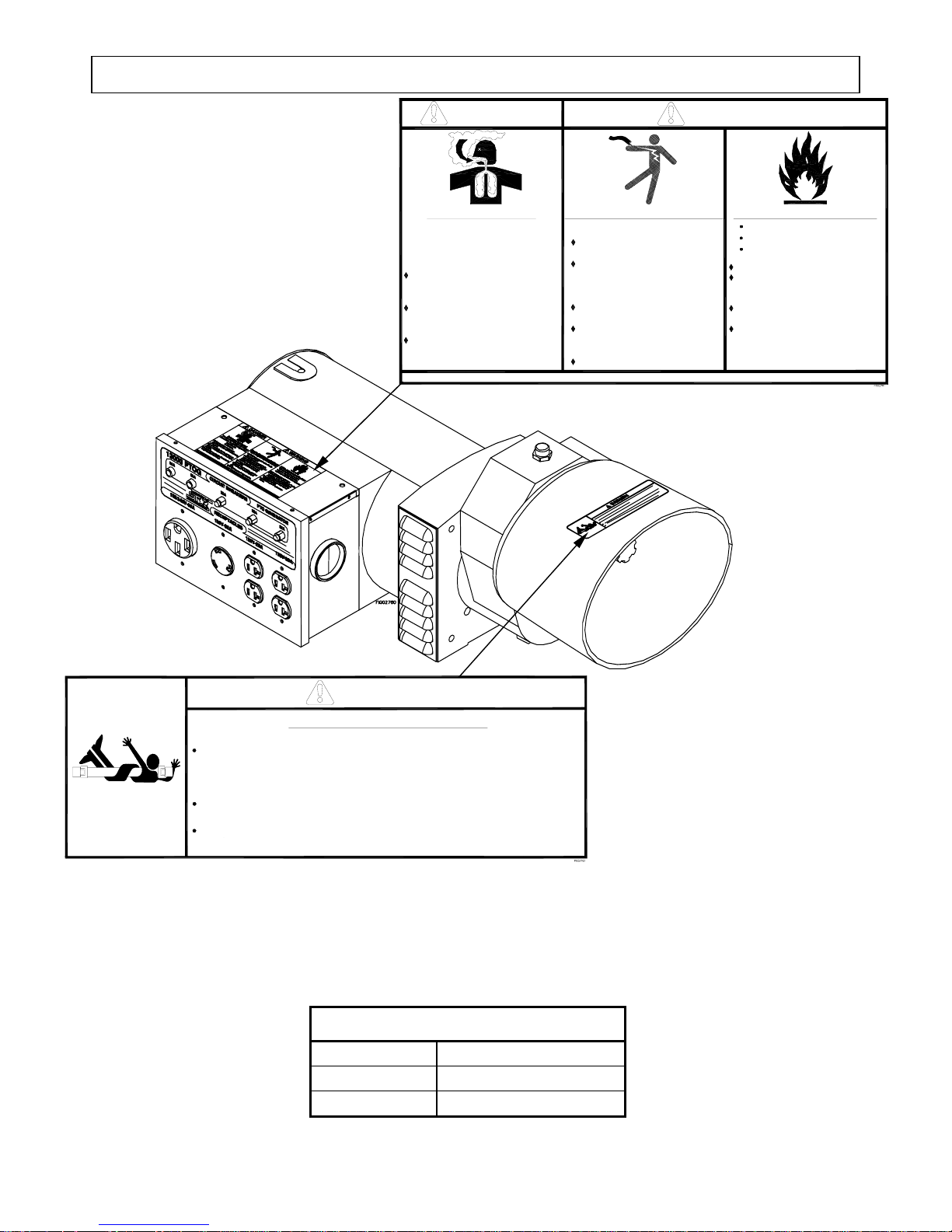
Safety Label Locations – Item #165929
DANGER
WARNING
Poisonous Gas Hazard
Tractor engines give off carbon
monoxide, an odorless gas that
ONLY run tractor & generator
OUTDOORS and AWAY from building
air intakes.
Never run inside homes, garages, or
sheds, EVEN if you run a fan or open
windows.
Install carbon monoxide alarms inside
nearby structures/buildings.
Read Owner’s Manual completely before using. Serious injury or death can result if safety directions are not followed.
can kill you
in minutes.
Electric Shock/Electrocution Hazard
High voltage from generator can kill.
NEVER connect generator directly
into a wall outlet.
ANY connection to a building’s
electrical system MUST ISOLATE
GENERATOR FROM UTILITY
POWER via a transfer switch.
Be sure generator is properly
grounded.
Use only outdoor−rated, grounded
GFCI extension cords of proper
size.
DO NOT operate in wet locations.
A Fire Hazard can arise from:
Overloading the generator
Lack of cooling ventilation
Contact with hot tractor exhaust
DO NOT overload generator.
OPERATE ONLY with adequate cooling
ventilation. Keep all objects at least
7 feet from generator vent openings.
Keep tractor exhause away from all
combustible objects.
ALWAYS keep a fire extinguisher
nearby.
Always make sure safety labels are in place and in good condition. If a safety label
is missing or not legible, order new labels or unsafe operation could result.
To order replacement safety labels, call NorthStar Product Support at 1-800-270-0810.
Driveline guard, plus tractor and generator shields must be in place. Driveline
guard must turn freely and independently on driveline.
Accidental contact with rotating driveline will cause hair or clothing near
rotating shaft to become rapidly entangled.
Driveline must be securely locked at both ends.
An unlocked PTO shaft can whip or become dangerously airborne.
Generator must be properly mounted in accordance with instructions.
Improper mounting may cause generator to filp dangerously during use.
Rotating Driveline/PTO Hazard
Contact with rotating driveline can cause death!
DANGER!
On-Product Warning Labels
Part numbers Description
779781 General Warning
779770 PTO Warning
7
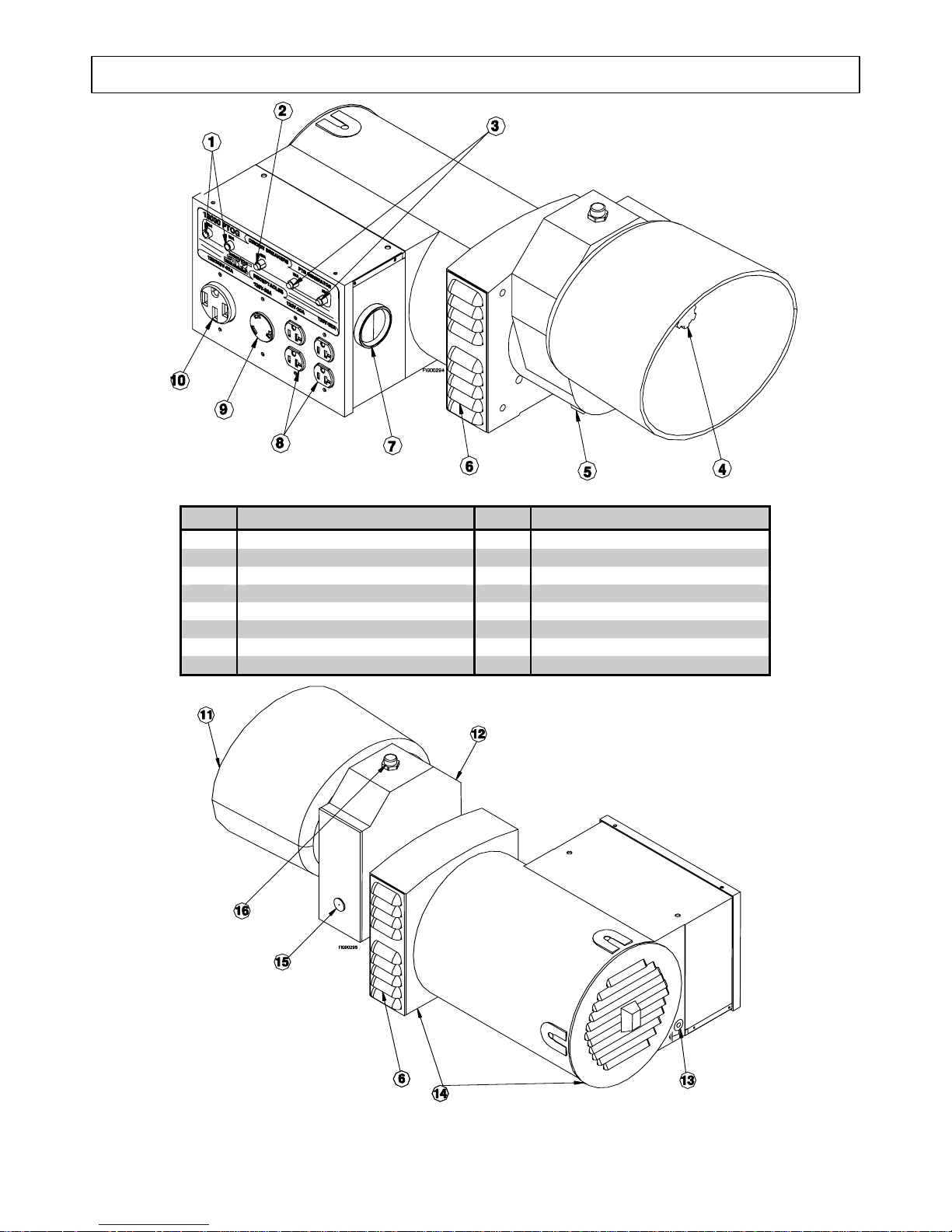
Machine Component Identification - Item #165929G
Figure 1 (Ref 1-10)
Ref. Description Ref. Description
1 50A Circuit Breakers 9 120V 30A Locking Receptacle
2 30A Circuit Breaker 10 120/240V 50A Receptacle
3 20A Circuit Breakers 11 Shield
4 1-3/8”, 6 Spline Input Shaft 12 Gear Box
5 Oil Drain Plug 13 Grounding Screw
6 Fan Vents 14 Mounting Holes
7 Voltmeter 15 Oil Level Sight
8 120V 20A Duplex Receptacles 16 Breather/Oil Fill Plug
Figure 2 (Ref 11-16)
8

Machine Component Identification – Item #165929G (cont’d)
REFERENCE GUIDE
Reference 1 – 50A Circuit
Breakers
Reference 2 – 30A Circuit
Breakers
Reference 3 – 20A Circuit
Breakers
Reference 4 – 1-3/8”, 6 Spline
Input Shaft
Reference 5 – Oil Drain Plug
Reference 6 – Fan Vents
Reference 7 – Voltmeter
Reference 8 – 120V 20A Duplex
Receptacles
Reference 9 – 120V 30A Locking
Receptacle
Reference 10 – 120/240V 50A
Receptacle
Reference 11 – Shield
Reference 12 – Gear Box
Reference 13 – Grounding
Screw
Reference 14 – Mounting Holes
Reference 15 – Oil Level Sight
Reference 16 – Breather/Oil Fill
Plug
Two 50A push-to-reset circuit breakers.
One 30A push-to-reset circuit breaker.
Two 20A push-to-reset circuit breakers.
540 RPM. PTO driveline is available from Northern,
Item #165936.
Change oil after the first 50 hours of use, then after
every 500 hours.
Never block the vent slots or insert objects through the
slots. The closest object should be at least 7 feet
away from the vents.
Voltmeter needle should be in green area during all
generator load conditions. The black line in the center
on the green area indicates 120V. During no load
conditions, the needle should be at or above the black
line.
The generator has a control panel with two 120V 20A
straight blade receptacle duplexes (two receptacles in
a common housing). National Electrical Manufacturer’s
Association (NEMA) number is 5-20R.
This locking device receptacle is a 120V 30A
receptacle, NEMA number L5-30R. This receptacle
accepts NEMA plug number L5-30P.
This straight blade receptacle is 120/240V 50A. This
receptacle accepts a NEMA plug number 14-50P.
Plastic implement shield. NEVER operate generator
without shield in place.
Cast iron housing. 1:7 gear ratio.
Ground the generator via the ground screw, to a
copper pipe or rod that is driven into moist soil.
Use these three locations to mount the generator head
in place with 7/16” grade 5 bolts. Mounting plates
(item #165935) for mounting generator to a cement
pad are available through Northern and the NorthStar
parts catalog.
When oil is even with the red dot, the oil level is
correct. Check oil level daily. Sight is mounted on the
gearbox service panel. If panel is removed for
whatever reason, reseal using Dow Corning sealant
#732.
Use SAE 90W gear oil. Maintain the correct oil level.
Over filling can cause the oil to over heat and damage
seals and bearings. The gearbox is shipped with
temporary plastic plug, remove the caution label and
plastic plug and replace with the breather plug that is
in the manual bag.
9
Power Load Planning & Management
NEVER exceed the rated wattage capacity of your generator.
WARNING
OVERLOADING may cause SERIOUS DAMAGE to the generator and
attached electrical devices, and may result in fire.
Your generator MUST BE SIZED PROPERLY to provide both the running and starting (surge)
wattage of the devices you will be powering. Before using your generator, determine the running
and starting wattage requirements of all the electrical devices you will be powering simultaneously.
The sum of the running and starting wattages of the devices being powered must not exceed the
continuous output rating of your generator. (The continuous output rating of your generator is listed
in the “Specifications” section of this manual.) Note that:
• Devices without electric motors such as light bulbs, radios, and televisions have the same
running and starting wattage.
• Devices with electric motors such as refrigerators, compressors, and hand tools typically
require a starting wattage that is 3 to 5 times greater than the running wattage.
The running and starting wattage requirements are often listed on a device’s nameplate. If wattage
is not given on the device’s nameplate, the wattage may be calculated by multiplying the nameplate
voltage by nameplate amperage, Watts = Volts X Amps.
Example conversion to watts:
120 Volts X 5 Amps = 600 Watts
If only the running voltage is given on the nameplate for a device with an electric motor, the starting
wattage can be approximated to be three to five times the running wattage.
Estimates for the running wattage requirements for common devices are listed in Table 2 below.
Guidance for starting wattages is provided in the table’s footnotes.
Table 2
Device
Air conditioner (12.000 BTU) 1700 (a,b) Jet pump 800 (a)
Battery charger (20 Amp) 500 Lawn mower 1200
Belt sander (3”) 1000 Light bulb (100 Watt) 100
Chain saw 1200 Microwave oven 700
Circular saw (6½”) 2000 (a,b) Milk cooler 1100 (a)
Coffee maker 1800 (a,b) Oil burner on furnace 300
Compressor (1 HP) 1400 (a,b) Oil-fired space heater (140,000 Btu) 400
Compressor (3/4 HP) 1800 (a) Oil-fired space heater (85,000 Btu) 225
Compressor (1/2 HP) 1400 (a) Oil-fired space heater (30,000 Btu) 150
Curling iron 700 Oven 4500
Dishwasher 1200 Paint sprayer, Airless (1/3 HP) 600 (a)
Edge trimmer 500 Paint sprayer, Airless (handheld) 150
Electric nail gun 1200 Radio 200
Electric range (1 element) 1500 Refrigerator 600 (b)
Electric skillet 1250 Slow cooker 200
Running
Watts Device
Running
Watts
10

Power Load Planning & Management (cont’d)
Device
Furnace fan (1/3 HP) 1200 (a) Submersible pump (1-1/2 HP) 2800 (a)
Freezer 800 (b) Submersible pump (1 HP) 2000 (a)
Hair dryer 1200 Submersible pump (1/2 HP) 1500 (a)
Hand drill (1”) 1100 Sump pump 600 (a)
Hand drill (1/2”) 875 Table saw 2000 (a)
Hand drill (3/8”) 500 Television 500
Hand drill (1/4”) 250 Toaster 1000
Hedge trimmer 450 Vacuum cleaner 250
Home computer 150 VCR 70
Impact wrench 500 Water Heater 3000
Weed trimmer 500
(a) Hard-starting motors require 3-5 times the rated running watts
(b) For extremely hard to start loads such as air conditioners and air compressors, consult the equipment dealer to
determine maximum wattage
Running
Watts Device
Running
Watts
To calculate the running and starting wattage requirements for the devices you will be
powering, follow these steps:
1. Make a list of all electrical devices you will be powering at the same time with the generator.
2. List the greater of the running or starting wattage next to each device as obtained from the
devices’ nameplate or Table 2. If only the running wattage for a device with an electric
motor is known, the starting wattage can be estimated to be at least 3 times the running
wattage.
3. Add the wattages for all devices on your list. This total must be lower than the continuous
output rating of your generator.
Example:
Device to be Powered
Starting/Running Wattage
Greater of
Light Bulb 75 W
Refrigerator – 18 Cu. Ft. 1600 W
Microwave 700 W
Window AC 1800 W
Sump pump (1/3 hp) 2100 W
Total 6275W
In this example, the generator must have a continuous output of at least 6275 W in order to
power all of the devices simultaneously.
STAGGERING LOADS
You can increase the number of devices your generator can power by staggering the load on the
generator. For example, you could alternately power your refrigerator and air conditioner for
limited periods of time -- powering only one of the devices at a time and never powering both at the
same time.
11
Installation / Initial Set-Up
There are a number of important steps required to set up your generator for initial use. These
steps are:
Each of these steps is discussed in detail below:
Steps for Installation / Initial Set-Up
1. Unpacking & delivery inspection.
2. Planning the power load to stay within the generator’s rated
capacity.
3. Setting up generator for the type of power generation you need:
a. portable power source, or
b. connected to a building as a back-up power source.
4. Selecting a site for using the generator.
5. Mounting the generator.
6. Grounding the generator.
1. Unpacking & Delivery Inspection
1. You should inspect the generator immediately after you receive delivery.
See the “Machine Component Identification” section of this manual for a
diagram of the generator and its components.
• If you have missing components, contact Product Support at 1-800-270-0810.
• If you have damaged components, contact the freight company that delivered the unit and
file a claim.
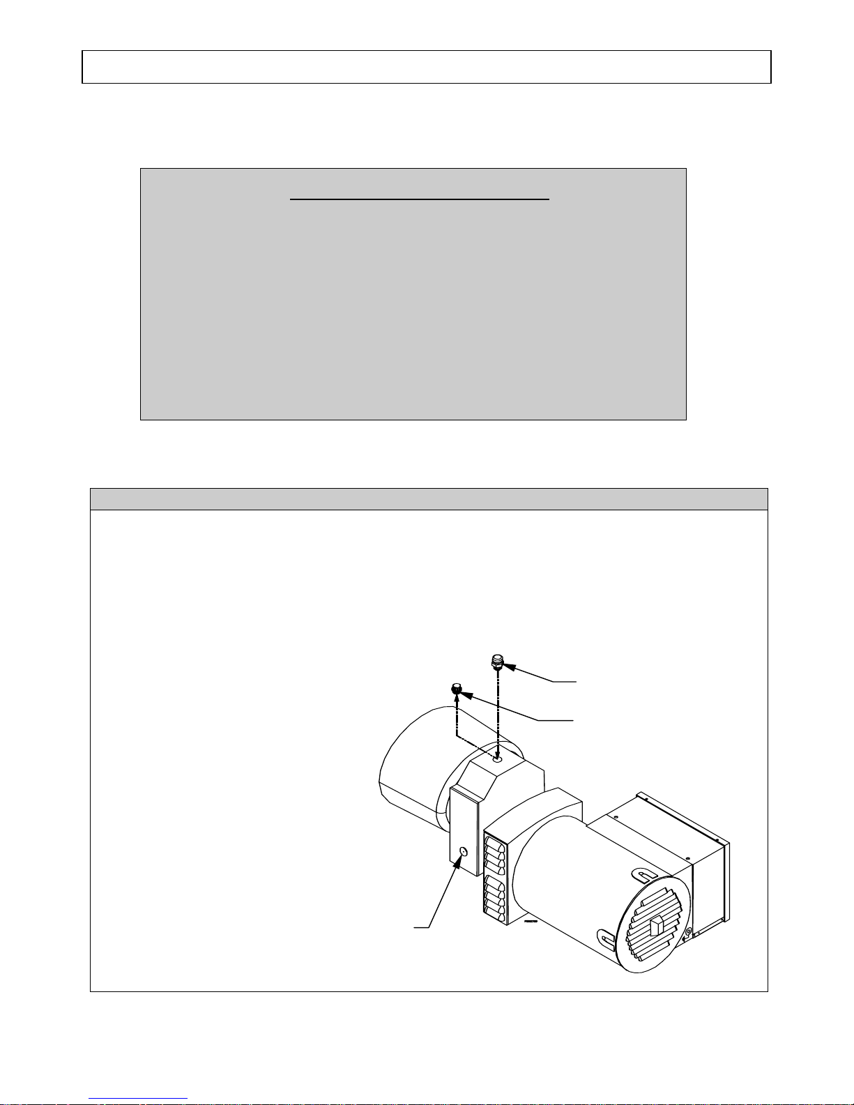
2. The gearbox is shipped with oil
and a temporary shipping plug.
a. Remove the temporary
Filler/Breather Plug
Shipping Plug
shipping plug and replace
with the metal breather/oil
fill plug that is in the
manual bag.
b. Make sure that the gear oil
level is in the middle of
the sight glass, at the red
dot. Add SAE 90W gear
oil as required.
Sight Glass
12
Installation / Initial Set-Up
2. Planning the Power Load
Plan your power load so that you do not exceed the generator’s rated capacity.
See the “Power Load Planning & Management” section of this manual to review how to plan and
manage power loads for the generator.
3. Set-up either as a BUILDING BACK-UP or PORTABLE Power Source
This generator is designed to provide up to 12,000 Watts of continuous electrical power. It can
supply electricity in two ways:
1. As a back-up, standby power source for a building. For this application, you must arrange
for a licensed electrician to connect the generator to your building’s electrical system via the
installation of an UL-approved transfer switch
accordance with building electrical code and guidelines supplied by your power company.
2. As a portable power source. You can plug appliances or tools directly into the generator’s
electrical outlets.
Specific requirements for each are given below.
Note: Regardless of whether you use your generator as a back-up power source connected to a
building or as a portable power source, you must not overload the generator. Overloading
may cause serious damage to the generator and attached electrical devices.
. The transfer switch must be installed in
Using as a
Back-up Power
Source for a
Building
Contact a licensed electrician to install a UL-approved transfer switch if
you want to use your generator as a back-up power source for a building.
What does a transfer switch do? It:
a) Safely connects the generator to your building’s electrical system by
isolating your generator from your utility company’s power lines,
AND
b) Connects your generator to a critical subset of your building’s circuits
that are needed for emergency power needs.
If your generator will be connected to your building’s electrical system, it
MUST ALWAYS be isolated from the utility power grid with a UL-approved
transfer switch installed by a licensed electrician in compliance with all
applicable building and electrical codes, and in accordance with guidelines
supplied by your power company.
DANGER:
A transfer switch must be installed in order to isolate your
generator from the utility power grid. If your generator is NOT
properly isolated from the utility system, serious hazards will
arise:
When your generator is running, it’s output will back feed into
♦
the utility power line and transformer that are normally used to
provide you with power. The transformer will step up the
current to the normal line voltage. An unsuspecting utility line
13
 Loading...