

M165911V
ITEM NUMBER: 165911
®
Owner’s Manual
Instructions for Installation/Set-up, Operation, Servicing, & Storage
Portable, Outdoor Use-Only, Gasoline Generator
4,500 Watt Continuous (5,500 Watt Surge) Capacity
Can be used to power individual appliances plugged directly into the generator’s outlets, or as a back-up
connection to a building’s power supply (via a professionally installed UL-approved transfer switch.
SERIAL NUMBER: _____________
WARNING
READ and UNDERSTAND this manual completely before using the generator! Failure to properly set up,
operate, and maintain this generator could result in serious injury or death from carbon monoxide poisoning,
electric shock, fire/explosion, or burns. In particular, be aware of the following hazards:
Generators give off carbon monoxide, a poisonous gas that can kill you. You CANNOT smell it, see it, or taste it.
• ONLY run generator OUTDOORS and AWAY from building air intakes. NEVER run generator inside any enclosed or
semi-enclosed spaces, including homes, basements, garages, s heds , boxes , RVs, boats or pick-up truck beds. These
spaces can trap poisonous gases, EVEN if you run a fan or open windows.
• Install carbon monoxide alarms inside nearby structures/buildin gs (bat t er y -o perat ed , or plug-in with battery backup).
Electric shock / Electrocution
• High voltage electricity from generator can kill. DO NOT operate in wet locations. Be sure generator is properly
grounded. Use only UL-listed, outdoor-rated grounded extension cords of proper size.
• NEVER plug the generator directly into a wall outlet. ANY connection to a building’s electrical system MUST
ISOLATE THE GENERATOR FROM UTILITY POWER via a UL-approved transfer switch installed by a licensed
electrician. Otherwise, back feed from the generator into the power grid could kill utility workers.
• DO NOT overload generator (per rated capacity), and OPERATE ONLY in an area with adequate cooling ventilation so
engine does not overheat. Exhaust can be extremely hot. Keep muffler at least 7’ from all combustible objects.
• All fuels are flammable. Never fuel a running or hot engine. Never pump fuel directly into generator at gas station – use
approved container to transfer fuel. Ensure there are no fuel leaks, and keep sources of sparks and flames away.
• ALWAYS keep a fire extinguisher rated “ABC” nearby.
CO Poisoning
Fire / Explosion
CHOOSE THE RIGHT GENERATOR FOR YOUR NEEDS. See the “Power load Planning & Management” section
of this manual to determine your power load requirements and then compare to the generator’s rated capacity.
INSPECT COMPONENTS: Closely inspect to make sure no components are missing or damaged. See the “Unpacking
& Delivery Inspection” section for instructions on whom to contact to report missing or damaged parts.
ARRANGE FOR PROFESSIONAL INSTALLATION of a transfer switch if you will be connecting the generator to
your building’s electrical system. See the “Installation/Initial Set-Up” section for more information about this
requirement.
Any Questions, Comments, Problems, or Parts Orders
Call NorthStar Product Support 1-800-270-0810
STOP!
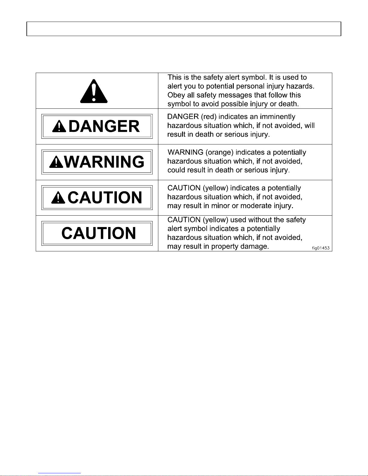
Hazard Signal Word Definitions
2

Table of Contents
Hazard Signal Word Definitions ...................................................................................................2
About Your Generator ...................................................................................................................4
Specifications ...................................................................................................................................6
Safety Label Locations....................................................................................................................7
Machine Component Identification...............................................................................................8
Power Load Planning & Management..........................................................................................10
Installation / Initial Set-Up:
1. Unpacking & Delivery Inspection.......................................................................................... 12
2. Planning the Power Load........................................................................................................ 12
3. Set-up either as a BUILDING BACK-UP or PORTABLE Power Source............................ 13
4. Selecting a Suitable Site......................................................................................................... 16
5. Grounding the Generator........................................................................................................ 18
Operation:
1. General Safety Rules for Operation ....................................................................................... 19
2. Preparing for Operation.......................................................................................................... 22
3. Starting the Engine................................................................................................................. 25
4. Checking Generator Output.................................................................................................... 26
5. Connecting Loads................................................................................................................... 27
6. Stopping the Engine ............................................................................................................... 27
7. Storage & Exercise................................................................................................................. 28
Maintenance & Repair.................................................................................................................. 30
Troubleshooting............................................................................................................................. 32
Summary of Important Safety Information for Operation....................................................... 33
Generator Exploded View............................................................................................................ 37
Wiring Diagram............................................................................................................................. 39
Generator Head Exploded View.................................................................................................. 40
Limited Warranty......................................................................................................................... 41
3
About Your Generator
Thank you for purchasing your NorthStar portable generator!
About Your Generator
This engine-driven, portable generator is designed to provide up to 5500 Watts of
electrical power (4500 watts continuous, 5500 watts surge). It can supply power:
1. As a portable power source. You can plug appliances directly into the generator’s
electrical outlets.
2. As a back-up, standby power source for a building. A licensed electrician can connect
the generator to your building’s electrical system via the installation of an UL-approved
transfer switch. (See the “Installation & Initial Set-up” section of this manual to learn
more about specific requirements and precautions relating to wiring the generator to your
building’s electrical system.)
You must select a generator adequately sized for your power needs. You need to
determine the power needs of all the appliances/tools you wish to power at the same time and
choose a generator rated to provide at least that power level. See the “Power Load Planning &
Management” section of this manual to determine your specific power load requirements and
then compare them to this generator’s rated capacity. You must not overload the generator.
Overloading will cause damage to the generator and attached electrical devices, and may also
result in fire.
Be sure to read about site selection and grounding requirements for running this
generator. More detailed information can be found in the “Installation & Initial Set-up, Steps
5 & 6 of this manual.
This generator is too heavy for one person to lift without mechanical assistance. An
optional wheel kit is available from NorthStar and is recommended if you will be moving the
generator unassisted. Other optional accessories available from NorthStar include a cover for
storage, UL-approved transfer switches, and extension cords.
Contact NorthStar Product Support at 1-800-270-0810 with questions about optional
accessories or to order.
Improper use or maintenance of this generator can result in serious injury or death from
carbon monoxide poisoning, electric shock/electrocution, fire/explosion, or burns.
Read this manual completely before using the generator and follow all instructions and
safety rules.
You must follow all instructions and safety precautions presented throughout this manual. A
summary of important safety information can be found at the end of the manual. Keep this
manual for reference and review.
Proper preparation, operation, and maintenance will result in operator safety, as well as best
performance and long life of the generator. For detailed engine operation and maintenance
information, always refer to the engine Owner’s Manual furnished with the generator.
4
Read this Manual
WARNING

About Your Generator (cont’d)
NorthStar is constantly improving its products. The specifications outlined herein are subject
to change without prior notice or obligation. The purchaser and/or user shall assume liability
for any modification and/or alterations of this equipment from original design and
manufacture.
Before using, the user shall determine the suitability of this product for its intended use and
assumes liability therein.
Contact NorthStar Product Support at 1-800-270-0810 for any questions about the
appropriate use of this generator.
Warranty Registration
Please fill out and submit the warranty registration card so that we have your contact
information for any future product literature or replacement parts you may need.
ATTENTION:
All Rental Companies and Private Owners who loan this
All persons to whom you rent/loan this generator must have access to and read this manual.
Keep this owner’s manual with the generator at all times and advise all persons who will
operate the machine to read it. You must also provide personal instruction on how to safely
operate the generator and remain available to answer any questions a renter/borrower might
have.
equipment to others!
5

Specifications – Item #165911
SPECIFICATIONS
Item Number #165911
Maximum Output 5500 Watts (W)
Continuous Output 4500 Watts (W)
Voltage 120 / 240 Volt (V)
Phase Single phase (4-wire)
Frequency 56.5-63.3 Hertz (Hz)
Power Factor 1.0 p.f.
Engine 9 Hp Honda GX270
Engine Speed 3390 - 3798 RPM
Fuel Type Non-leaded automobile gasoline
Fuel Capacity 6.5 gallons (24.6 L)
Oil Capacity 1.16 US quarts (1.1 L)
Starting Method Recoil
120 V Receptacle 20 Amp (A) duplex (NEMA 5-20R)
120/240 V Receptacle 20 Amp (A) locking device
(NEMA L14-20R)
Circuit Breaker 20 Amp (A) thermal, push to reset
Grounding Post Receives 10 Ga. wire or fork terminal
Dimensions
Length 31.75” (80.6 cm)
Width 23.63” (60.0 cm)
Height 22.25” (56.5 cm)
Dry Weight 180 lb. (82 kg)
Gross Weight 220 lb. (100 kg)
6
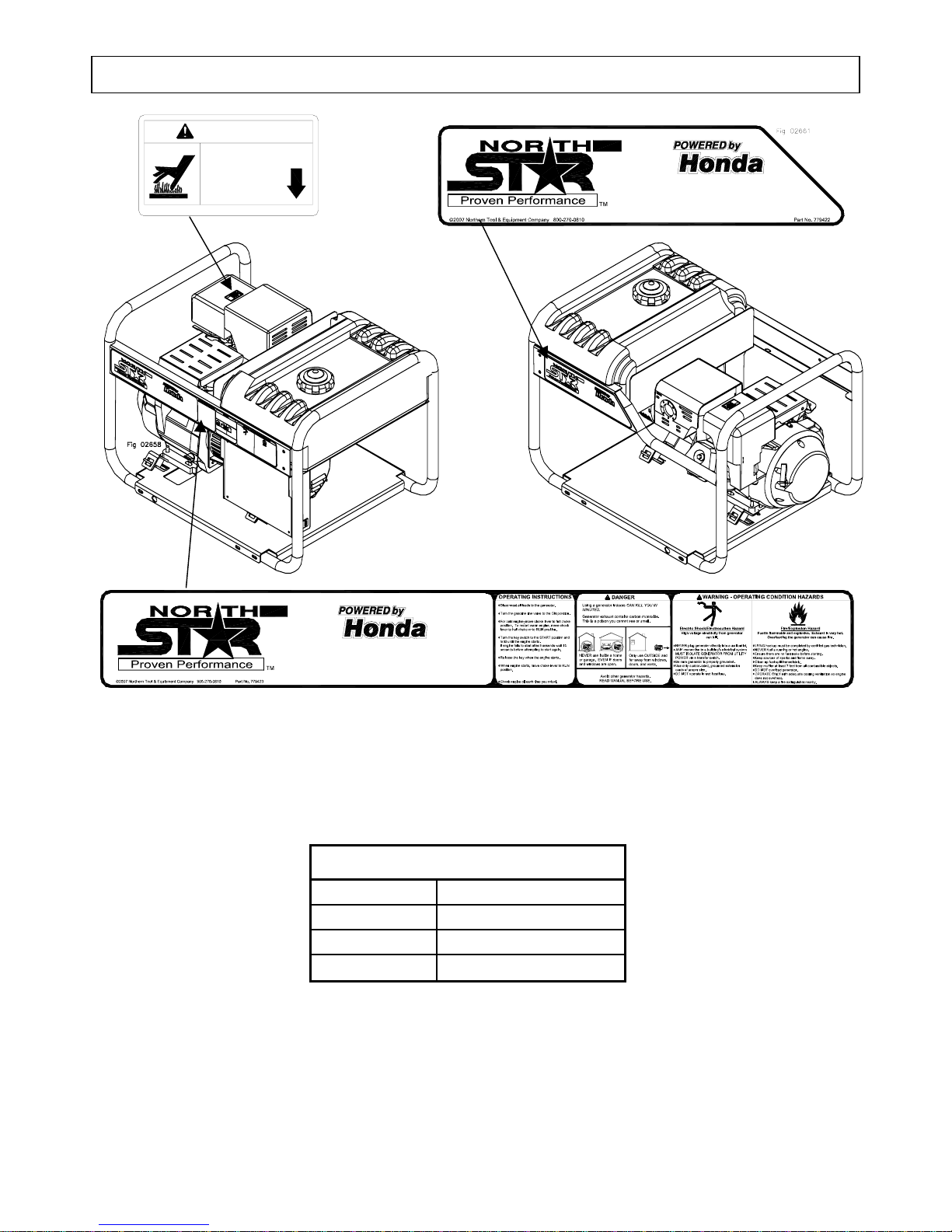
Safety Label Locations – Item #165911
©2005 NT+E 1-800-270-0810
WARNING
BURN HAZARD
Do not touch
hot muffler.
PN 39260
• Commercial-grade electric start engine
• Extend run 6.5 gallon fuel tank
• Maintenance-free brushless alternator design
• Smooth running focus mount isolation sys tem
• Commercial-grade electric start engine
• Extend run 6.5 gallon fuel tank
• Maintenance-free brushless alternator design
• Smooth running focus mount isolation system
Always make sure safety labels are in place and in good condition. If a safety label is
missing or not legible, order new labels or unsafe operation could result.
To order replacement safety labels, call NorthStar Product Support at 1-800-270-0810.
On-Product Warning Labels
Part numbers Description
7
39260 Burn Warning
779422 NorthStar
779423 Warning
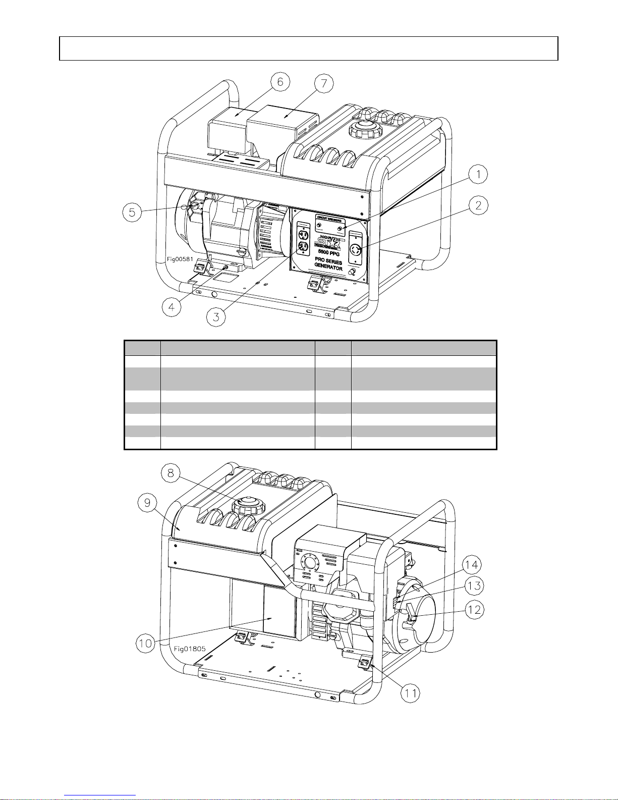
Machine Component Identification – Item #165911V
Figure 1 (Ref. 1-7)
Ref. Description Ref. Description
1 Circuit Breakers 8 Gas Cap with Gauge
2 120/240V 20A Locking
Receptacle
3 120V 20A Duplex Receptacle 10 Generator Head
4 Oil Drain Plug 11 Vibration Isolation Mount
5 Engine On/Off Switch 12 Recoil
6 Air Cleaner 13 Choke Lever
7 Super Silent Muffler 14 Fuel Valve Lever
Figure 2 (Ref. 8-14)
9 6.5 Gal. Gas Tank
8

Machine Component Identification – Item #165911V
REFERENCE GUIDE
Reference 1 – Circuit Breakers
Reference 2 – 120V/240V 20A
Locking Receptacle
Reference 3 – 120V 20A Duplex
Receptacle
Reference 4 – Oil Drain Plug
Reference 5 – Engine On/Off
Switch
Reference 6 – Air Cleaner
Reference 7 – Super Silent
Muffler
Reference 8 – Gas Cap with
Gauge
Reference 9 – 6.5 Gallon Gas
Tank
Reference 10 – Generator Head
Reference 11 – Vibration Isolation
Mount
Reference 12 – Recoil
Reference 13 – Choke Lever
Reference 14 – Fuel Valve Lever
This portable single phase generator has 2, 20 amp
(A) push to reset circuit breakers to protect against
electrical overloads.
The device is a 120/240V 20A NEMA L14-20R
receptacle. This receptacle accepts a NEMA plug
number L14-20P.
ALWAYS use grounded male plugs. The neutral
line of the generator is mechanically grounded to the
frame. Matching NEMA male plugs must always be
used.
The generator has a control panel with one duplex
(two receptacles in a common housing) receptacle
and one locking receptacle. The duplex is a 120 volt
(V) 20 amp (A) straight blade receptacle, National
Electrical Manufacturer’s Association (NEMA)
number 5-20R. This receptacle accepts NEMA plug
numbers 5-15P and 5-20P. Each receptacle on the
duplex is capable of drawing 20A.
Refer to your Honda engine manual for oil change
recommendations.
The red engine stop switch is located on the engine.
Always locate this switch and be familiar with its
location before operating the generator.
Refer to your Honda engine manual for air cleaner
care.
3 dB less than Honda’s engines standard muffler.
The gas cap is extra large, creating a large hole for
refilling and a comfortable grip. You can always
monitor the fuel level without removing the cap by
using the fuel level indicator built into the gas cap.
Large tank allows for extended run capabilities.
Always allow room for gasoline expansion by not
filling the gas tank completely full.
The electricity producing part of the generator.
The engine and generator are mounted on rubber
cylinders that absorb most of the engine vibration.
This feature eliminates the tendency of the machine
to “walk” which is common in engine-powered
equipment.
Grasp firmly when starting engine.
Used during cold starts. Refer to the Honda engine
manual for usage.
The Honda engine has an ON-OFF valve. Always
keep this valve closed when the generator is not in
use. Always keep this valve closed while transporting
the generator.
9
Power Load Planning & Management
NEVER exceed the rated wattage capacity of your generator.
OVERLOADING may cause SERIOUS DAMAGE to the generator and
attached electrical devices, and may result in fire.
Your generator MUST BE SIZED PROPERLY to provide both the running and starting (surge)
wattage of the devices you will be powering. Before using your generator, determine the running
and starting wattage requirements of all the electrical devices you will be powering simultaneously.
The sum of the running and starting wattages of the devices being powered must not exceed the
continuous output rating of your generator. (The continuous output rating of your generator is listed
in the “Specifications” section of this manual.) Note that:
• Devices without electric motors such as light bulbs, radios, and televisions have the same
running and starting wattage.
• Devices with electric motors such as refrigerators, compressors, and hand tools typically
require a starting wattage that is 3 to 5 times greater than the running wattage.
The running and starting wattage requirements are often listed on a device’s nameplate. If wattage
is not given on the device’s nameplate, the wattage may be calculated by multiplying the nameplate
voltage by nameplate amperage, Watts = Volts X Amps.
Example conversion to watts:
120 Volts X 5 Amps = 600 Watts
If only the running voltage is given on the nameplate for a device with an electric motor, the starting
wattage can be approximated to be three to five times the running wattage.
Estimates for the running wattage requirements for common devices are listed in Table 1 below.
Guidance for starting wattages is provided in the table’s footnotes.
Table 1
Device
Air conditioner (12.000 BTU) 1700 (a,b) Jet pump 800 (a)
Battery charger (20 Amp) 500 Lawn mower 1200
Belt sander (3”) 1000 Light bulb (100 Watt) 100
Chain saw 1200 Microwave oven 700
Circular saw (6½”) 2000 (a,b) Milk cooler 1100 (a)
Coffee maker 1800 (a,b) Oil burner on furnace 300
Compressor (1 HP) 1400 (a,b) Oil-fired space heater (140,000 Btu) 400
Compressor (3/4 HP) 1800 (a) Oil-fired space heater (85,000 Btu) 225
Compressor (1/2 HP) 1400 (a) Oil-fired space heater (30,000 Btu) 150
Curling iron 700 Oven 4500
Dishwasher 1200 Paint sprayer, Airless (1/3 HP) 600 (a)
Edge trimmer 500 Paint sprayer, Airless (handheld) 150
Electric nail gun 1200 Radio 200
Electric range (1 element) 1500 Refrigerator 600 (b)
WARNING
Running
Watts Device
Running
Watts
10
Power Load Planning & Management (cont’d)
Device
Electric skillet 1250 Slow cooker 200
Furnace fan (1/3 HP) 1200 (a) Submersible pump (1-1/2 HP) 2800 (a)
Freezer 800 (b) Submersible pump (1 HP) 2000 (a)
Hair dryer 1200 Submersible pump (1/2 HP) 1500 (a)
Hand drill (1”) 1100 Sump pump 600 (a)
Hand drill (1/2”) 875 Table saw 2000 (a)
Hand drill (3/8”) 500 Television 500
Hand drill (1/4”) 250 Toaster 1000
Hedge trimmer 450 Vacuum cleaner 250
Home computer 150 VCR 70
Impact wrench 500 Water Heater 3000
Weed trimmer 500
(a) Hard-starting motors require 3-5 times the rated running watts
(b) For extremely hard to start loads such as air conditioners and air compressors, consult the equipment dealer to
determine maximum wattage
Running
Watts Device
Running
Watts
To calculate the running and starting wattage requirements for the devices you will be
powering, follow these steps:
1. Make a list of all electrical devices you will be powering at the same time with the generator.
2. List the greater of the running or starting wattage next to each device as obtained from the
devices’ nameplate or Table 1. If only the running wattage for a device with an electric
motor is known, the starting wattage can be estimated to be at least 3 times the running
wattage.
3. Add the wattages for all devices on your list. This total must be lower than the continuous
output rating of your generator.
Example:
Device to be Powered
Starting/Running Wattage
Greater of
Light Bulb 75 W
Refrigerator – 18 Cu. Ft. 1600 W
Microwave 700 W
Window AC 1800 W
Sump pump (1/3 hp) 2100 W
Total 6275W
In this example, the generator must have a continuous output of at least 6275 W in order to
power all of the devices simultaneously.
STAGGERING LOADS
You can increase the number of devices your generator can power by staggering the load on the
generator. For example, you could alternately power your refrigerator and air conditioner for
limited periods of time -- powering only one of the devices at a time and never powering both at the
same time.
11

Installation / Initial Set-Up
There are a number of important steps required to set up your generator for initial use. These
steps are:
Each of these steps is discussed in detail below:
You should inspect the generator immediately after you receive delivery.
• If you have missing components, contact Product Support at 1-800-270-0810.
• If you have damaged components, contact the freight company that delivered the unit and file a
Plan your power load so that you do not exceed the generator’s rated capacity.
See the “Power Load Planning & Management” section of this manual to review how to plan and
manage power loads for the generator.
Steps for Installation / Initial Set-Up
1. Unpacking & delivery inspection.
2. Planning the power load to stay within the generator’s rated
capacity.
3. Setting up generator for the type of power generation you need:
a. portable power source, or
b. connected to a building as a back-up power source.
4. Selecting a site for using the generator.
5. Grounding.
1. Unpacking & Delivery Inspection
See the “Machine Component Identification” section of this manual for a
diagram of the generator and its components.
claim.
2. Planning the Power Load
12
Installation / Initial Set-Up
3. Set-up either as a BUILDING BACK-UP or PORTABLE Power Source
This generator is designed to provide up to 5500W of electrical power. It can supply electricity in
two ways:
1. As a back-up, standby power source for a building. For this application, you must arrange
for a licensed electrician to connect the generator to your building’s electrical system via the
installation of an UL-approved transfer switch
accordance with building electrical code and guidelines supplied by your power company.
2. As a portable power source. You can plug appliances or tools directly into the generator’s
electrical outlets.
Specific requirements for each are given below.
Note: Regardless of whether you use your generator as a back-up power source connected to a
building or as a portable power source, you must not overload the generator. Overloading
may cause serious damage to the generator and attached electrical devices.
. The transfer switch must be installed in
Using as a
Back-up Power
Source for a
Building
Contact a licensed electrician to install an UL-approved transfer switch if
you want to use your generator as a back-up power source for a building.
What does a transfer switch do? It:
a) Safely connects the generator to your building’s electrical system by
isolating your generator from your utility company’s power lines,
AND
b) Connects your generator to a critical subset of your building’s circuits
that are needed for emergency power needs.
If your generator will be connected to your building’s electrical system, it
MUST ALWAYS be isolated from the utility power grid with a UL-approved
transfer switch installed by a licensed electrician in compliance with all
applicable building and electrical codes, and in accordance with guidelines
supplied by your power company.
DANGER:
A transfer switch must be installed in order to isolate your
generator from the utility power grid. If your generator is NOT
properly isolated from the utility system, serious hazards will
arise:
♦ When your generator is running, it’s output will back feed into
the utility power line and transformer that are normally used to
provide you with power. The transformer will step up the
current to the normal line voltage. An unsuspecting utility line
worker working on what he thinks is a deactivated line could
be electrocuted.
♦ If your generator is connected (running or not) when utility
power is restored, your generator will be destroyed. It could
also explode or cause fire.
In addition to isolating your generator from the utility system, the transfer
switch connects your generator to a limited set of circuits in your building
that have been chosen as critical to operate during a power outage.
13
 Loading...