

M157598L.1
®
ITEM NUMBER: 157597, 157598
SERIAL NUMBER:
Engine Model:
Pump Model:
Flow:
Hose Length:
Nozzle Size:
Pressure:
Lance Length:
Installation, Operation, and Maintenance Manual
HOT WATER PRESSURE WASHER:
Cleans dirty surfaces with high pressure hot water.
To the Owner:
Thank you for purchasing a NorthStar hot water pressure washer. Your machine is designed for long
life, dependability, and the top performance you demand! Take time now to read through this manual
so you better understand the machines’ operation, maintenance and safety precautions. Everyone
who operates this machine must read and understand this manual. The time you take now will prolong
your machine’s life and prepare you for its safe operation. Enjoy the exceptional performance of your
NorthStar hot water pressure washer, the industry leader! The manufacturer reserves the right to make
improvements in design and/or changes in specifications at any time without incurring any obligation
to install them on units previously sold.
Quick Facts
Engine Oil Engine is shipped without oil. Fill before starting. Use SAE 10W-30 motor oil.
Pump Oil Pump is shipped with oil. Check pump oil level before starting.
Water Make sure your water is clean and particle free and tank fed only. See Installation
instructions.
Storage Do not allow water to freeze in the pump, hoses, coil, or spray guns.
Hose reels Uncoil hose completely before pressurizing with first use.
Electric
Brakes
Spraying
Chemicals
Maintenance
Schedule
Pump: Oil: change after first 40 hours, then every 3 months or 500 hours.
Product 157597 requires an electric brake controller (Brake controllers are available in
our Northern Tool & Equipment Catalogs and Stores).
Use any NorthStar brand or equivalent pressure washer chemicals.
Adjust soap adjustment knob to regulate cleaning power.
Engine: Oil: change after first 20 hours, then annually or every 100 hours.
Check daily.
Spark Plug: clean every 100 hours, replace annually or every 300 hours.
Air Filter: clean every 100 hours, replace annually or every 300 hours.
Mounting Bolts: checked mounting bolts regularly for proper torque
(see maintenance instructions for torque spec)
Read and understand all manuals before operating.
Any Questions, Comments, Problems, or Parts Orders
Call NorthStar Product Support 1-800-270-0810

Table of Contents
Important Safety Instructions 2 Long Term/Winter Storage 15
Specifications 3 Troubleshooting 16
Machine Component Identification 4 Parts Breakdowns 17-20
Installation Instructions 5-6 Electrical Schematic 21
Operation Instructions 7-9 Pump Breakdown 22-23
Safety Features 10-11 California Emissions Statement 24-25
Maintenance Instructions 12-13 Limited Warranty 26
Important Safety Instructions
WARNING -Risk of injection or injury to persons - Do not direct discharge stream at persons. - Do not use a
hose if exterior damage is evident.
-Risk of explosion. Do not spray flammable liquids. Do not operate in a flammable environment.
CAUTION -Risk of asphyxiation. Exhaust fumes are deadly. For outdoor use only. Avoid inhaling exhaust
fumes.
-Risk of fire. Do not add fuel when the product is operating or hot.
-Gun kicks back, hold with both hands.
-To reduce the risk of injury, read and understand operating instructions carefully before use.
WARNING - When using this product basic precautions should always be followed, including the followin g:
1.) Read all the instructions before using the product.
2.) To reduce the risk of injury, close supervision is necessary when the product is used near children. Do
not allow irresponsible use by children. Always stop the product and bleed pressures before leaving
unattended, disconnecting hoses, or servicing the pump.
3.) Know how to stop the product and bleed pressures quickly. Be thoroughly familiar with the controls.
4.) Stay alert - watch what you are doing.
5.) Do not operate the product when fatigued or under the influence of alcohol or drugs. Never smoke while
operating or fueling this machine.
6.) Keep operating area clear of all persons.
7.) Do not overreach or stand on unstable support. Keep good footing and balance at all times. Wear
footwear capable of maintaining a good grip on wet surfaces - Do not place the machine on soft or
unstable ground.
8.) Follow the maintenance instructions specified in all manuals. Do not run machine without sufficient
lubrication or sufficient water to cool the pump.
9.) Wear safety glasses, gloves, face protection and appropriate clothing when operating the machine.
10.) Do not operate this machine with broken or missing parts. - Never alter the manufacturer’s original
design or deactivate any safety device on the machine.
11.) Risk of exposure to dangerous chemicals. Wear protective gloves when handling and cleaning with
chemicals. Follow the chemical manufacturer’s directions. Understand all safety hazards and first aid for
all chemicals being used. Check whether dangerous chemicals have been used and take any
precautions that may have been recommended by the supplier of these chemicals when cleaning filters.
Do not pump highly abrasive fluids or use with incompatible chemicals or solvents.
12.) Know the pressure and temperature limits of your machine. Be sure all high pressure accessories meet
or exceed your machine’s limits. Do not set the pressure relief valve above the machine’s limit.
13.) Do not move this machine by pulling on the hose. Do not use the pump to support other items of
equipment that impose unacceptable loads on the pump. Do not attempt to use this machine as a prop.
14.) To reduce risk of injury, do not secure the spray gun open. Your spray gun is equipped with a built-in
trigger safety latch to guard against accidental trigger release and potentially dangerous high pressure
spray. Rotate the safety latch to the locked position when not spraying.
15.) Do not clean this machine with its own spray. Cleaning should be done with a damp sponge with the
engine OFF.
16.) NEVER attempt to immediately run or re-light the burner if it doesn’t ignite the first time. Unburned oil or
gas may have accumulated causing potential explosion or fire hazard.
17.) Always make sure all switches and controls are in the OFF position prior to starting the engine.
SAVE THESE INSTRUCTIONS
2

Specifications
SPECIFICATIONS
Pressure Rating 4000 psi
Flow Output 7 gpm
Pump Type NorthStar TWS 7040
Water Supply Water feed tank
Engine Horsepower 25 hp
BTU Output 547,400 BTU
Maximum Temperature
Approved Fuel #1 or #2 Diesel, Kerosene, Fuel Oil
Fuel Capacity 15 Gallon
Gasoline Capacity 15 Gallon
Discharge Hose 3/8”
Dimensions (skid only) 47.25” L x 53.75” W x 47.25” H
Weight (skid only) 800 lbs
200° F
SPECIFICATIONS FOR TRAILER MOUNTED MODELS
Trailer GVWR 7000 lbs
Hitch Ball Size 2”
Trailer Dimensions 201.5” L x 78” W x 75” H
Weight (tank empty) 2000 lbs
Weight (tank full) 6550 lbs
3
Machine Component Identification
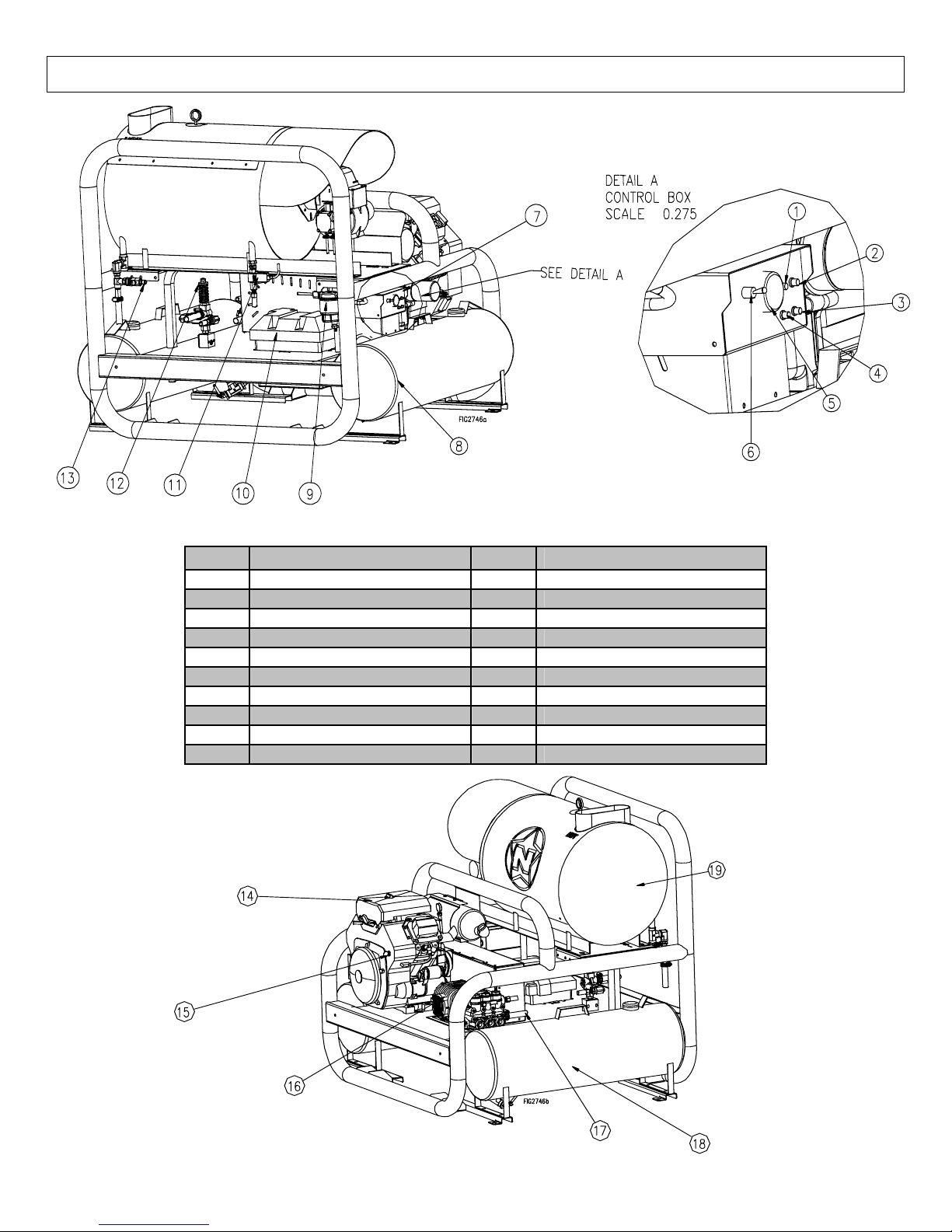
Figure 1 (Ref. 1-13)
Ref # Description Ref # Description
1 Indicator light (Power) 11 Flow Switch
2 Indicator light (Flow) 12 Unloader
3 Indicator light (Burner igniter) 13 Water Outlet
4 Indicator light (Thermostat) 14 Engine (see engine manual)
5 Thermostat 15 Engine Key Switch
6 Heat Switch 16 Pump
7 Control Panel 17 Water Inlet
8 Gasoline Tank 18 Fuel oil/Kerosene/Diesel Tank
9 Raycor Water/Fuel Separator 19 Heat Exchanger
10 Battery box
Figure 2 (Ref. 14-19)
4
Installation Instructions
N
Installing a Battery
Warning: Sulfuric acid is a corrosive poison.
Avoid contact with skin, eyes or clothing. Always
wear safety glasses. Always wear safety glasses
when working on or near the battery.
The engine will not run and the burner will not fire
without first installing a battery.
The battery box provides protection for the battery and
will accept a standard top post mount (Group 75)
automotive battery (The inside dimensions are 11-1/8"L
x 7-3/4"W x 10-1/8"H). The battery must be 12VDC, with
a minimum rating of 18 Ah (Amp-hour). When installing a
battery, always connect the red colored (“positive” or “+”)
cable first. When disconnecting a battery, always
remove the black colored (“negative” or “-”) cable first
Location
IMPORTANT: Proper initial installation of equipment
will assure more satisfactory performance, longer
service life, and lower maintenance cost.
IMPORTANT: The use of a back flow preventer (Part
#222815 call 1-800-270-0810 to order) on the water
supply hose is recommended and may be required
by local code.
Place the pressure washer on a solid level surface in a
protected area where it is not readily influenced by
outside forces such as strong winds, freezing
temperatures, rain, etc. Locate the pressure washer for
easy access for filling fluids, adjustments, controls, and
maintenance. Position the machine so that ambient
lighting is sufficient for the surface you are cleaning to be
seen with ease. Use artificial light if needed.
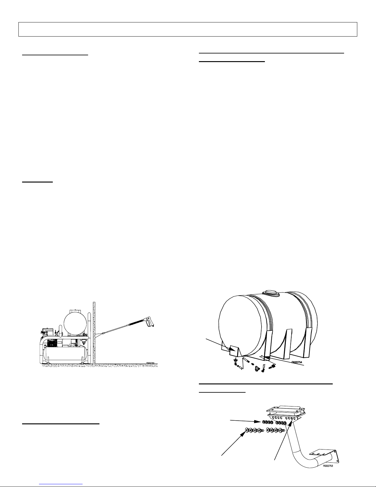
Make a partition between the wash area and the
pressure washer to prevent direct nozzle spray from
coming in contact with the pressure washer. Moisture
reaching the equipment will reduce the pressure
washer’s service life.
Gun Storage (157597 only)
Store guns vertically on back of trailer using supplied
pins. Rest guns with handle down on the back of the
trailer and pins will hold guns in place.
Attaching Customer Supplied Water Feed
Tank (157598 only)
Warning: This unit can only be used with a tank. Direct
feed from a normal city water hookup can cause
cavitation and damage to your pump.
Caution: Make sure to follow these instructions.
Inadequate plumbing between a feed tank and the
pressure washer can cause damage to the pump from
cavitation. Cavitation will occur if you select too small of
fittings and hose to connect the feed tank to the pressure
washer.(We recommend ¾” hose and fittings or larger)
Also, place the pressure washer right next to the feed
tank so the connection hose will be as short as possible.
1.) Drill 1.5” diameter hole in bottom of the tank for the
supply line. Drill a 1.5” diameter hole in the tank at
least 1’ from the supply port for the return line. See
tank in parts explosion of 157597 for an example.
Both holes need to be drilled on flat surfaces of the
tank. Insert supplied bulkhead fittings into holes.
2.) Thread the supplied ¾” elbow fitting into the bulkhead
fitting for the supply line. Thread the supplied ¾”
hose barb fitting into the return line’s bulkhead.
3.) Use supplied ¾” connection hose or supply your own
(can be no longer than 6ft long). Make sure the
connection hose does not kink.
4.) Connect the supply line, from the pump, to the ¾”
elbow with the supplied hose clamp. Connect the
return line, from the unloader, to the ¾” hose barb
using the supplied hose clamp.
5.) Make sure bottom of the tank is level or higher than
the bottom of the skid frame.
6.) Do not pump flammable liquids or liquids containing
incompatible chemicals or solvents.
Supply
Line
Return Line
Insert Nozzles into Hose Reels Guides
(157597 only)
Insert grommets and nozzles into the hose reel
guides.
Grommets
5
ozzles
Insert holes
Installation Instructions
A
A
r
r
Venting
DANGER: Do not run machine indoors or in an
enclosed area without adequate ventilation, or in
areas where flammable vapors, (gasoline, solvents,
etc.) may be present. Do not vent exhaust gases into
a wall, a ceiling, or a concealed place.
CAUTION: All venting must be in accordance with
applicable state and federal laws, and local
ordinances. Consult local heating contractors.
If the pressure washer is to be used in an enclosed area,
a flue must be installed to vent burner exhaust to the
outside atmosphere. Be sure the flue is the same size
as the burner exhaust vent on the pressure washer lid.
Poor draft will cause the pressure washer to soot and
not operate properly. When selecting the location for
installation, beware of poorly ventilated locations or
areas where exhaust fans may cause an insufficient
supply of oxygen. Proper combustion can only be
obtained when there is a sufficient supply of oxygen
available for the amount of fuel being burned. If it is
necessary to install a unit in a poorly ventilated area,
outside fresh air may have to be piped to the burner and
a fan installed to bring sufficient air into the unit. Locate
the pressure washer in such a manner that the flue will
be as straight as possible and protrude through the roof
at a proper height and location to provide adequate draft.
This oil fired unit must have a draft controller installed in
the flue. A draft controller will permit proper upward
airflow of exhaust flue gases.
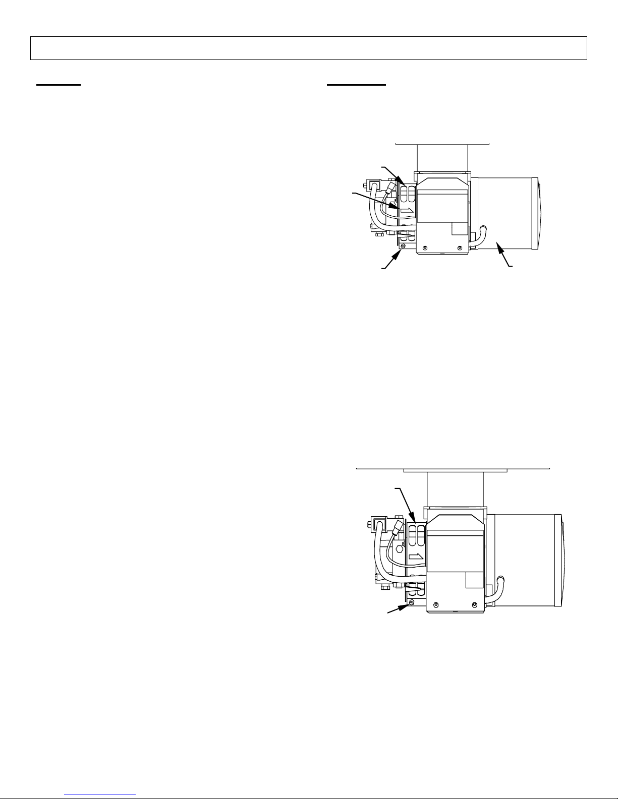
Oil Burner
Burner Air Adjustment: The oil burner is preset and
performance tested at the factory (elevation 1100 feet).
Different altitudes may require a one-time initial burner
correction.
ir Band
White
rrow
Locking
Screw
1.) Turn the engine and heat switches ON (Refer to
“Operation” for details). Have someone operate the
spray gun so the burner fires.
2.) Loosen the locking screw and close the air band until
black smoke appears from the burner exhaust vent.
Note the position of the white arrow on the air band.
3.) Slowly open the air band until white smoke just starts
to appear.
4.) Turn the air band half way back to the black smoke
position previously noted. Tighten the locking
screw.
5.) Fine tune the burner air by loosening the shutter lock
screw and turning the shutter until the exhaust is
cleanest. Tighten the shutter lock screw.
CAUTION: If white smoke appears from the burner
exhaust vent during start-up or operation,
discontinue use and readjust air bands.
NOTE: If a flue is installed, have a professional
serviceman adjust your burner for a #1 or #2 smoke
spot on the Bacharach scale.
Shutte
Shutte
Lock Screw
Burner
6
Operating Instructions
r
r
Read and understand the entire manual before operating the pressure washer.
Follow these instructions every time you use the pressure washer.
I.) Pre-Operation
Read entire manual, especially the important safety
instructions.
1.) Check hoses, fittings, wand, trigger gun and fuel
connections for signs of wear, cracks and
looseness, and replace as required.
2.) Check and clean the nozzle orifice.
3.) Check and clean the water inlet screen and filter.
(see Maintenance section).
4.) Check and maintain proper oil levels in the pump
and engine (see Maintenance section).
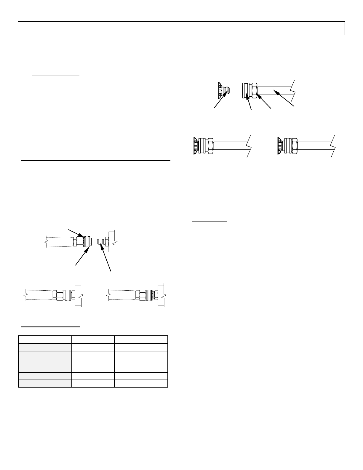
II.) Attach High Pressure Hose (157597 only)
Attach the high-pressure hose to the water outlet. See
Machine Component Identification section for location of
the water outlet
Your pressure washer hose is equipped with quick
couplers. Simply pull the collar back and push the
coupler onto the nipple. Make sure the collar slides over
the ball bearings. Once the connection is made, pull on
the hose to assure a positive connection.
Couple
Colla
CORRECT
III.) Attach Nozzle
Color of Nozzle: Spray Angle Used For:
Red 0 Highest Impact
Yellow 15 Tough Stains/
Green 25 General
White 40 Light Cleaning
Black 65 Chemicals
Your pressure washer is equipped with twelve high
pressure nozzles. Eight #3.5 nozzles and four #7.0
nozzles. There are also three low pressure nozzles
included. To install a nozzle pull the collar back and
push the nozzle into the coupler. Once the connection is
made, pull on the nozzle to assure a tight connection.
High Pressure
Output
INCORRECT
Stripping
Nozzle
WARNING: Make sure the nozzle is correctly
inserted. The nozzle may become a projectile if not
inserted correctly. Do not attempt to use different
types of nozzles that may not fit the coupler.
CORRECT INCORRECT
Collar
Coupler
Lance
Important:
Dual Gun Use
Use two #3.5 nozzles when operating dual guns. This
will ensure the proper flow and psi are achieved for that
application.
Note:
• In dual gun applications, stay aware of the other
gun operator’s location at all times.
• Failure to use two #3.5 nozzles when using two
guns may create a safety hazard. If two
operators use #7.0 nozzles and operator #1
releases the trigger on their gun operator #2 will
receive all 7 GPM. This will cause operator #2’s
gun to kick without warning.
• 157598 OWNERS: Use 2 nipple adapter when
using 2 guns. Remove for single gun use.
Single Gun Use
Use a #7.0 nozzle for single gun operation. This will
ensure the rated flow and psi are achieved. Hook up
both guns when using only a single gun. This stops the
water from exiting the other hose.
7
Operating Instructions
r
r
A
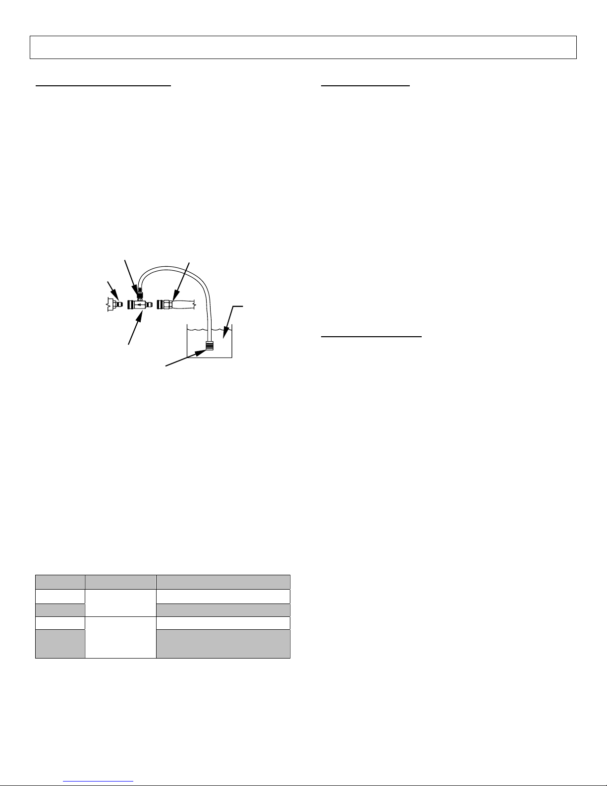
IV.) Applying Chemicals
WARNING: Only use NorthStar pressure washer
chemicals or chemicals specifically formulated for
pressure washers. Follow the chemical
manufacturer’s recommendations. Understand all
safety precautions and first aid for all chemicals.
NOTE: Your pressure washer is equipped with a lowpressure chemical injector. The proper chemical
used for the proper application can speed up
cleaning jobs tremendously.
A.) Snap the quick couple chemical injector onto the high
pressure outlet and high pressure hose and submerge
the suction strainer into the chemical solution.
djustment Knob
High Pressure
B.) You need to use the low pressure black nozzle to
spray chemicals onto the cleaning surface.
C.) The amount of chemical applied can be changed by
turning the chemical adjustment knob located on the
chemical injector.
D.) Squeeze the spray gun trigger. The chemical
injector will draw the chemical into the water stream
E.) Apply chemicals evenly to the cleaning surface.
Allow the chemicals to react with the dirt, then clean at
high pressure with green nozzle.
F.) Never use more chemical than is necessary to clean
the surface.
G.) If you do not intend on using chemicals, we suggest
removing the chemical injector to obtain maximum
cleaning pressure.
Output
Chemical Injecto
Straine
Guns Operation Nozzle (Gun 1/Gun 2)
1
2
1 #7.0 nozzle or any size
2
Applying
Chemical
High
Pressure
High Pressure Hose
Diluted
Chemical
00322
Black
Black/Black
#3.5 nozzle or smaller
#3.5 nozzle or smaller
V.) Start Engine
See the engine manual to start your engine.
IMPORTANT: The water feed tank must contain
adequate water before starting. Running the pump
dry will cause damage and void the warranty. Pump
cavitation can occur.
Note: Engine should be run at full throttle to ensure
proper charging, flow, and pressure is achieved.
Failure to do so may result in poor performance an
inadequate charging for the burner ignition system.
WARNING: Do not inhale the exhaust from the
engine. Do not point the lance at anyone even if the
engine has stopped because there could be a
release of water under retained pressure if the spray
gun trigger is actuated.
VI.) For Hot Water
If HOT water is desired, make sure there is fuel in the
fuel tank, turn the heat switch ON, and adjust the
thermostat to the desired temperature. The burner will
fire when the trigger is squeezed. You may need to
initially adjust your burner for peak performance. See
the “Oil Burner” section under INSTALLATION. When
the trigger is released a pressure switch automatically
turns the burner off. Also, when the temperature setting
is reached, the thermostat automatically turns the burner
off.
IMPORTANT: Do not run the machine in hot mode
without any fuel in the fuel tank. The fuel pump will be
damaged if it is run dry.
Warning: It is important that the burner stops firing when
the trigger is released. If the burner remains firing,
discontinue use until the pressure washer is serviced.
Extremely high temperatures can result in serious injury
and equipment damage.
8
Operating Instructions
VII.) Cleaning
WARNING: Wear eye, ear, hand, foot and skin
protection at all times while operating this pressure
washer.
DANGER: Do not point the spray wand at yourself or
at any person. Bodily injury may result from water
under high pressure.
CAUTION: Be careful on painted or delicate
surfaces. The pressure may damage the surface if
the nozzle is too close.
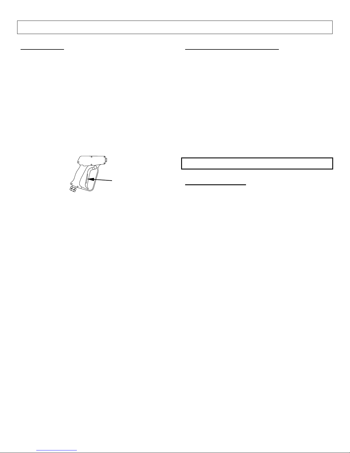
IMPORTANT: Your spray gun is equipped with a
built-in trigger safety latch to guard against
accidental trigger actuation and potentially
dangerous high pressure spray. Rotate the safety
latch to the locked position when not spraying.
00417
A.) Hold the lance with two hands, have a sturdy stance.
B.) The pressure washer is set and locked to the
maximum rated pressure when it leaves the factory. .
WARNING: Do not alter the unloader valve’s
maximum pressure. Excess pressures could
cause serious injury and/or pump damage. Any
alteration other than turning the adjustment knob
will void your warranty.
Safety Latch
VIII.) Shut-Down Instructions
WARNING: Do not leave an operating machine
unattended. Always shut the machine OFF and
relieve the pressure before leaving the machine.
Never disconnect the high-pressure hose from the
pump or spray gun while the system is pressurized.
Relieve pressure by squeezing the spray gun trigger
after the engine is turned OFF.
A. Turn heat switch OFF and run cold water
through the coil for 3 minutes.
B. Turn engine OFF.
C. Actuate spray gun trigger to relieve system
pressure.
D. Remove gun from pressure hose and store
properly.
Safety Features
Safety Relief Valve
The safety relief valve is a backup safety feature. If the
system over pressurizes, the safety relief valve will open
and relieve system pressure.
The safety relief valve is located in the high-pressure line
after the heat exchanger.
WARNING: If the safety relief valve ever discharges
water, turn the engine off and do not use the
machine until it is serviced.
9
 Loading...