

®
M157309M.1
ITEM NUMBER: 157309
SERIAL NUMBER: _____________
Owner’s Manual
Instructions for Set-up, Operation, Maintenance & Storage
HOT WATER/STEAM PRESSURE WASHER – 2750 PSI / 2.5 GPM
Portable Outdoor-Use Only
This pressure washer produces both cold and hot water high-pressure spray as well as steam spray.
Cleaning chemicals may be incorporated into the spray if desired. The pressure pump for this equipment
is powered by a gasoline internal combustion engine and the water is heated by a kerosene/fuel-oil fired,
open flame burner.
READ and UNDERSTAND this Owner’s Manual and the Engine Owner’s Manual
completely before attempting to set up and use the pressure washer! Failure to properly set
up, operate, and maintain this pressure washer could result in serious injury or death to operator
or bystanders.
• Exhaust from both the engine and burner contains carbon monoxide, a
CO Poisoning
Skin/Eye
Injury
Burns
Slips/Falls
Flying Debris
Fire/
Explosion
Chemical
Exposure
Electric shock
A summary of important safety information is provided at the end of the manual.
• High-pressure spray can cause serious skin or eye injury, including injection injury
• Hot spray can scald and burn skin.
• Hot surfaces of wand, engine and burner, as well as hot exhaust from both
• Spray discharge can cause puddles and slippery surfaces.
• Spray-gun kickback can cause operator loss of balance and falls.
• High-pressure spray can cause surface damage and flying debris.
• Engine and burner sparking can ignite fuel or other flammable liquids or
• Hot exhaust from engine and burner can ignite combustible materials.
• Cleaning chemical vapors or contact with skin may be hazardous.
• Spray contact with electrical sources can cause electric shock.
Any Questions, Comments, Problems, or Parts Orders
WARNING – READ THIS MANUAL
WARNING – SPECIAL HAZARDS
poisonous gas that can cause carbon monoxide poisoning and possible
death if inhaled.
if fluid pierces the skin. Injection injury can result in blood poisoning and/or
severe tissue damage.
the engine and burner can cause burns.
vapors in the vicinity.
Call NorthStar Product Support 1-800-270-0810
1
Inspect Upon
Delivery
Fill with
Engine Oil
Check Pump
Battery
Required
Water Flow
Requirements
Storage Do not allow water to freeze in the pump, hose, coil, or spray gun(s).
Chemical
Spraying
Maintenance
Schedule
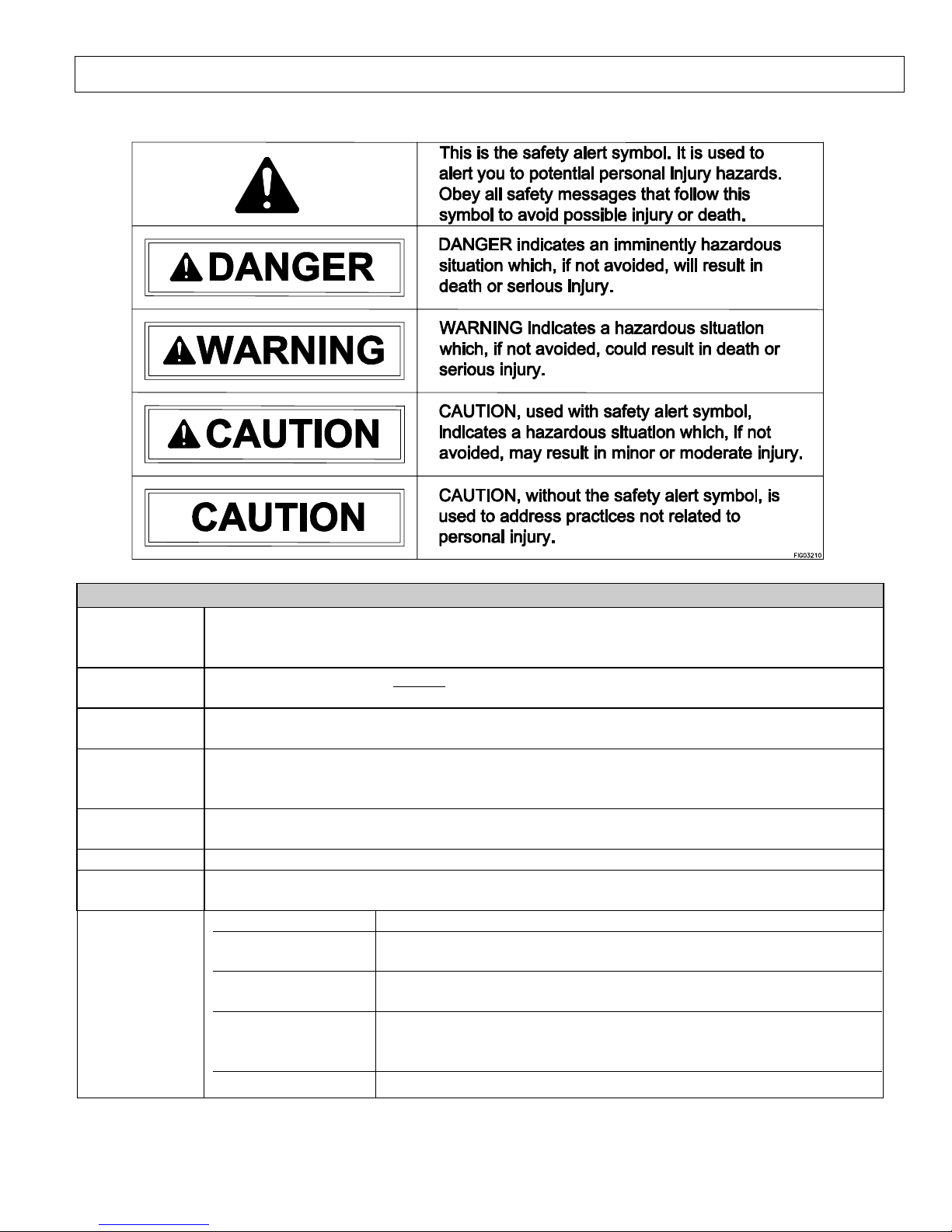
Hazard Signal Word Definitions
Equipment Protection Quick Facts
STOP! Closely inspect to make sure no components are missing or damaged. See the
“Assembly and Initial Set-Up” section for instructions on whom to contact to report missing or
damaged parts.
STOP! Engine is shipped without oil. DO NOT start pressure washer without adding oil to
engine. Please refer to Engine Manual shipped with unit for acceptable grade motor oils.
Oil Pump is shipped with oil. Check pump oil level before starting.
A battery is not included. A battery must be installed before starting the engine or damage to
the engine voltage regulator will result. Purchase a standard 12VDC, 18 Ah lawn and garden
battery (Group U1-7).
Make sure your supply water flow rate is 20% higher than the pressure washer’s flow rate (see
“Specifications” section for detail), and that your water is clean and particle free.
Use only NorthStar brand or equivalent washer chemicals designed for pressure washer use.
Engine: • See Engine Owner’s manual.
Pump:
Burner fuel filter
/water separator:
Coil:
Electrodes: • Inspect electrodes annually and clean/adjust as needed.
• Change oil after first 40 hours, then every 3 months or 500
hours.
• Drain water as needed.
• Change filter after every 500 hours of use
• Descale coil annually or more frequently as conditions /
performance require.
• Inspect coil for soot build-up annually and desoot if needed.
2

Table of Contents
About Your Pressure Washer ........................................................................................................4
Specifications....................................................................................................................................5
Component Identification ...............................................................................................................6
Safety Labeling.................................................................................................................................8
Special Equipment Safety Features................................................................................................9
Assembly and Initial Set-Up ..........................................................................................................10
Step 1. Unpacking & Delivery Inspection ....................................................................................10
Step 2. Assembly...........................................................................................................................12
Step 3. Initial Pump & Engine Preparation...................................................................................13
Step 4. Battery Installation............................................................................................................14
Moving and Handling .....................................................................................................................16
Before Each Use ..............................................................................................................................17
Step 1. Check Equipment..............................................................................................................17
Step 2. Add Fuel(s) .......................................................................................................................18
Step 3. Select a Suitable Worksite................................................................................................20
Operation..........................................................................................................................................22
Step 1. Connect Hose(s), Water Supply, and Spray Nozzle(s).....................................................22
Step 2. Set Up for Chemical Spray (if desired).............................................................................25
Step 3. Spraying............................................................................................................................27
Step 4. Stopping............................................................................................................................33
Storage ..............................................................................................................................................34
Burner Adjustment .........................................................................................................................37
Maintenance and Repair ................................................................................................................39
Troubleshooting...............................................................................................................................50
Parts Explosion ................................................................................................................................51
Wiring Diagrams .............................................................................................................................53
Summary of Important Safety Information .................................................................................56
Limited Warranty ...........................................................................................................................61
3
About Your Pressure Washer
Thank you for purchasing a NorthStar hot water pressure washer! Your machine is designed for long life,
dependability, and the top performance you demand. This pressure washer is designed to:
1) Produce a high-pressure steam spray or water spray (heated or unheated) -- up to 2.5 gallons per minute
at 2750 psi.
2) Incorporate cleaning chemicals into a low-pressure water spray.
The pump requires a clean, standard tap water supply provided through a garden hose at a flow rate of at least 3
gallons per minute. The use of a backflow preventer on the water supply hose is recommended and may be
required by local code. Any cleaning chemicals that are used must be specifically approved for use in pressure
washers.
The pump is powered by a gasoline-fueled engine. The spray water is heated (when desired) by a kerosene/fueloil fired, spark-ignited, open flame burner. Normal operation of this equipment will require you to supply:
• Gasoline fuel and lubrication oil for the engine
• Pump oil
• Fuel for the burner (kerosene, diesel, or fuel oil)
See the “Specifications” section of this manual for more detail.
Gasoline powered pressure washers are for OUTDOOR USE ONLY. Be sure to read about site selection
for running this pressure washer in the “Installation & Initial Set-up” section of this manual.
The user should plan to acquire and wear safety apparel during operation of this pressure washer. Safety apparel
includes waterproof insulated gloves, safety glasses with side and top protection, and non-slip protective
footwear. Some cleaning chemicals may require the use of a respirator mask (as instructed on chemical label).
Before using this washer, the user shall determine the suitability of this product for its intended use
and assumes liability therein.
Keep this manual for reference and review. A summary of important safety information can be found
at the end of the manual.
Proper preparation, operation, and maintenance of this pressure washer will result in optimal
performance and a long life for this equipment. For detailed Engine operation and maintenance
information, always refer to the Engine Owner’s Manual furnished with the pressure washer.
Rental Companies and Private Owners who loan this equipment to others!
All persons to whom you rent/loan this pressure washer must have access to and read this manual. Keep this
owner’s manual with the pressure washer at all times and advise all persons who will operate the machine to
read it. You must also provide personal instruction on how to safely set-up and operate the pressure washer
and remain available to answer any questions a renter/borrower might have.
• A 12-volt standard lawn and garden battery
Read this Manual
Carefully read and follow all instructions and safety information for using this pressure
washer. Improper use or maintenance of the pressure washer can result in serious injury or death
to the operator or bystanders from:
• Carbon monoxide poisoning • Fire/explosion • Chemical exposure
• Skin/eye injury from high
pressure spray
WARNING
• Burns • Slips/falls
• Electric shock • Flying objects/debris
ATTENTION:
4
Specifications
MODEL
Model # 157309
FLOW OUTPUT
Pressure Rating 2750 psi
Flow Rate 2.5 gpm
Maximum Temperature
250° F
DIMENSIONS / COMPONENTS
Length 44”
Width 27”
Height 42”
Weight (fueled) 400 lbs.
Pump Type Comet BXD
Engine Displacement 205cc
High Pressure Discharge Hose 3/8” x 50’
Chemical Injection Point Injection dilution ratio 15-to-1
SUPPLIES REQUIRED (not included)
Engine Fuel Regular, Unleaded Gasoline
Engine Oil See Engine Owner’s Manual
#1 or #2 Diesel, B5 or lower Biodiesel,
Burner Fuel
Pump Oil
(shipped with oil, but refills required)
Battery
Input Water Supply
Input Water Supply Hose
Universal Tractor Transmission Oil or
Lawn and Garden Battery (Group U1-7)
(at least 3/4” diameter if hose longer
Kerosene, or Fuel Oil
(Capacity: 4 Gal.)
Mobil 1 Synthetic 15W-50
12 Volt, minimum 18 Amp/Hr.
Standard tap water @ 20-100 psi,
delivered @ 3.0 gpm or higher
Standard garden hose with inside
diameter at least 5/8”
than 100 ft.)
5
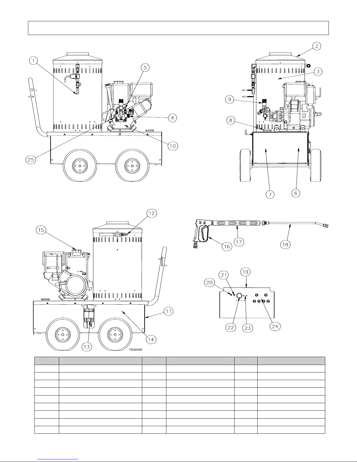
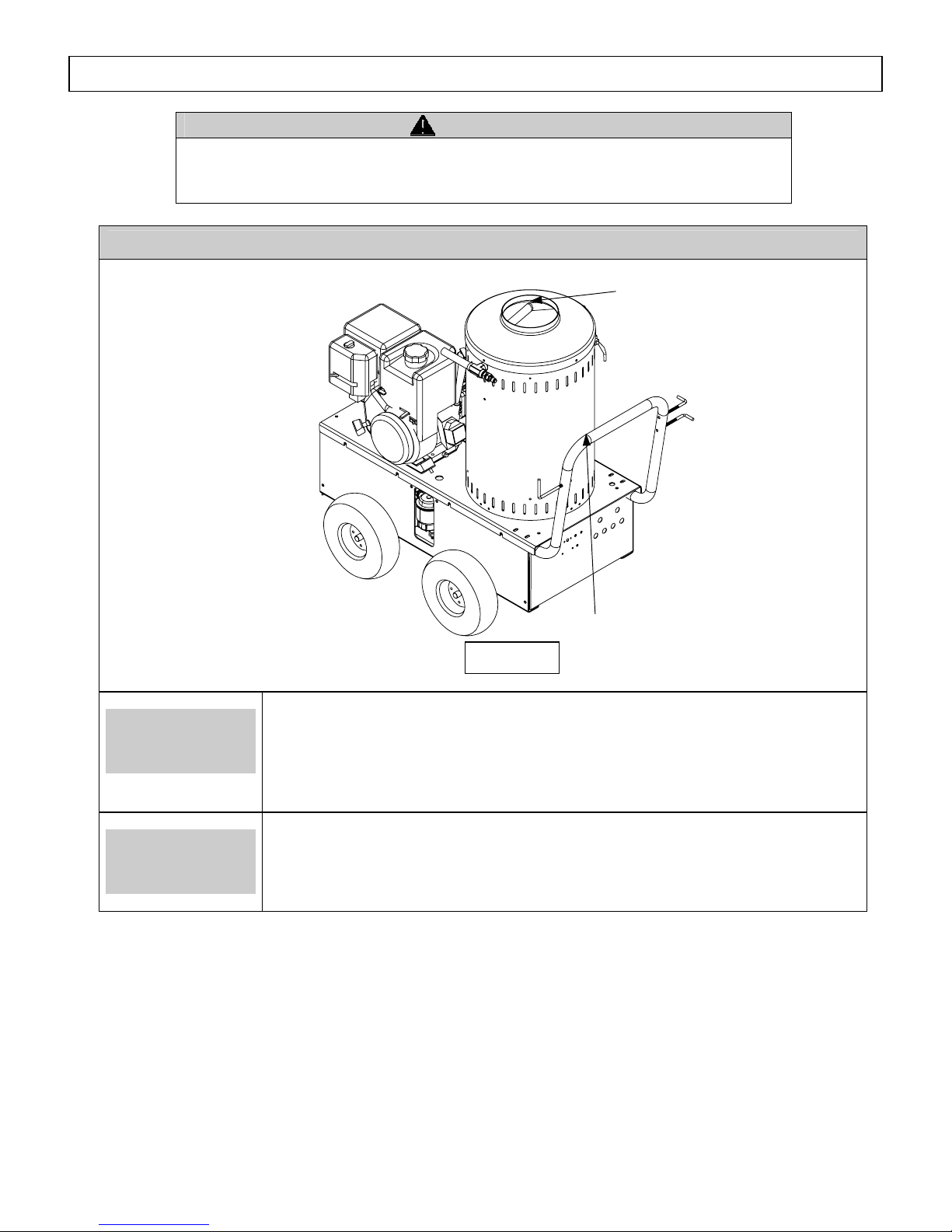
Component Identification
Ref # Description Ref # Description Ref # Description
1 High Pressure Relief Valve 10 Engine 19 Control Panel
2 Exhaust Vent 11 Control Panel 20 Circuit Breaker
3 Heating Coil 12 High Pressure Outlet 21 Heat Switch
4 Garden Hose Water Inlet 13 Fuel Filter 22 Thermostat
5 Pump 14 Burner 23 Indicator Lights LED
6 Battery location 15 Gas Cap 24 Nozzle Storage
7 Fuel Tank 16 Spray Gun 25 Thermal Relief Valve
8 Fuel Cap 17 Grip
9 Unloader 18 Wand
6

Component Identification cont’d
1. High Pressure Relief Valve
2. Exhaust Vent
3. Heating Coil
4. Garden Hose Water Inlet
5. Pump
6. Battery Location
7. Fuel Tank
8. Fuel Cap
9. Unloader
10. Engine
11. Access Panel
12. High Pressure Outlet
13. Fuel Filter / Water Separator
14. Burner
15. Gas Cap
16. Spray Gun
17. Grip
18. Wand
19. Control Panel
20. Circuit Breaker
21. Heat Switch
22. Thermostat
23. Indicator Lights, LED
24. Nozzle Storage
25. Thermal Relief Valve
REFERENCE GUIDE
A safety valve that relieves pressure; to eliminate over
pressurization.
Provides an out for burner exhaust gases.
Steel piping wound together with an inlet for incoming cold
water and outlet for hot water to exit.
Means of connecting garden hose to pump inlet.
A device that moves fluid through a combination of suction
and displacement.
Storage place to house the battery.
Fuel storage container.
Vented cover for fuel tank.
Valve that regulates pressure and directs flow into bypass
when trigger is closed.
The air-cooled engine powers the pump.
Opening to access battery and additional enclosed components.
A passage for water to exit pump and enter the hose.
Filter in fuel line that removed water and screens out dirt and
debris from fuel.
A device used to efficiently convert fuel oil or gas into heat
energy.
Cover for gas tank.
Used to divert water out to nozzle.
Section of wand to extend length and provide stability.
Rod to extend length.
Flat surface for mounting switches.
Trips to open circuits when overloaded.
Acts as an on/off device for power to burner components.
Control power to fuel solenoid for firing.
Instrument used to monitor unit operation.
A space for storing nozzles.
Discharges hot water from the pump manifold during long
bypass operation.
7
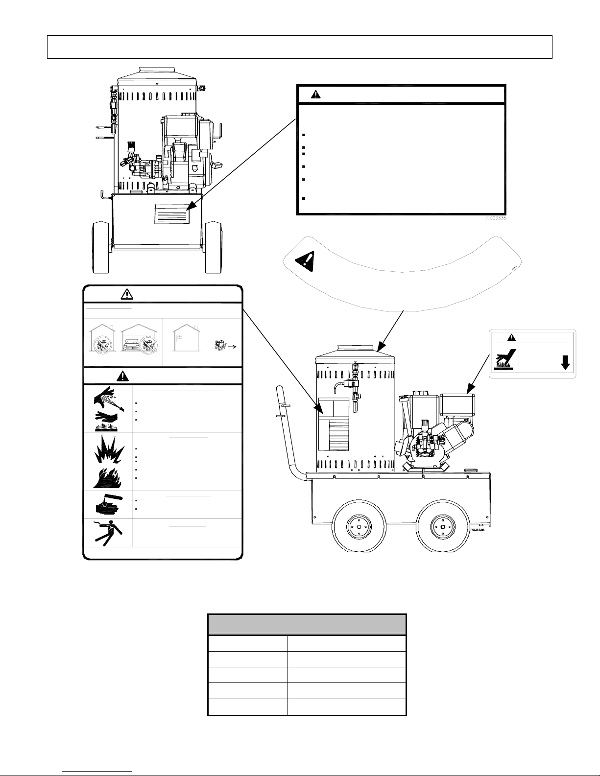
Safety Labeling
FOR OUTDOOR USE ONLY! Using this pressure washer indoors CAN KILL Y OU IN MINUTES.
Engine exhaust and burner exhaust contain carbon monoxide. This is a poison you cannot
see or smell.
DANGER
Always make sure safety labels are in place and in good condition. If a safety label is
missing or not legible, order new labels or unsafe operation could result. To order replacement
safety labels, call NorthStar Product Support at 1-800-270-0810.
NEVER use inside any building, structure or
garage, EVEN IF doors and windows are open.
Only use OUTSIDE and far away from
windows, doors, and vents.
WARNING
High Pressure Fluid Forces / Burn Hazards
High pressure spray can cause injection injury, eye injury, and
loss of balance. Hot discharge fluid and hot surfaces can burn.
NEVER direct discharge stream at or near any person. Do not
allow any part of the body to come in contact with the fluid stream.
Gun kicks back - hold with two hands. Keep good footing and
balance at all times.
Surfaces of engine, burner, and wand can become very hot. Use
only designated gripping area of wand. Avoid contact with hot
engine and burner.
Spraying flammables can cause explosion. Fuel is flammable
and explosive. Exhaust can ignite combustible materials.
NEVER spray flammable liquids. Operate only where open flame
or torch is permitted.
NEVER fuel a running or hot engine or oil burner.
Ensure there are no fuel leaks before starting. Keep sources of
sparks and flames away.
Use approved container only for transferring fuel. Clean up fuel
spills immediately.
Keep engine and burner exhaust at least 7 feet from all
combustible objects. Situate on heat-resistant flooring when
using burner.
Understand all safety hazards and first aid measures for chemicals
being used.
Follow chemical manufacturer's directions when handling and
cleaning with chemicals. Wear safety gear as directed.
Keep spray away from electrical wiring, or electric shock /
electrocution could occur.
CAUTION: To Reduce Risk of Injury, Read Operating Instructions Carefully Before Using.
Fire / Explosion Hazard
Chemical Exposure Hazard
Electric Shock Hazard
782325
WARNING - BATTERY HAZARDS
BATTERIES:
1) contain caustic acid, 2) emit explosive gases,
3) can cause electric shock
ALWAYS use eye protection. Caustic acid and explosive
gases can cause blindness or severe burns.
NO smoking, sparks, or flames.
NEVER touch both battery terminals at the same time with your
hand or any non-insulated tools.
FLUSH immediately with water if battery acid contacts eyes,
skin, or clothing.
CONNECT cables in correct sequence: FIRST RED to POSITIVE
terminal, then BLACK to NEGATIVE terminal. When disconnecting,
DISCONNECT BLACK cable first, then RED.
NEVER charge a visibly damaged or frozen battery. ALWAYS
read and follow charger instructions.
C
A
U
T
I
O
N
H
T
O
782397
!
WARNING
BURN HAZARD
Do not touch
hot muffler.
Northern Tool +Equipment ©
PN 39260
On-Product Warning Labels
Part numbers Description
782325 Danger & Warning
305410 Caution Hot
39260 Hot Muffler
782397 Battery Hazard
8
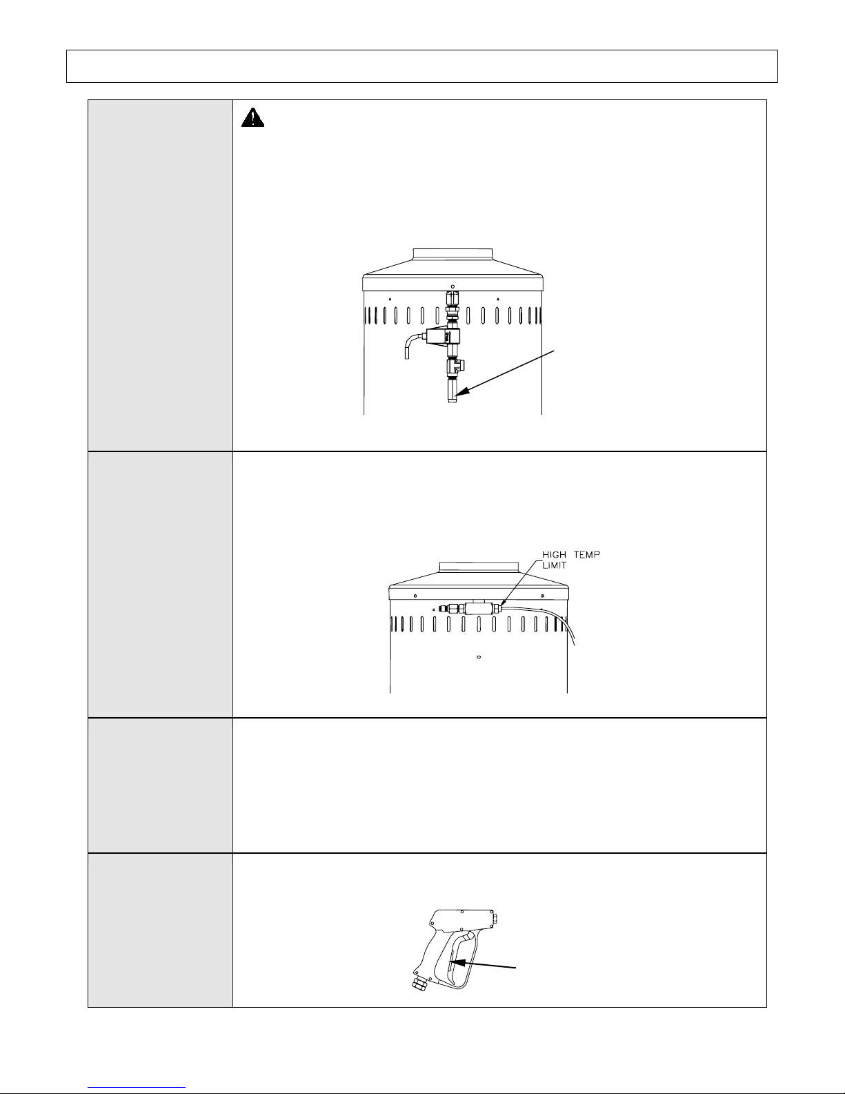
Special Equipment Safety Features
High Pressure
Relief Valve
High
Temperature
Limit
WARNING: If the high-pressure relief valve ever discharges water,
turn the engine off and do not use the machine. Call Product Support at
1-800-270-0810.
This unit is equipped with a high-pressure relief valve, which acts as a backup
safety feature. If the unloader malfunctions, the high-pressure relief valve
will open and relieve excess system pressure.
High Pressure
Relief Valve
FIG02329
This unit is equipped with a high temperature limit that measures water
temperature and automatically turns the burner off when the temperature
setting is reached. When the water temperature drops, the burner
automatically reignites.
Thermal Relief
Valve
This unit is equipped with a thermal relief valve to protect the pump from
overheating. The pump continues to work in bypass mode when you are not
spraying. If high temperatures are developed during bypass mode, the
thermal relief valve will open and discharge hot water onto the ground,
protecting the pump from overheating. The thermal relief valve is located on
the unloader bypass port.
Spray Gun Safety
Latch
The spray gun is equipped with a built-in trigger safety latch to guard against
accidental trigger actuation.
00417
FIG02330
Safety Latch
9
Assembly and Initial Set-Up
Steps for Assembly / Initial Set-Up
Step 1. Unpacking & Delivery Inspection
Step 2. Assembly
Step 3. Initial Pump & Engine Preparation
Step 4. Battery Installation
Each of these steps is discussed below:
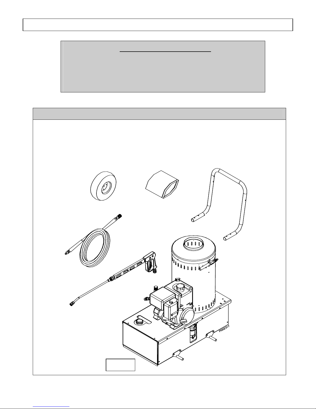
Step 1. Unpacking & Delivery Inspection
Find and separate the components identified in Figure 2 – Overview of Pressure Washer
Components and Figure 3 – Hardware Bag. Inspect the power washer immediately after you
receive delivery for missing parts and damage.
• If you have missing components, contact Product Support at 1-800-270-0810.
• If you have damaged components, contact the freight company that delivered the unit and file
a claim.
Wheel
Qty-4
High Pressure Hose
Spray Gun
Qty-1
Figure 2
Hardware Bag
Handle
Qty-1
Qty-1
Pressure Washer
10
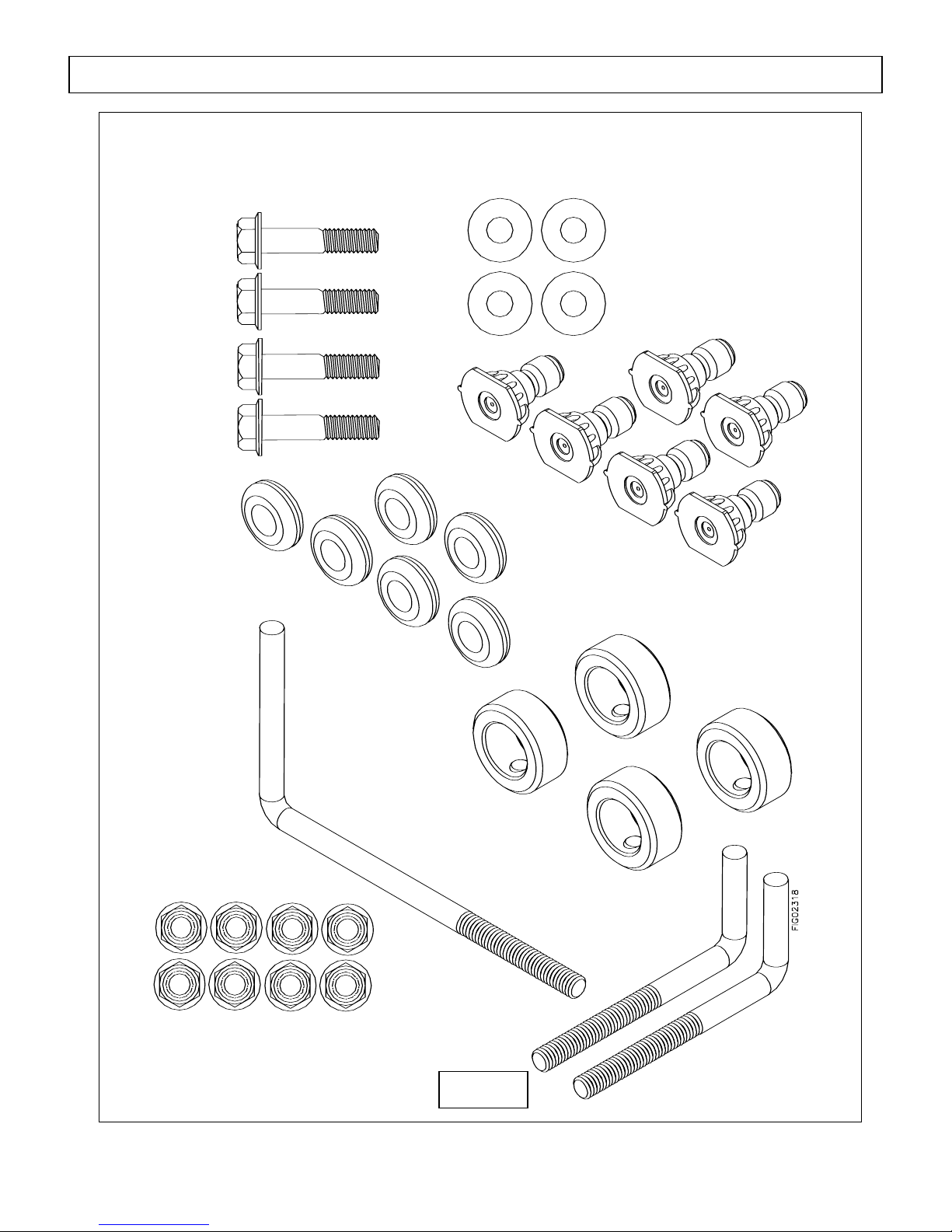
Grommets
Qty-6
Part # 35198
Hose Hook
Qty-1
Part # 38510
5/16-18 Flange Nut
Assembly and Initial Set-Up
5/16-18 x 2” Flange Bolt
Qty-4
Part # 82018
Qty-8
Part # 82019
5/16 Flat Washer
Qty-4
Part # 82021
Figure 3
Nozzles
Qty-6
Part # 38531 & 778198
Wheel Retainers
Qty-4
Part # 305200
Gun Hook
Qty-2
Part # 38509
11
Assembly and Initial Set-Up
N
g
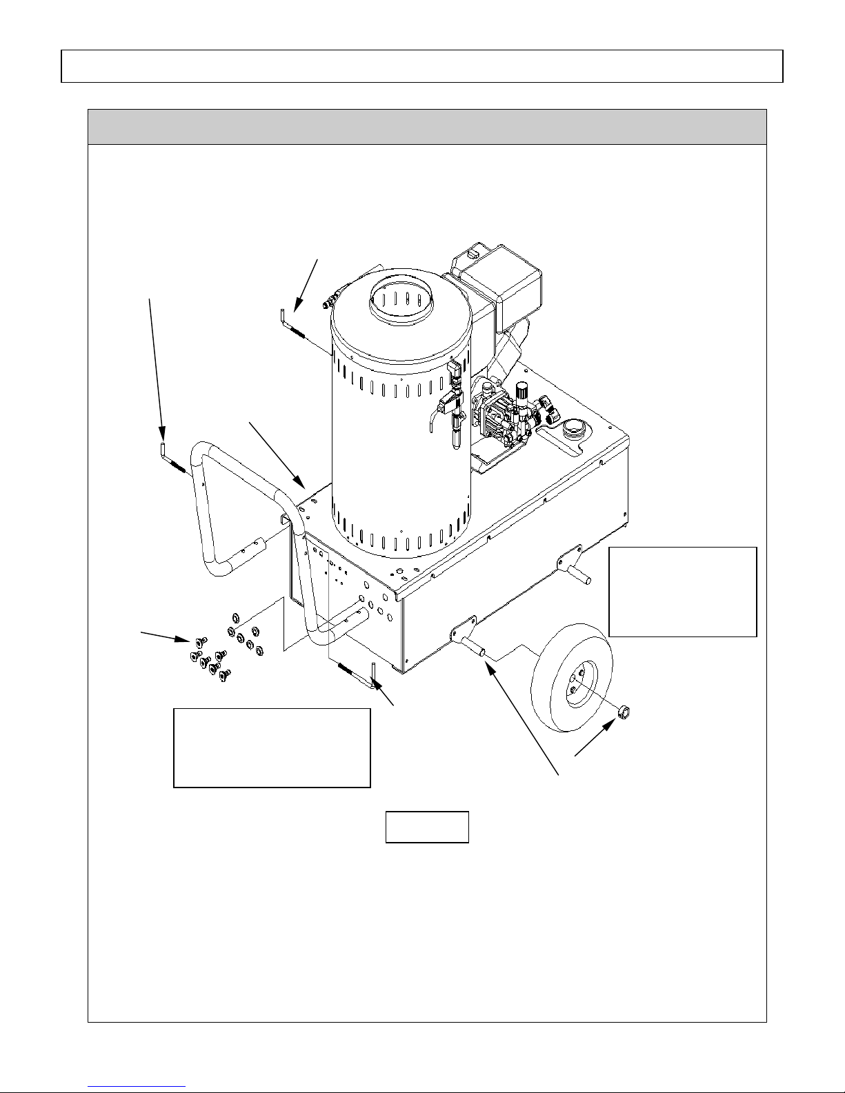
Step 2. Assembly
You must assemble your pressure washer before it can be used. Refer to Figure 4 and follow the
steps listed below:
Install One (1) Gun
Hooks into Left Side of
Handle using Two (2)
5/16-18 Flan
e Nuts
Install Four (4)
Flange Bolts through
Base and Handle and
Secure with Four (4)
5/16-18 Flange Nuts
and Washers
Install Grommets and
ozzles into Holes in
Control Panel
FIG02320
Note: It is Recommended that
Two People Lift this Unit
While a Third Slides the
Wheels onto the Axle
Install One (1) Gun Hook
on Left side of Base
Install Hose
Hook into Right
Side of Handle
using a (2) 5/1618 Flange Nuts
Figure 4
Install
Wheel onto
Axle
Lift Back of Unit by
Handle to Install Rear
Wheels, then Lift
Front of Unit to Install
Front Wheels
Fasten Wheel with
Retainer using a hex
wrench
Step 1. Install handle with four (4) 5/16-18 x 2” Flange Bolts through Base and Handle and
secure with four (4) 5/16-18 Flange Nuts and Washers.
Step 2. Install one (1) Gun Hook into the left side of the Handle using two (2) 5/16-18 Flange
Nuts.
Step 3. Install Hose Hook into right side of Handle using two (2) 5/16-18 Flange Nuts.
12
Assembly and Initial Set-Up
Step 4. Install one (1) Gun Hook on left side of pressure washer base (below engine). Screw
hook directly into base until tight.
Step 5. Install Grommets and Nozzles into Holes in Control Panel.
Step 6. Install Wheels:
WARNING
serious injury if it rolls out of control or tips over. Always use at least two
people or a mechanical assist to lift the unit while a third person slides the
wheels onto the axles.
: The pressure washer is heavy. It can crush and cause
a. Rear Wheels
Have two people lift the back of the pressure washer while a third person slides the
wheels onto the Rear Axle. Fasten each wheel with a wheel retainer using a hex
wrench.
b. Front Wheels
Have two people lift the front of the pressure washer by the handle while a third person
slides the wheels onto the Front Axle. Fasten each wheel with a wheel retainer using a
hex wrench.
Step 7. Use a mechanical assist or two people to lift the assembled Pressure Washer off of the
pallet.
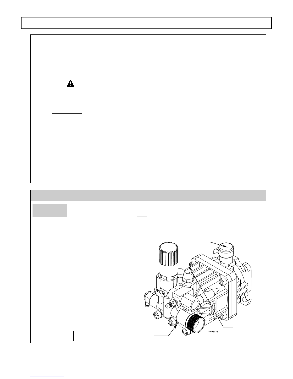
Step 3. Initial Pump & Engine Preparation
Prepare
Water Pump
Verify pump oil level.
Note: The pump is shipped with oil.
1. Verify that oil level is half way up the sight glass.
2. If oil level is low, fill using Universal Tractor Transmission Oil or Mobil 1
Synthetic 15W-50 oil.
Oil Cap
3. Use Replace fill cap.
Oil Sight
Figure 5
Drain Plug
13
Glass
Assembly and Initial Set-Up
N
y
y
y
Prepare
Engine
Fill the engine with oil.
Note: The engine is shipped without oil.
Refer to the Engine Manual to locate oil-fill port and for instructions on filling.
Use the oil grade and quantity specified in the Engine Manual.
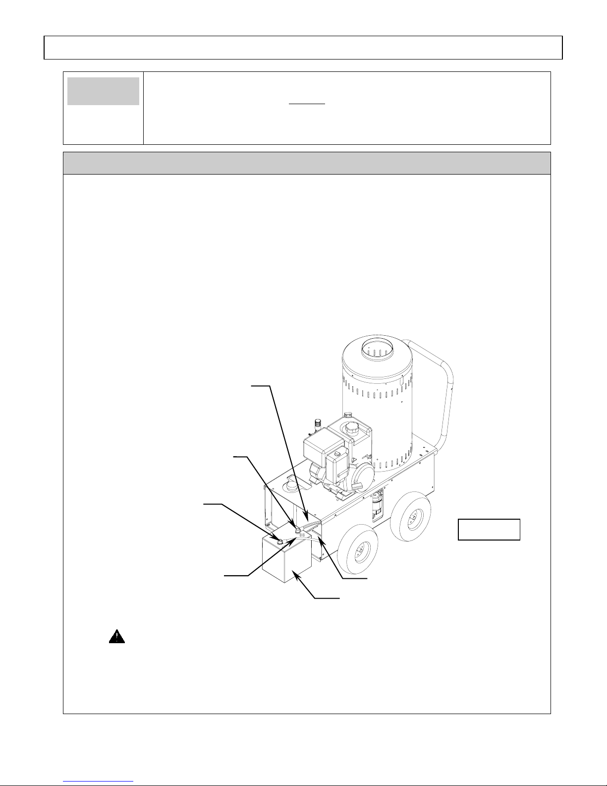
Step 4. Battery Installation
Install a 12-volt standard lawn and garden battery (Group U1-7) with a minimum 18 amphour rating.
CAUTION: A battery must be installed before starting the engine or damage to the engine
voltage regulator will result.
The battery is to be supplied by the customer and should be installed in the protective battery
compartment located near the engine. The inside dimensions of the battery compartment are 111/8”L x 7-3/4”W x 10-1/8”H.
The battery compartment is shown in Figure 6 below. To install the battery, first remove the end
cap to gain access to the battery compartment. Follow the steps below for connecting and
disconnecting the battery.
Positive Batter
egative Batter
Terminal (-)
Black Batter
Red Battery
Terminal (+)
Cable
Cable
Battery Compartment
Battery (NOT INCLUDED)
12VDC 18Ah Minimum
Figure 6
WARNING: Battery Hazards
Batteries are hazardous because they contain caustic acid, can emit explosive gases, and can
cause electric shock. Caution must be exercised when making connections to a battery to
avoid shock and contact with the acid, and to prevent any sparking that could lead to an
explosion. ALWAYS follow the general battery safety rules and instructions listed below.
14
Assembly and Initial Set-Up
General
Battery
Safety Rules
Connecting
the battery
Disconnecting
the battery
• ALWAYS use eye protection and protective clothing when handling
batteries.
• NEVER smoke or work near sparks or other sources of ignition.
• NEVER touch both battery terminals at the same time with your hand or any
non-insulated tools.
• If battery acid contacts skin or clothing, flush immediately with water and
neutralize with baking soda.
Always connect the cables in the following sequence to avoid possible shock:
1. Find the battery cables located inside the battery compartment.
2. Connect the red cable to the positive (+) terminal of the battery.
3. Then connect the black cable to the negative (-) terminal of the battery.
4. Reinstall the battery compartment end cap before using the pressure washer.
Always disconnect cables in the following sequence to avoid possible shock.
1. First, disconnect the black cable from the negative (-) terminal of the
battery.
2. Next, disconnect the red cable from the positive (+) terminal of the battery.
3. Remove the battery from the battery compartment.
4. Reinstall the battery compartment end cap.
15
Moving and Handling
The pressures washer is heavy. It can crush and cause serious injury if it rolls out of
control or tips over. Follow the instructions below for safely moving the pressure
washer.
WARNING
Moving and Handling
FIG02237
Figure 7
Lift Here
Handle
Moving your
pressure washer
around
Elevating or
lowering your
pressure washer
1. Use the handle to manually move the pressure washer.
2. To turn, lift slightly on the handle and pivot the pressure washer on its
front wheels.
3. Block wheels to prevent inadvertent movement.
To reduce risk of injury, do not attempt to lift the pressure washer. Use a
shallow ramp to raise or lower the pressure washer to a different elevation.
16
Before Each Use
Follow the steps below prior to each use of the pressure washer.
Steps to Follow Before Each Use
Step 1. Check Equipment
Step 2. Add Fuel(s)
Step 3. Select Suitable Worksite
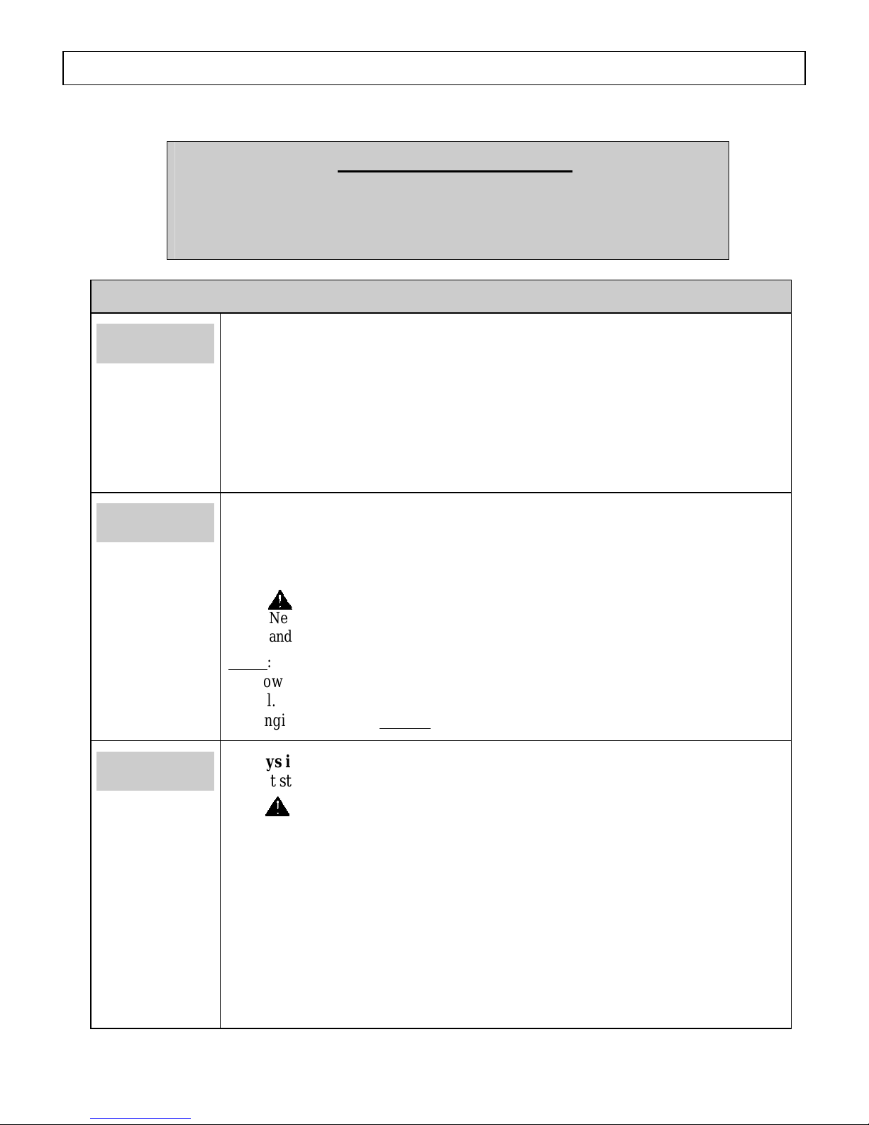
Step 1. Check Equipment
Check/add
pump oil
Check/add
engine oil
Check/add pump oil.
Caution: Never run the pump without sufficient lubrication!
1. Check oil level. Verify that oil level is half way up the sight glass (or at the
indicator line on the dip stick).
2. If oil level is low, fill using Universal Tractor Transmission Oil or Mobil 1
Synthetic 15W-50 oil.
3. Replace fill cap.
Check the engine oil level and add oil as needed.
Use the recommended oil type for your engine and expected ambient conditions.
(See engine Owner’s Manual for oil type and capacity, and more detailed oil
check/fill instructions.)
WARNING: Burn hazard
Never open oil port while engine is running. Hot oil can spray over face
and body.
˙
Notes:
o Low oil shutdown feature prevents the engine from starting without sufficient
oil.
o Engine is shipped without
oil. You must add oil before first use.
Inspect spray
system
Always inspect spray system for damage and leaks before each use.
Do not start pressure washer until all needed repairs have been completed.
WARNING: High pressure fluid injection hazard
High-pressure fluid discharge from leaks (even pin-sized) or ruptured
components can pierce skin and inject fluid into the body. Injection
injury can result in blood poisoning and/or severe tissue damage leading
to infection, gangrene, and possibly amputation.
• Never use a finger or skin to check for leaks.
• Never operate machine with damaged or missing hoses/parts.
• Never attempt to repair a high-pressure hose or component – Always
replace it with a part that is rated at or above the pressure rating of this
machine.
17
Before Each Use
1) Check hoses, fittings, wand, trigger gun and connections for signs of wear,
cracks, looseness, or leaks. Replace as required.
2) Check and clean the nozzle orifice.
3) Clean inlet filter. (See Maintenance instructions)
Inspect fuel
system
Perform other
scheduled
maintenance as
needed
Always inspect (engine and burner) fuel systems & check for leaks
BEFORE starting pressure washer.
Do not start pressure washer until all needed repairs have been completed.
WARNING: Fuel leak hazard
Gasoline and burner fuels are highly explosive and fuel leaks can result in
fire or explosions. You can be burned and seriously injured if the fuel
system is not properly hooked up or there is a fuel leak when you start the
engine.
Inspect the entire fuel system. Look for:
• signs of leaks or deterioration,
• chafed or spongy fuel hose,
• loose connections,
• loose or missing fuel hose clamps,
• damaged gasoline tank, or
• defective gasoline shut-off valve.
Make sure that any other regular maintenance has been performed as
prescribed in this manual in the “Maintenance & Repair” section.
1. Refer to the engine owner’s manual for engine maintenance instructions.
2. Make sure battery is charged. Charge as needed according to your battery
manufacturer’s instructions.
Step 2. Add Fuel(s)
WARNING: Fuel fire/explosion hazard
Gasoline is highly flammable and explosive. Burner fuels are combustible at warm
temperatures. Heat, sparks, and flames can ignite fuel vapors, which can become widespread
during fueling. A flash fire and/or explosion could result and cause serious injury or death.
Always use extreme care when handling fuels. Carefully follow all instructions to avoid the
following conditions which could result in fuel ignition:
• gas vapor collection inside enclosures
• static electric sparks
• sparks from electric wiring, batteries, or running engines
• sources of heat (such as a hot engine, burner or exhaust)
• open flames, including pilot lights
Always follow these general safety rules when fueling:
1) Turn pressure washer off and allow to cool for at least two minutes before removing any fuel cap.
Note: A running or still-hot engine or burner is hot enough to ignite fuel.
18
Before Each Use
2) Fill fuel tank OUTDOORS – never indoors. Fuel vapors can ignite if they collect inside an
enclosure and explosion can result.
3) Stay away from all sources of heat, sparks, and flames. Do not smoke.
4) Never pump fuel directly into the gas tank or burner at a gas station – it could cause a static
electric spark. Follow these steps to avoid static electric sparking during fueling:
• Use an approved portable container to transfer fuel to the pressure washer’s
tank. (A portable container made of metal or conductive plastic is preferred
because it dissipates charge to ground more readily.)
• Always place container on the ground to be filled. Never fill the portable gas
container while it is sitting inside a vehicle, trailer, trunk, or pick-up truck
bed.
• Dissipate static charge from your body before beginning the fueling process
by touching a grounded metal object at a safe distance from fuel sources.
• Keep nozzle in contact with container while filling. Do not use a nozzle lock-
5) Clean up fuel spills /splashes immediately.
open device.
• If possible, move the pressure washer away from spilled fuel on the ground.
• Wipe up spilled fuel and wait 5 minutes for excess fuel to evaporate before starting
engine.
• Fuel soaked rags are flammable and should be disposed of properly.
• If fuel is spilled on your skin or clothes, change clothes and wash skin immediately.
Fill engine fuel
tank
Fill burner fuel
tank
(if planning to
use heated
water)
Check the gasoline tank level. If needed, fill tank with fresh unleaded
gasoline from a portable container:
1) Remove engine gas cap.
2) Add gasoline through the fill opening:
- Use only an UL-approved portable gasoline container to transfer the
gasoline to engine’s tank.
- Do NOT overfill the gasoline tank. Allow at least 1/2” of empty space
below the fill neck to allow for fuel expansion.
3) Replace gas cap securely before starting engine.
4) Store extra gasoline in a cool, dry place in an UL-approved, tightly sealed
container.
If you are planning to use heated water, fill burner fuel tank with #1 or #2
diesel, B5 or lower biodiesel, kerosene, or fuel oil.
1) Remove burner fuel cap.
2) Add fuel through the fill opening. Do not overfill. Allow at least 1/2” of
empty space below fill neck to allow for fuel expansion.
3) Replace fuel cap securely before starting engine.
4) Wipe any excess fuel from unit before starting
19
 Loading...