

Page 1

Contents
List of Figures . . . . . . . . . . . . . . . . . . . . . . . . . . . . . . . . . . . . . . . . . . . . . . . . . . . . . . . . . . . . . . . . . . . . . . . . . . vii
List of Tables. . . . . . . . . . . . . . . . . . . . . . . . . . . . . . . . . . . . . . . . . . . . . . . . . . . . . . . . . . . . . . . . . . . . . . . . . . . ix
List of Screens. . . . . . . . . . . . . . . . . . . . . . . . . . . . . . . . . . . . . . . . . . . . . . . . . . . . . . . . . . . . . . . . . . . . . . . . . . xi
Chapter 1: Quick Start . . . . . . . . . . . . . . . . . . . . . . . . . . . . . . . . . . . . . . . . . . . . . . . . . . . . . . . . . . . . . . . . . 1-1
Welcome. . . . . . . . . . . . . . . . . . . . . . . . . . . . . . . . . . . . . . . . . . . . . . . . . . . . . . . . . . . . . . . . .1-2
Technical support . . . . . . . . . . . . . . . . . . . . . . . . . . . . . . . . . . . . . . . . . . . . . . . . . . . . . . . . .1-7
Turning the system on. . . . . . . . . . . . . . . . . . . . . . . . . . . . . . . . . . . . . . . . . . . . . . . . . . . . .1-9
Turning the system off. . . . . . . . . . . . . . . . . . . . . . . . . . . . . . . . . . . . . . . . . . . . . . . . . . . .1-13
Basic navigation terminology . . . . . . . . . . . . . . . . . . . . . . . . . . . . . . . . . . . . . . . . . . . . . .1-14
Highlight One: Basic navigation terms . . . . . . . . . . . . . . . . . . . . . . . . . . . . . . . . . . . . . .1-15
Introducing the function keys . . . . . . . . . . . . . . . . . . . . . . . . . . . . . . . . . . . . . . . . . . . . .1-16
Using the chart-view screens . . . . . . . . . . . . . . . . . . . . . . . . . . . . . . . . . . . . . . . . . . . . . .1-17
Navigating to a point . . . . . . . . . . . . . . . . . . . . . . . . . . . . . . . . . . . . . . . . . . . . . . . . . . . . .1-24
Reading and clearing alarm messages. . . . . . . . . . . . . . . . . . . . . . . . . . . . . . . . . . . . . . .1-30
Chapter 2: Introducing the 961/962 . . . . . . . . . . . . . . . . . . . . . . . . . . . . . . . . . . . . . . . . . . . . . . . . . . . 2-1
System overview . . . . . . . . . . . . . . . . . . . . . . . . . . . . . . . . . . . . . . . . . . . . . . . . . . . . . . . . . .2-2
Introducing the controls . . . . . . . . . . . . . . . . . . . . . . . . . . . . . . . . . . . . . . . . . . . . . . . . . . .2-6
Entering data . . . . . . . . . . . . . . . . . . . . . . . . . . . . . . . . . . . . . . . . . . . . . . . . . . . . . . . . . . . . . 2-7
Caring for the system . . . . . . . . . . . . . . . . . . . . . . . . . . . . . . . . . . . . . . . . . . . . . . . . . . . . . .2-8
About interfacing the system . . . . . . . . . . . . . . . . . . . . . . . . . . . . . . . . . . . . . . . . . . . . . .2-10
Introducing GPS and DGPS . . . . . . . . . . . . . . . . . . . . . . . . . . . . . . . . . . . . . . . . . . . . . . . .2-11
Chapter 3: Using the Controls . . . . . . . . . . . . . . . . . . . . . . . . . . . . . . . . . . . . . . . . . . . . . . . . . . . . . . . . . 3-1
More navigation terminology . . . . . . . . . . . . . . . . . . . . . . . . . . . . . . . . . . . . . . . . . . . . . . .3-2
Highlight Two: More navigation terms. . . . . . . . . . . . . . . . . . . . . . . . . . . . . . . . . . . . . . .3-2
PWR key . . . . . . . . . . . . . . . . . . . . . . . . . . . . . . . . . . . . . . . . . . . . . . . . . . . . . . . . . . . . . . . . . 3-3
Function keys . . . . . . . . . . . . . . . . . . . . . . . . . . . . . . . . . . . . . . . . . . . . . . . . . . . . . . . . . . . .3-5
Brightness key . . . . . . . . . . . . . . . . . . . . . . . . . . . . . . . . . . . . . . . . . . . . . . . . . . . . . . . . . . .3-27
SAVE key. . . . . . . . . . . . . . . . . . . . . . . . . . . . . . . . . . . . . . . . . . . . . . . . . . . . . . . . . . . . . . . .3-28
MOB key . . . . . . . . . . . . . . . . . . . . . . . . . . . . . . . . . . . . . . . . . . . . . . . . . . . . . . . . . . . . . . . .3-28
IN and OUT keys. . . . . . . . . . . . . . . . . . . . . . . . . . . . . . . . . . . . . . . . . . . . . . . . . . . . . . . . .3-31
Cursor pad . . . . . . . . . . . . . . . . . . . . . . . . . . . . . . . . . . . . . . . . . . . . . . . . . . . . . . . . . . . . . .3-31
Arrow keys . . . . . . . . . . . . . . . . . . . . . . . . . . . . . . . . . . . . . . . . . . . . . . . . . . . . . . . . . . . . . .3-32
Menu keys . . . . . . . . . . . . . . . . . . . . . . . . . . . . . . . . . . . . . . . . . . . . . . . . . . . . . . . . . . . . . .3-33
961/962 Operations and Reference Manual, Rev. A Page iii
Page 2

Chapter 4: Understanding the Chart Screen . . . . . . . . . . . . . . . . . . . . . . . . . . . . . . . . . . . . . . . . . . . 4-1
Understanding electronic charts . . . . . . . . . . . . . . . . . . . . . . . . . . . . . . . . . . . . . . . . . . . .4-2
Understanding the chart screen . . . . . . . . . . . . . . . . . . . . . . . . . . . . . . . . . . . . . . . . . . . . .4-2
Displaying your vessel’s position on a chart . . . . . . . . . . . . . . . . . . . . . . . . . . . . . . . . . .4-4
Functions performed at the chart screen . . . . . . . . . . . . . . . . . . . . . . . . . . . . . . . . . . . . .4-4
Using the cursor on the chart screen . . . . . . . . . . . . . . . . . . . . . . . . . . . . . . . . . . . . . . .4-17
Chapter 5: Understanding Position Coordinates . . . . . . . . . . . . . . . . . . . . . . . . . . . . . . . . . . . . . . . 5-1
Using GPS to determine position . . . . . . . . . . . . . . . . . . . . . . . . . . . . . . . . . . . . . . . . . . . .5-2
Using DGPS to determine position. . . . . . . . . . . . . . . . . . . . . . . . . . . . . . . . . . . . . . . . . . . 5-4
Understanding Loran-C . . . . . . . . . . . . . . . . . . . . . . . . . . . . . . . . . . . . . . . . . . . . . . . . . . . .5-7
Using Phantom loran to determine position . . . . . . . . . . . . . . . . . . . . . . . . . . . . . . . . .5-10
Chapter 6: Creating Waypoints . . . . . . . . . . . . . . . . . . . . . . . . . . . . . . . . . . . . . . . . . . . . . . . . . . . . . . . . 6-1
Introducing waypoints . . . . . . . . . . . . . . . . . . . . . . . . . . . . . . . . . . . . . . . . . . . . . . . . . . . . .6-2
Displaying waypoints . . . . . . . . . . . . . . . . . . . . . . . . . . . . . . . . . . . . . . . . . . . . . . . . . . . . . .6-3
Sorting the list of waypoints . . . . . . . . . . . . . . . . . . . . . . . . . . . . . . . . . . . . . . . . . . . . . . . .6-6
Searching for a waypoint . . . . . . . . . . . . . . . . . . . . . . . . . . . . . . . . . . . . . . . . . . . . . . . . . . .6-7
Creating a new waypoint . . . . . . . . . . . . . . . . . . . . . . . . . . . . . . . . . . . . . . . . . . . . . . . . . . .6-8
Editing a waypoint . . . . . . . . . . . . . . . . . . . . . . . . . . . . . . . . . . . . . . . . . . . . . . . . . . . . . . .6-14
Erasing a waypoint . . . . . . . . . . . . . . . . . . . . . . . . . . . . . . . . . . . . . . . . . . . . . . . . . . . . . . .6-16
Changing the display of coordinates. . . . . . . . . . . . . . . . . . . . . . . . . . . . . . . . . . . . . . . .6-16
Chapter 7: Creating Avoidance Points . . . . . . . . . . . . . . . . . . . . . . . . . . . . . . . . . . . . . . . . . . . . . . . . . 7-1
Introducing avoidance points . . . . . . . . . . . . . . . . . . . . . . . . . . . . . . . . . . . . . . . . . . . . . . . 7-2
Displaying avoidance points . . . . . . . . . . . . . . . . . . . . . . . . . . . . . . . . . . . . . . . . . . . . . . . .7-3
Sorting the list of avoidance points . . . . . . . . . . . . . . . . . . . . . . . . . . . . . . . . . . . . . . . . . .7-7
Searching for an avoidance point. . . . . . . . . . . . . . . . . . . . . . . . . . . . . . . . . . . . . . . . . . . .7-8
Creating a new avoidance point. . . . . . . . . . . . . . . . . . . . . . . . . . . . . . . . . . . . . . . . . . . . .7-9
Editing an avoidance point . . . . . . . . . . . . . . . . . . . . . . . . . . . . . . . . . . . . . . . . . . . . . . . .7-13
Erasing an avoidance point . . . . . . . . . . . . . . . . . . . . . . . . . . . . . . . . . . . . . . . . . . . . . . . .7-14
Changing the display of coordinates. . . . . . . . . . . . . . . . . . . . . . . . . . . . . . . . . . . . . . . .7-15
Chapter 8: Creating Routes. . . . . . . . . . . . . . . . . . . . . . . . . . . . . . . . . . . . . . . . . . . . . . . . . . . . . . . . . . . . 8-1
Introducing routes . . . . . . . . . . . . . . . . . . . . . . . . . . . . . . . . . . . . . . . . . . . . . . . . . . . . . . . . 8-2
Displaying routes . . . . . . . . . . . . . . . . . . . . . . . . . . . . . . . . . . . . . . . . . . . . . . . . . . . . . . . . .8-3
Sorting the list of routes. . . . . . . . . . . . . . . . . . . . . . . . . . . . . . . . . . . . . . . . . . . . . . . . . . . .8-6
Searching for a route . . . . . . . . . . . . . . . . . . . . . . . . . . . . . . . . . . . . . . . . . . . . . . . . . . . . . .8-7
Creating a new route . . . . . . . . . . . . . . . . . . . . . . . . . . . . . . . . . . . . . . . . . . . . . . . . . . . . . .8-8
Editing a route . . . . . . . . . . . . . . . . . . . . . . . . . . . . . . . . . . . . . . . . . . . . . . . . . . . . . . . . . . .8-17
Erasing a route. . . . . . . . . . . . . . . . . . . . . . . . . . . . . . . . . . . . . . . . . . . . . . . . . . . . . . . . . . .8-24
Page iv 961/962 Operations and Reference Manual, Rev. A
Page 3

Chapter 9: Creating Tracks . . . . . . . . . . . . . . . . . . . . . . . . . . . . . . . . . . . . . . . . . . . . . . . . . . . . . . . . . . . . 9-1
Introducing tracks. . . . . . . . . . . . . . . . . . . . . . . . . . . . . . . . . . . . . . . . . . . . . . . . . . . . . . . . . 9-2
Displaying tracks. . . . . . . . . . . . . . . . . . . . . . . . . . . . . . . . . . . . . . . . . . . . . . . . . . . . . . . . . .9-3
Sorting the list of tracks . . . . . . . . . . . . . . . . . . . . . . . . . . . . . . . . . . . . . . . . . . . . . . . . . . . .9-6
Creating a new track . . . . . . . . . . . . . . . . . . . . . . . . . . . . . . . . . . . . . . . . . . . . . . . . . . . . . .9-7
Editing a track . . . . . . . . . . . . . . . . . . . . . . . . . . . . . . . . . . . . . . . . . . . . . . . . . . . . . . . . . . .9-10
Erasing a track . . . . . . . . . . . . . . . . . . . . . . . . . . . . . . . . . . . . . . . . . . . . . . . . . . . . . . . . . . .9-12
Chapter 10: Waypoint and Route Navigation . . . . . . . . . . . . . . . . . . . . . . . . . . . . . . . . . . . . . . . . . 10-1
Steering to a waypoint . . . . . . . . . . . . . . . . . . . . . . . . . . . . . . . . . . . . . . . . . . . . . . . . . . . .10-2
Navigating from the routes screen . . . . . . . . . . . . . . . . . . . . . . . . . . . . . . . . . . . . . . . . .10-6
Navigating from the chart screen . . . . . . . . . . . . . . . . . . . . . . . . . . . . . . . . . . . . . . . . 10-10
Navigating from the waypoints screen . . . . . . . . . . . . . . . . . . . . . . . . . . . . . . . . . . . . 10-17
Restarting the track . . . . . . . . . . . . . . . . . . . . . . . . . . . . . . . . . . . . . . . . . . . . . . . . . . . . 10-19
Chapter 11: Using the Trip Function . . . . . . . . . . . . . . . . . . . . . . . . . . . . . . . . . . . . . . . . . . . . . . . . . . 11-1
Introducing the trip function . . . . . . . . . . . . . . . . . . . . . . . . . . . . . . . . . . . . . . . . . . . . . .11-2
Displaying the trip . . . . . . . . . . . . . . . . . . . . . . . . . . . . . . . . . . . . . . . . . . . . . . . . . . . . . . .11-3
Changing the trip . . . . . . . . . . . . . . . . . . . . . . . . . . . . . . . . . . . . . . . . . . . . . . . . . . . . . . . .11-5
Saving the trip as a route. . . . . . . . . . . . . . . . . . . . . . . . . . . . . . . . . . . . . . . . . . . . . . . . 11-11
Erasing the trip . . . . . . . . . . . . . . . . . . . . . . . . . . . . . . . . . . . . . . . . . . . . . . . . . . . . . . . . 11-12
Restarting the track at the trip screen . . . . . . . . . . . . . . . . . . . . . . . . . . . . . . . . . . . . . 11-14
Stopping navigation . . . . . . . . . . . . . . . . . . . . . . . . . . . . . . . . . . . . . . . . . . . . . . . . . . . . 11-15
Chapter 12: Alarms, TideTrack, Currents, and Echo Sounding. . . . . . . . . . . . . . . . . . . . . . . . . 12-1
Understanding alarms . . . . . . . . . . . . . . . . . . . . . . . . . . . . . . . . . . . . . . . . . . . . . . . . . . . .12-2
Understanding the TideTrack function. . . . . . . . . . . . . . . . . . . . . . . . . . . . . . . . . . . . 12-11
Understanding the currents function . . . . . . . . . . . . . . . . . . . . . . . . . . . . . . . . . . . . . 12-15
Adding the echo sounder overlay . . . . . . . . . . . . . . . . . . . . . . . . . . . . . . . . . . . . . . . . 12-19
Chapter 13: Customizing Setup Functions . . . . . . . . . . . . . . . . . . . . . . . . . . . . . . . . . . . . . . . . . . . . 13-1
Changing the display setup. . . . . . . . . . . . . . . . . . . . . . . . . . . . . . . . . . . . . . . . . . . . . . . .13-2
Changing navigation setup . . . . . . . . . . . . . . . . . . . . . . . . . . . . . . . . . . . . . . . . . . . . . . 13-10
Changing the chart setup . . . . . . . . . . . . . . . . . . . . . . . . . . . . . . . . . . . . . . . . . . . . . . . 13-24
Loading, updating, and deleting charts. . . . . . . . . . . . . . . . . . . . . . . . . . . . . . . . . . . . 13-35
Using demo mode . . . . . . . . . . . . . . . . . . . . . . . . . . . . . . . . . . . . . . . . . . . . . . . . . . . . . . 13-69
Viewing the time information screen . . . . . . . . . . . . . . . . . . . . . . . . . . . . . . . . . . . . . 13-72
Chapter 14: Service and Maintenance Functions . . . . . . . . . . . . . . . . . . . . . . . . . . . . . . . . . . . . . 14-1
Service functions . . . . . . . . . . . . . . . . . . . . . . . . . . . . . . . . . . . . . . . . . . . . . . . . . . . . . . . . .14-2
Maintenance functions . . . . . . . . . . . . . . . . . . . . . . . . . . . . . . . . . . . . . . . . . . . . . . . . . 14-17
961/962 Operations and Reference Manual, Rev. A Page v
Page 4

961/962 Features and Specifications . . . . . . . . . . . . . . . . . . . . . . . . . . . . . . . . . . . . . . . . . . . . . . . . A-1
Navigation . . . . . . . . . . . . . . . . . . . . . . . . . . . . . . . . . . . . . . . . . . . . . . . . . . . . . . . . . . . . . . A-1
Position data . . . . . . . . . . . . . . . . . . . . . . . . . . . . . . . . . . . . . . . . . . . . . . . . . . . . . . . . . . . . A-2
Steer screens . . . . . . . . . . . . . . . . . . . . . . . . . . . . . . . . . . . . . . . . . . . . . . . . . . . . . . . . . . . . A-2
Waypoint and route management . . . . . . . . . . . . . . . . . . . . . . . . . . . . . . . . . . . . . . . . . . A-2
Waypoint navigation . . . . . . . . . . . . . . . . . . . . . . . . . . . . . . . . . . . . . . . . . . . . . . . . . . . . . A-3
Trip functions . . . . . . . . . . . . . . . . . . . . . . . . . . . . . . . . . . . . . . . . . . . . . . . . . . . . . . . . . . . A-3
Echo sounder . . . . . . . . . . . . . . . . . . . . . . . . . . . . . . . . . . . . . . . . . . . . . . . . . . . . . . . . . . . . A-4
Miscellaneous functions . . . . . . . . . . . . . . . . . . . . . . . . . . . . . . . . . . . . . . . . . . . . . . . . . . A-4
GPS receiver . . . . . . . . . . . . . . . . . . . . . . . . . . . . . . . . . . . . . . . . . . . . . . . . . . . . . . . . . . . . . A-4
DGPS receiver (961XD/962XD). . . . . . . . . . . . . . . . . . . . . . . . . . . . . . . . . . . . . . . . . . . . . A-5
Interfacing . . . . . . . . . . . . . . . . . . . . . . . . . . . . . . . . . . . . . . . . . . . . . . . . . . . . . . . . . . . . . . A-6
Physical features . . . . . . . . . . . . . . . . . . . . . . . . . . . . . . . . . . . . . . . . . . . . . . . . . . . . . . . . . A-6
Options . . . . . . . . . . . . . . . . . . . . . . . . . . . . . . . . . . . . . . . . . . . . . . . . . . . . . . . . . . . . . . . . . A-7
Warranty. . . . . . . . . . . . . . . . . . . . . . . . . . . . . . . . . . . . . . . . . . . . . . . . . . . . . . . . . . . . . . . . A-8
GPS Antenna . . . . . . . . . . . . . . . . . . . . . . . . . . . . . . . . . . . . . . . . . . . . . . . . . . . . . . . . . . . . A-8
GPS/DGPS Combination Antenna . . . . . . . . . . . . . . . . . . . . . . . . . . . . . . . . . . . . . . . . . . A-8
Glossary . . . . . . . . . . . . . . . . . . . . . . . . . . . . . . . . . . . . . . . . . . . . . . . . . . . . . . . . . . . . . . . . . . . . . . . . . . . . . G-1
Index . . . . . . . . . . . . . . . . . . . . . . . . . . . . . . . . . . . . . . . . . . . . . . . . . . . . . . . . . . . . . . . . . . . . . . . . . . . . . . . . . I-1
Page vi 961/962 Operations and Reference Manual, Rev. A
Page 5

List of Figures
Figure 1: 961/962 function keys . . . . . . . . . . . . . . . . . . . . . . . . . . . . . . . . . . . . . . . . . . . . . .1-16
Figure 2: 961/962 controls . . . . . . . . . . . . . . . . . . . . . . . . . . . . . . . . . . . . . . . . . . . . . . . . . . . . 2-7
Figure 3: GPS satellites communicating with vessel . . . . . . . . . . . . . . . . . . . . . . . . . . . . .2-12
Figure 4: Position variances with uncorrected GPS . . . . . . . . . . . . . . . . . . . . . . . . . . . . . . .5-9
Figure 5: Restarting the desired track . . . . . . . . . . . . . . . . . . . . . . . . . . . . . . . . . . . . . . . 10-20
Figure 6: Passing a waypoint . . . . . . . . . . . . . . . . . . . . . . . . . . . . . . . . . . . . . . . . . . . . . . . 13-21
Figure 7: North-up orientation: vessel on northerly leg . . . . . . . . . . . . . . . . . . . . . . . . 13-31
Figure 8: North-up orientation: vessel on southeasterly leg . . . . . . . . . . . . . . . . . . . . 13-31
Figure 9: Course-up chart orientation . . . . . . . . . . . . . . . . . . . . . . . . . . . . . . . . . . . . . . . 13-32
961/962 Operations and Reference Manual, Rev. A Page vii
Page 6

Page viii 961/962 Operations and Reference Manual, Rev. A
Page 7

List of Tables
Table 1: Contacting Northstar . . . . . . . . . . . . . . . . . . . . . . . . . . . . . . . . . . . . . . . . . . . . . . . . . 1-7
Table 2: Noise-level meanings . . . . . . . . . . . . . . . . . . . . . . . . . . . . . . . . . . . . . . . . . . . . . . . . . 5-5
Table 3: DGPS status messages. . . . . . . . . . . . . . . . . . . . . . . . . . . . . . . . . . . . . . . . . . . . . . . . . 5-6
Table 4: Displaying waypoints . . . . . . . . . . . . . . . . . . . . . . . . . . . . . . . . . . . . . . . . . . . . . . . . . 6-3
Table 5: Displaying avoidance points . . . . . . . . . . . . . . . . . . . . . . . . . . . . . . . . . . . . . . . . . . . 7-3
Table 6: Displaying routes . . . . . . . . . . . . . . . . . . . . . . . . . . . . . . . . . . . . . . . . . . . . . . . . . . . . . 8-3
Table 7: Displaying tracks . . . . . . . . . . . . . . . . . . . . . . . . . . . . . . . . . . . . . . . . . . . . . . . . . . . . . 9-3
Table 8: 961/962 alarms. . . . . . . . . . . . . . . . . . . . . . . . . . . . . . . . . . . . . . . . . . . . . . . . . . . . . . 12-5
Table 9: Cross-track scale options . . . . . . . . . . . . . . . . . . . . . . . . . . . . . . . . . . . . . . . . . . . . . 13-4
Table 10: Datum list . . . . . . . . . . . . . . . . . . . . . . . . . . . . . . . . . . . . . . . . . . . . . . . . . . . . . . . . 13-12
Table 11: Reference ellipsoid constants . . . . . . . . . . . . . . . . . . . . . . . . . . . . . . . . . . . . . . . 13-19
Table 12: HCRF chart errors . . . . . . . . . . . . . . . . . . . . . . . . . . . . . . . . . . . . . . . . . . . . . . . . . 13-55
Table 13: Service checklist. . . . . . . . . . . . . . . . . . . . . . . . . . . . . . . . . . . . . . . . . . . . . . . . . . . 14-18
961/962 Operations and Reference Manual, Rev. A Page ix
Page 8

Page x 961/962 Operations and Reference Manual, Rev. A
Page 9

List of Screens
Initial startup screen . . . . . . . . . . . . . . . . . . . . . . . . . . . . . . . . . . . . . . . . . . . . . . . . . . . . . . . . . . .1-9
System test screen . . . . . . . . . . . . . . . . . . . . . . . . . . . . . . . . . . . . . . . . . . . . . . . . . . . . . . . . . . . .1-10
Owner’s message screen. . . . . . . . . . . . . . . . . . . . . . . . . . . . . . . . . . . . . . . . . . . . . . . . . . . . . . .1-11
Advisory message screen . . . . . . . . . . . . . . . . . . . . . . . . . . . . . . . . . . . . . . . . . . . . . . . . . . . . . .1-11
Power-off dialog box. . . . . . . . . . . . . . . . . . . . . . . . . . . . . . . . . . . . . . . . . . . . . . . . . . . . . . . . . .1-13
Chart view A . . . . . . . . . . . . . . . . . . . . . . . . . . . . . . . . . . . . . . . . . . . . . . . . . . . . . . . . . . . . . . . .1-18
Chart screen with info bars . . . . . . . . . . . . . . . . . . . . . . . . . . . . . . . . . . . . . . . . . . . . . . . . . . . .1-23
Chart screen with cursor location info bar. . . . . . . . . . . . . . . . . . . . . . . . . . . . . . . . . . . . . . .1-25
Selected cursor position dialog box . . . . . . . . . . . . . . . . . . . . . . . . . . . . . . . . . . . . . . . . . . . . .1-26
Chart screen with COORD waypoint. . . . . . . . . . . . . . . . . . . . . . . . . . . . . . . . . . . . . . . . . . . .1-27
Go to coordinates dialog box . . . . . . . . . . . . . . . . . . . . . . . . . . . . . . . . . . . . . . . . . . . . . . . . . .1-28
Chart screen with COORD waypoint. . . . . . . . . . . . . . . . . . . . . . . . . . . . . . . . . . . . . . . . . . . .1-29
Initial startup screen . . . . . . . . . . . . . . . . . . . . . . . . . . . . . . . . . . . . . . . . . . . . . . . . . . . . . . . . . . .3-3
Power-off dialog box. . . . . . . . . . . . . . . . . . . . . . . . . . . . . . . . . . . . . . . . . . . . . . . . . . . . . . . . . . .3-5
Chart screen with menu keys . . . . . . . . . . . . . . . . . . . . . . . . . . . . . . . . . . . . . . . . . . . . . . . . . . .3-7
Echo sounder screen. . . . . . . . . . . . . . . . . . . . . . . . . . . . . . . . . . . . . . . . . . . . . . . . . . . . . . . . . . .3-9
Alarms screen. . . . . . . . . . . . . . . . . . . . . . . . . . . . . . . . . . . . . . . . . . . . . . . . . . . . . . . . . . . . . . . .3-10
Chart-screen alarm message . . . . . . . . . . . . . . . . . . . . . . . . . . . . . . . . . . . . . . . . . . . . . . . . . . .3-11
Setup menu screen . . . . . . . . . . . . . . . . . . . . . . . . . . . . . . . . . . . . . . . . . . . . . . . . . . . . . . . . . . .3-12
Service menu screen . . . . . . . . . . . . . . . . . . . . . . . . . . . . . . . . . . . . . . . . . . . . . . . . . . . . . . . . . .3-14
Traditional steer screen . . . . . . . . . . . . . . . . . . . . . . . . . . . . . . . . . . . . . . . . . . . . . . . . . . . . . . .3-16
3-D steer screen . . . . . . . . . . . . . . . . . . . . . . . . . . . . . . . . . . . . . . . . . . . . . . . . . . . . . . . . . . . . . .3-17
Trip screen . . . . . . . . . . . . . . . . . . . . . . . . . . . . . . . . . . . . . . . . . . . . . . . . . . . . . . . . . . . . . . . . . .3-18
Waypoints screen . . . . . . . . . . . . . . . . . . . . . . . . . . . . . . . . . . . . . . . . . . . . . . . . . . . . . . . . . . . .3-20
Routes screen . . . . . . . . . . . . . . . . . . . . . . . . . . . . . . . . . . . . . . . . . . . . . . . . . . . . . . . . . . . . . . . .3-22
Tracks screen . . . . . . . . . . . . . . . . . . . . . . . . . . . . . . . . . . . . . . . . . . . . . . . . . . . . . . . . . . . . . . . .3-24
Avoidance points screen . . . . . . . . . . . . . . . . . . . . . . . . . . . . . . . . . . . . . . . . . . . . . . . . . . . . . .3-26
Man overboard dialog box. . . . . . . . . . . . . . . . . . . . . . . . . . . . . . . . . . . . . . . . . . . . . . . . . . . . .3-29
Chart screen with *MOB06* waypoint . . . . . . . . . . . . . . . . . . . . . . . . . . . . . . . . . . . . . . . . . . .3-30
Go to coordinates dialog box . . . . . . . . . . . . . . . . . . . . . . . . . . . . . . . . . . . . . . . . . . . . . . . . . . .4-6
Vessel-position charts screen . . . . . . . . . . . . . . . . . . . . . . . . . . . . . . . . . . . . . . . . . . . . . . . . . . .4-9
Cursor-position charts screen . . . . . . . . . . . . . . . . . . . . . . . . . . . . . . . . . . . . . . . . . . . . . . . . . . .4-9
Chart screen with tide stations and station coverage bar . . . . . . . . . . . . . . . . . . . . . . . . . .4-11
Chart screen with tide graph and tide station bar. . . . . . . . . . . . . . . . . . . . . . . . . . . . . . . . .4-12
961/962 Operations and Reference Manual, Rev. A Page xi
Page 10

Chart screen with current stations and station coverage bar . . . . . . . . . . . . . . . . . . . . . . .4-13
Chart screen with currents graph and current station bar . . . . . . . . . . . . . . . . . . . . . . . . .4-14
Chart view A with two info bars. . . . . . . . . . . . . . . . . . . . . . . . . . . . . . . . . . . . . . . . . . . . . . . .4-16
Chart view B with two info bars . . . . . . . . . . . . . . . . . . . . . . . . . . . . . . . . . . . . . . . . . . . . . . . .4-16
Chart screen with cursor info bar . . . . . . . . . . . . . . . . . . . . . . . . . . . . . . . . . . . . . . . . . . . . . .4-18
Chart screen with selected object . . . . . . . . . . . . . . . . . . . . . . . . . . . . . . . . . . . . . . . . . . . . . .4-19
Selected cursor position dialog box . . . . . . . . . . . . . . . . . . . . . . . . . . . . . . . . . . . . . . . . . . . . .4-21
Store as a waypoint dialog box . . . . . . . . . . . . . . . . . . . . . . . . . . . . . . . . . . . . . . . . . . . . . . . . .4-23
Store as a waypoint dialog box . . . . . . . . . . . . . . . . . . . . . . . . . . . . . . . . . . . . . . . . . . . . . . . . .4-25
Store as a waypoint (for on-chart route) dialog box . . . . . . . . . . . . . . . . . . . . . . . . . . . . . . .4-26
Selected route point dialog box . . . . . . . . . . . . . . . . . . . . . . . . . . . . . . . . . . . . . . . . . . . . . . . .4-28
Selected trip point dialog box . . . . . . . . . . . . . . . . . . . . . . . . . . . . . . . . . . . . . . . . . . . . . . . . . .4-29
Selected route point dialog box . . . . . . . . . . . . . . . . . . . . . . . . . . . . . . . . . . . . . . . . . . . . . . . .4-31
Selected trip leg dialog box . . . . . . . . . . . . . . . . . . . . . . . . . . . . . . . . . . . . . . . . . . . . . . . . . . . .4-32
Selected route leg dialog box . . . . . . . . . . . . . . . . . . . . . . . . . . . . . . . . . . . . . . . . . . . . . . . . . .4-33
Selected waypoint dialog box . . . . . . . . . . . . . . . . . . . . . . . . . . . . . . . . . . . . . . . . . . . . . . . . . .4-35
Edit selected waypoint dialog box . . . . . . . . . . . . . . . . . . . . . . . . . . . . . . . . . . . . . . . . . . . . . .4-35
Use selected waypoint dialog box . . . . . . . . . . . . . . . . . . . . . . . . . . . . . . . . . . . . . . . . . . . . . .4-36
Selected route point dialog box . . . . . . . . . . . . . . . . . . . . . . . . . . . . . . . . . . . . . . . . . . . . . . . .4-37
GPS satellite status screen . . . . . . . . . . . . . . . . . . . . . . . . . . . . . . . . . . . . . . . . . . . . . . . . . . . . . .5-3
Chart screen with waypoints. . . . . . . . . . . . . . . . . . . . . . . . . . . . . . . . . . . . . . . . . . . . . . . . . . . .6-4
Waypoints screen . . . . . . . . . . . . . . . . . . . . . . . . . . . . . . . . . . . . . . . . . . . . . . . . . . . . . . . . . . . . .6-5
Selected cursor position dialog box . . . . . . . . . . . . . . . . . . . . . . . . . . . . . . . . . . . . . . . . . . . . . . 6-9
Store as a waypoint dialog box . . . . . . . . . . . . . . . . . . . . . . . . . . . . . . . . . . . . . . . . . . . . . . . . .6-10
Vessel position dialog box . . . . . . . . . . . . . . . . . . . . . . . . . . . . . . . . . . . . . . . . . . . . . . . . . . . . .6-11
Chart screen with avoidance points. . . . . . . . . . . . . . . . . . . . . . . . . . . . . . . . . . . . . . . . . . . . . .7-4
3-D steer screen with avoidance points. . . . . . . . . . . . . . . . . . . . . . . . . . . . . . . . . . . . . . . . . . .7-5
Avoidance points screen . . . . . . . . . . . . . . . . . . . . . . . . . . . . . . . . . . . . . . . . . . . . . . . . . . . . . . .7-6
Selected cursor position dialog box . . . . . . . . . . . . . . . . . . . . . . . . . . . . . . . . . . . . . . . . . . . . .7-10
Store as a waypoint dialog box . . . . . . . . . . . . . . . . . . . . . . . . . . . . . . . . . . . . . . . . . . . . . . . . .7-10
Chart screen with displayed route . . . . . . . . . . . . . . . . . . . . . . . . . . . . . . . . . . . . . . . . . . . . . . .8-4
Routes screen sorted by name . . . . . . . . . . . . . . . . . . . . . . . . . . . . . . . . . . . . . . . . . . . . . . . . . .8-5
Selected cursor position dialog box . . . . . . . . . . . . . . . . . . . . . . . . . . . . . . . . . . . . . . . . . . . . . . 8-8
Store as a waypoint dialog box . . . . . . . . . . . . . . . . . . . . . . . . . . . . . . . . . . . . . . . . . . . . . . . . . .8-9
Store as a waypoint (with on-chart route) dialog box. . . . . . . . . . . . . . . . . . . . . . . . . . . . . .8-10
Page xii 961/962 Operations and Reference Manual, Rev. A
Page 11

Vessel-position dialog box . . . . . . . . . . . . . . . . . . . . . . . . . . . . . . . . . . . . . . . . . . . . . . . . . . . . .8-11
Timed vessel-position dialog box . . . . . . . . . . . . . . . . . . . . . . . . . . . . . . . . . . . . . . . . . . . . . . .8-12
Create new route dialog box. . . . . . . . . . . . . . . . . . . . . . . . . . . . . . . . . . . . . . . . . . . . . . . . . . .8-13
Edit new route screen . . . . . . . . . . . . . . . . . . . . . . . . . . . . . . . . . . . . . . . . . . . . . . . . . . . . . . . . .8-14
Save trip as route dialog box . . . . . . . . . . . . . . . . . . . . . . . . . . . . . . . . . . . . . . . . . . . . . . . . . . .8-16
Edit the route dialog box . . . . . . . . . . . . . . . . . . . . . . . . . . . . . . . . . . . . . . . . . . . . . . . . . . . . . .8-18
Edit route screen . . . . . . . . . . . . . . . . . . . . . . . . . . . . . . . . . . . . . . . . . . . . . . . . . . . . . . . . . . . . .8-18
Selected route point dialog box . . . . . . . . . . . . . . . . . . . . . . . . . . . . . . . . . . . . . . . . . . . . . . . .8-24
Chart screen with displayed tracks . . . . . . . . . . . . . . . . . . . . . . . . . . . . . . . . . . . . . . . . . . . . . .9-4
Tracks screen sorted by name. . . . . . . . . . . . . . . . . . . . . . . . . . . . . . . . . . . . . . . . . . . . . . . . . . .9-5
New track screen . . . . . . . . . . . . . . . . . . . . . . . . . . . . . . . . . . . . . . . . . . . . . . . . . . . . . . . . . . . . . .9-7
Start saving track screen . . . . . . . . . . . . . . . . . . . . . . . . . . . . . . . . . . . . . . . . . . . . . . . . . . . . . . .9-9
Edit track screen . . . . . . . . . . . . . . . . . . . . . . . . . . . . . . . . . . . . . . . . . . . . . . . . . . . . . . . . . . . . .9-11
Steer screen . . . . . . . . . . . . . . . . . . . . . . . . . . . . . . . . . . . . . . . . . . . . . . . . . . . . . . . . . . . . . . . . .10-3
3-D steer screen . . . . . . . . . . . . . . . . . . . . . . . . . . . . . . . . . . . . . . . . . . . . . . . . . . . . . . . . . . . . . .10-4
Routes screen . . . . . . . . . . . . . . . . . . . . . . . . . . . . . . . . . . . . . . . . . . . . . . . . . . . . . . . . . . . . . . . .10-7
Follow route screen. . . . . . . . . . . . . . . . . . . . . . . . . . . . . . . . . . . . . . . . . . . . . . . . . . . . . . . . . . .10-7
Join leg dialog box. . . . . . . . . . . . . . . . . . . . . . . . . . . . . . . . . . . . . . . . . . . . . . . . . . . . . . . . . . . .10-9
Selected route point dialog box . . . . . . . . . . . . . . . . . . . . . . . . . . . . . . . . . . . . . . . . . . . . . . 10-11
Selected route leg dialog box . . . . . . . . . . . . . . . . . . . . . . . . . . . . . . . . . . . . . . . . . . . . . . . . 10-12
Selected waypoint dialog box . . . . . . . . . . . . . . . . . . . . . . . . . . . . . . . . . . . . . . . . . . . . . . . . 10-14
Selected cursor position dialog box . . . . . . . . . . . . . . . . . . . . . . . . . . . . . . . . . . . . . . . . . . . 10-16
Selected cursor position dialog box . . . . . . . . . . . . . . . . . . . . . . . . . . . . . . . . . . . . . . . . . . . 10-17
Go to waypoint dialog box . . . . . . . . . . . . . . . . . . . . . . . . . . . . . . . . . . . . . . . . . . . . . . . . . . 10-18
Go to waypoint dialog box . . . . . . . . . . . . . . . . . . . . . . . . . . . . . . . . . . . . . . . . . . . . . . . . . . 10-19
Trip screen . . . . . . . . . . . . . . . . . . . . . . . . . . . . . . . . . . . . . . . . . . . . . . . . . . . . . . . . . . . . . . . . . .11-3
Active trip point dialog box. . . . . . . . . . . . . . . . . . . . . . . . . . . . . . . . . . . . . . . . . . . . . . . . . . . .11-7
Future trip point dialog box . . . . . . . . . . . . . . . . . . . . . . . . . . . . . . . . . . . . . . . . . . . . . . . . . . .11-8
Go to selection dialog box . . . . . . . . . . . . . . . . . . . . . . . . . . . . . . . . . . . . . . . . . . . . . . . . . . . . .11-9
Go to selection dialog box . . . . . . . . . . . . . . . . . . . . . . . . . . . . . . . . . . . . . . . . . . . . . . . . . . . 11-10
Past trip point dialog box. . . . . . . . . . . . . . . . . . . . . . . . . . . . . . . . . . . . . . . . . . . . . . . . . . . . 11-11
Save trip as route dialog box . . . . . . . . . . . . . . . . . . . . . . . . . . . . . . . . . . . . . . . . . . . . . . . . . 11-12
Erasures dialog box . . . . . . . . . . . . . . . . . . . . . . . . . . . . . . . . . . . . . . . . . . . . . . . . . . . . . . . . . 11-13
Restart here dialog box . . . . . . . . . . . . . . . . . . . . . . . . . . . . . . . . . . . . . . . . . . . . . . . . . . . . . 11-15
Alarms screen. . . . . . . . . . . . . . . . . . . . . . . . . . . . . . . . . . . . . . . . . . . . . . . . . . . . . . . . . . . . . . . .12-2
961/962 Operations and Reference Manual, Rev. A Page xiii
Page 12

Alarm settings screen . . . . . . . . . . . . . . . . . . . . . . . . . . . . . . . . . . . . . . . . . . . . . . . . . . . . . . . 12-10
Chart screen with tide stations and station coverage bar . . . . . . . . . . . . . . . . . . . . . . . . 12-12
Chart screen with tide graph and tide station bar. . . . . . . . . . . . . . . . . . . . . . . . . . . . . . . 12-13
Chart screen with current stations and station coverage bar . . . . . . . . . . . . . . . . . . . . . 12-16
Chart screen with current graph and current station bar . . . . . . . . . . . . . . . . . . . . . . . . 12-17
Chart screen with live echo sounder data overlay . . . . . . . . . . . . . . . . . . . . . . . . . . . . . . 12-19
Display setup screen . . . . . . . . . . . . . . . . . . . . . . . . . . . . . . . . . . . . . . . . . . . . . . . . . . . . . . . . . .13-2
Password dialog box . . . . . . . . . . . . . . . . . . . . . . . . . . . . . . . . . . . . . . . . . . . . . . . . . . . . . . . . . .13-8
Owner’s message display screen. . . . . . . . . . . . . . . . . . . . . . . . . . . . . . . . . . . . . . . . . . . . . . . .13-9
Navigation setup screen. . . . . . . . . . . . . . . . . . . . . . . . . . . . . . . . . . . . . . . . . . . . . . . . . . . . . 13-10
Chart setup screen . . . . . . . . . . . . . . . . . . . . . . . . . . . . . . . . . . . . . . . . . . . . . . . . . . . . . . . . . 13-24
Chart setup screen (waypoints) . . . . . . . . . . . . . . . . . . . . . . . . . . . . . . . . . . . . . . . . . . . . . . 13-26
Chart inventory screen. . . . . . . . . . . . . . . . . . . . . . . . . . . . . . . . . . . . . . . . . . . . . . . . . . . . . . 13-36
HCRF summary dialog box . . . . . . . . . . . . . . . . . . . . . . . . . . . . . . . . . . . . . . . . . . . . . . . . . . 13-47
HCRF summary dialog box . . . . . . . . . . . . . . . . . . . . . . . . . . . . . . . . . . . . . . . . . . . . . . . . . . 13-49
Charts on disk screen . . . . . . . . . . . . . . . . . . . . . . . . . . . . . . . . . . . . . . . . . . . . . . . . . . . . . . . 13-51
Enter navigator permit dialog box . . . . . . . . . . . . . . . . . . . . . . . . . . . . . . . . . . . . . . . . . . . . 13-52
Deleting all HCRF dialog box . . . . . . . . . . . . . . . . . . . . . . . . . . . . . . . . . . . . . . . . . . . . . . . . 13-54
HCRF charts screen. . . . . . . . . . . . . . . . . . . . . . . . . . . . . . . . . . . . . . . . . . . . . . . . . . . . . . . . . 13-58
HCRF charts in database screen . . . . . . . . . . . . . . . . . . . . . . . . . . . . . . . . . . . . . . . . . . . . . . 13-59
HCRF permits screen (Skipper version) . . . . . . . . . . . . . . . . . . . . . . . . . . . . . . . . . . . . . . . . 13-60
HCRF permits screen (Navigator version). . . . . . . . . . . . . . . . . . . . . . . . . . . . . . . . . . . . . . 13-61
HCRF user permit screen . . . . . . . . . . . . . . . . . . . . . . . . . . . . . . . . . . . . . . . . . . . . . . . . . . . . 13-62
Charts in database screen . . . . . . . . . . . . . . . . . . . . . . . . . . . . . . . . . . . . . . . . . . . . . . . . . . . 13-64
Select chart source screen . . . . . . . . . . . . . . . . . . . . . . . . . . . . . . . . . . . . . . . . . . . . . . . . . . . 13-68
Charts on disk screen . . . . . . . . . . . . . . . . . . . . . . . . . . . . . . . . . . . . . . . . . . . . . . . . . . . . . . . 13-68
Setup demo mode screen. . . . . . . . . . . . . . . . . . . . . . . . . . . . . . . . . . . . . . . . . . . . . . . . . . . . 13-70
Time information screen . . . . . . . . . . . . . . . . . . . . . . . . . . . . . . . . . . . . . . . . . . . . . . . . . . . . 13-73
Product information screen. . . . . . . . . . . . . . . . . . . . . . . . . . . . . . . . . . . . . . . . . . . . . . . . . . . .14-2
Receiver information screen . . . . . . . . . . . . . . . . . . . . . . . . . . . . . . . . . . . . . . . . . . . . . . . . . . .14-4
GPS satellite status screen . . . . . . . . . . . . . . . . . . . . . . . . . . . . . . . . . . . . . . . . . . . . . . . . . . . . .14-9
Database function screen. . . . . . . . . . . . . . . . . . . . . . . . . . . . . . . . . . . . . . . . . . . . . . . . . . . . 14-12
Select database to save dialog box . . . . . . . . . . . . . . . . . . . . . . . . . . . . . . . . . . . . . . . . . . . . 14-12
Page xiv 961/962 Operations and Reference Manual, Rev. A
Page 13

Select database to restore dialog box. . . . . . . . . . . . . . . . . . . . . . . . . . . . . . . . . . . . . . . . . . 14-14
Select a restored database to undo dialog box. . . . . . . . . . . . . . . . . . . . . . . . . . . . . . . . . . 14-15
Save log data dialog box . . . . . . . . . . . . . . . . . . . . . . . . . . . . . . . . . . . . . . . . . . . . . . . . . . . . 14-16
961/962 Operations and Reference Manual, Rev. A Page xv
Page 14

Page xvi 961/962 Operations and Reference Manual, Rev. A
Page 15

1
Welcome . . . . . . . . . . . . . . . . . . . . . . . . . . . . . . . . . . 1-2
Technical support . . . . . . . . . . . . . . . . . . . . . . . . . 1-7
Turning the system on . . . . . . . . . . . . . . . . . . . . . 1-9
Turning the system off . . . . . . . . . . . . . . . . . . . 1-13
Basic navigation terminology . . . . . . . . . . . . . 1-14
Introducing the function keys . . . . . . . . . . . . 1-16
Using the chart-view screens . . . . . . . . . . . . . 1-17
Navigating to a point . . . . . . . . . . . . . . . . . . . . . 1-24
Reading and clearing alarm messages . . . . 1-30
T
his chapter introduces the 961/962 Operations and
Reference Manual; describes initial startup and basic
installation procedures; and briefly discusses the function keys
and CHART screens.
Quick Start
After reading this chapter, you’ll know how to turn on the
961/962 and start basic navigation operations.
961/962 Operations and Reference Manual, Rev. A Page 1-1
Page 16

Chapter 1 - Quick Start
Welcome
Overview
Congratulations on your purchase of the Northstar 961X/962X
or 961XD/962XD Color GPS/Raster Charting System. The
system is a high-performance, easy-to-use, full-featured GPS
chart navigator that meets your marine navigation needs in a
comprehensive and logical manner. Wherever you are, the
961/962 helps guide you effortlessly to your next location.
Your 961/962 also offers echo sounding capability, either
built-in or retrofitted, for locating fish and tracking the
contours of the seabed.
In this manual, the 961X/962X and 961XD/962XD are
collectively referred to as the 961/962 or the system.
The 961X/962X uses an internal, high-performance GPS
receiver as its primary source of position data. Your vessel’s
position, course-over-ground (COG), and speed-over-ground
(SOG) are calculated directly from the received satellite data,
as well as the time, date, and an estimate of the system’s
accuracy. For enhanced accuracy, the Northstar 961XD/962XD
combines GPS navigation with DGPS capability using an
internal, fully automatic differential receiver. The Northstar
961/962 also can be interfaced with other equipment; for
details about interfacing, see the Northstar 961/962 GPS Chart
Navigator Installation Manual.
Both the 961X/962X and the 962XD/962XD have an internal
hard drive inside their processors, and a CD-ROM drive for
installing software updates and charts from different chart CDs
onto this hard drive. The hard drive stores 1000 routes and
2000 waypoints, and enough chart data to cover an entire
coastline. Using BSB charts (Maptech or NDI’s ChartKit charts),
Maptech’s ChartPack charts, or the United Kingdom
Hydrographic Office’s (UKHO) Admiralty Raster Chart Service
(commonly called ARCS) charts, the 961/962 can provide you
with truly worldwide chart coverage. With its large color
screen, the Northstar 961/962 offers a 10.4-inch diagonal chart
display, an intuitive graphical user interface, advanced
steering screens, graphical display of tides and currents, and
easy management of waypoints, routes, tracks, and avoidance
points. The system offers high-definition, high-speed CHART
Page 1-2 961/962 Operations and Reference Manual, Rev. A
Page 17

Chapter 1 - Quick Start
screens; loran compatibility; tide data up to the year 2099; a
currents overlay; echo sounding capability; and many other
navigation functions. For a list of major features, see “System
overview” starting on page 2-2. For a list of specifications, see
“961/962 Features and Specifications” starting on page A-1.
The 961/962 anticipates your most common requests:
Accessing most functions requires pushing only one or two
buttons. By reducing the time and attention required to
navigate, you can devote more time and attention to enjoying
your trip. Welcome to the world of Northstar 961/962
color-chart navigation!
CAUTION!
CAUTION!
Although Northstar products are designed to be
very useful navigation tools, they are not
substitutes for good seamanship. The prudent
navigator should never rely on any single device as
the sole source of navigation guidance. Exercise
caution and good judgment whenever underway.
Proper installation of your Northstar 961/962 is of
utmost importance to accurately receive and
effectively use GPS signals under a variety of
weather conditions. For the best performance,
Northstar strongly recommends that you have an
authorized Northstar dealer perform the installation.
If you prefer to perform the installation, however,
please carefully follow the instructions in the
Northstar 961/962 GPS Chart Navigator Installation
Manual.
961/962 Operations and Reference Manual, Rev. A Page 1-3
Page 18

Chapter 1 - Quick Start
Scope of this
manual
CAUTION!
Although every effort has been made to ensure that
the electronic chart data is as close to paper charts
as possible, errors and omissions are inevitable:
Use extra care when navigating with electronic
charts. The captain is responsible for
cross-checking the 961/962 against other sources
of navigation data.
Whether you’re an experienced mariner or a novice boater,
the 961/962 Operations and Reference Manual is a complete
guide to understanding and operating the Northstar 961/962
GPS chart navigator. Each of its functions is discussed in the
appropriate chapter of the manual. The manual complements
the system’s ease-of-use by describing and illustrating these
functions in a reference format that promotes quick learning.
For complete instructions on installing and using the echo
sounder to locate fish and track the contours of the seabed,
refer to the:
• Northstar 490 Echo Sounder Installation Manual (GM491)
• Northstar 490 Echo Sounder Operations Manual (GM490)
Using this manual
If you’re new to the 961/962, you’ll find the first few chapters
of this manual extremely helpful. As you learn more about the
system, later chapters will help you understand many of its
advanced, yet still easy-to-use, capabilities (see “Organization”
starting on page 1-5).
Certain terms that either have a special meaning in this
manual or that are important to understand clearly are defined
in the margin. In addition, readers who are new to marine
navigation may want to refer to either “Highlight One: Basic
navigation terms” later in this chapter, “Highlight Two:
Understanding more navigation terms,” or the “Glossary”
starting on page G-1 for definitions of 961/962 and related
navigational terms. If you encounter a term you don’t
understand, turn to the Glossary for its meaning.
Page 1-4 961/962 Operations and Reference Manual, Rev. A
Page 19

Chapter 1 - Quick Start
After using the system for a while, you’ll find that you can
quickly learn its functions without constantly referring to this
manual. After you’ve read through the manual, you probably
won’t have to refer to it too often.
Organization
This “Quick Start” chapter tells you how to start up the system
and become familiar with its CHART display screens.
Chapter 2 is an introduction that reviews key features and
controls and introduces overall maintenance. This
introduction also presents the concepts of GPS and DGPS.
Chapters 3, 4, and 5 detail the controls, chart display screens,
and position coordinates, respectively, before moving to more
advanced waypoint and route navigation operations
comprising Chapters 6 through 12.
Chapters 13 and 14 describe customizing the setup of your
system—including the loading of charts—and the maintenance
and service procedures, respectively.
A glossary is found at the back of the manual, as is the
appendix with the system’s specifications, its GPS and DGPS
antenna (if applicable), and the optional internal DGPS
receiver. To locate specific terms or procedures, see the index
at the back of the manual.
Sample display screens throughout the manual illustrate each
function, supplementing the text with an accurate visual
description.
961/962 Operations and Reference Manual, Rev. A Page 1-5
Page 20

Chapter 1 - Quick Start
Conventions
Specific conventions, or standards, are used to provide a
consistent way to recognize certain information, as follows:
• is the universal caution symbol used for caution and
warning information that pertains to your personal safety
or prevents damage to the system. The
WARNING
them!
NOTE
•
notes contain valuable information purposely highlighted
so that you don’t miss it while reading the main text.
• KEY is the type style used to refer to the function keys
(located along the bottom of the control head) as well as
the menu keys (located in a vertical row on the right side
of the control head). These keys are discussed further in
“Introducing the 961/962” starting on page 2-1, and in
“Using the Controls” starting on page 3-1.
boxes contain critical information—please read
is the type style used for titles of reader notes. These
CAUTION
and
• DISPLAY TEXT is the type style representing text that
appears on the display screens.
• Sample 961/962 screen is the type style used for captions
of display screens.
•
Figure 1
as parts illustrations.
• A bulleted list contains a series of related items or topics.
• A numbered list contains a series of steps in a procedure.
• The command “Press a button or key” means push and
release that button or key—unless otherwise indicated.
• The product name 961/962 refers to both the
961XD/962XD with its internal differential receiver, and
the 961X/962X, which is differential-ready only.
• Latitude and longitude coordinates are collectively
referred to as lat/lon coordinates or lat/lon.
•The CHART screen may also be referred to as the chart
view.
is the type style used for captions of figures, such
Page 1-6 961/962 Operations and Reference Manual, Rev. A
Page 21

Technical support
Chapter 1 - Quick Start
After you follow the instructions in this manual, if you need
technical support or if you have any other questions, you can
contact Northstar by email, fax, phone, or U.S. mail as follows:
Table 1: Contacting Northstar
Email
:
Service: [email protected]
Sales: [email protected]
Fax
:
Service: 978/897-1595
Sales: 978/897-7241
Telephone:
Main number: 978/897-6600 or 800/628-4487
Hearing from you
Service and repair
U.S. mail:
30 Sudbury Road
Acton, MA 01720
Web site:
www.northstarcmc.com (you can send email to
Northstar from this site)
Your feedback is important and helps ensure that this manual
is a valuable resource for all 961/962 users. Send your
questions, comments, or suggestions about this manual to:
In case of an operating problem, you may contact your dealer
or return the system to the Northstar factory for diagnosis and
repair. (You may want to back-up any user-defined waypoints
and routes before returning the system for repair; for details,
see “Maintenance functions” starting on page 14-17.) When
describing an operating problem, be as complete and accurate
as possible. Be sure to have your serial number and software
961/962 Operations and Reference Manual, Rev. A Page 1-7
Page 22

Chapter 1 - Quick Start
revision available whenever contacting or corresponding with
either your dealer or the Northstar factory. For details, see
“Viewing product information” starting on page 14-2. If you
need assistance, feel free to call the Northstar Service
Department at 978-897-6600.
To prevent delays, it is critical that you first obtain a Return
Materials Authorization (RMA) number before returning your
961/962 to the factory.
The 961/962 is covered by a two-year limited warranty (see
the Limited Warranty Policy at the beginning of this manual),
which, in summary, states that if the system is returned to the
Northstar factory by the owner or dealer during the warranty
period, Northstar will repair or replace, free of charge, any part
found to be defective due to faulty materials or workmanship,
if the system has been properly installed and hasn’t been
abused. The only cost to the owner will be the one-way
shipping charges and any associated charges that may be
imposed by the dealer.
Shipments to Northstar should be made to the following
address:
Northstar Technologies
30 Sudbury Road
Acton, MA 01720
If you have special overnight or second-day shipping
requirements (UPS or Federal Express), please call the
Northstar factory for turnaround time and freight costs before
shipping.
Refer to the Limited Warranty Policy at the front of this
manual, and to Chapter 14 “Service and Maintenance
Functions” for more details about service procedures.
Page 1-8 961/962 Operations and Reference Manual, Rev. A
Page 23

Turning the system on
Chapter 1 - Quick Start
Using the PWR key
To turn on the 961/962:
1. Press the PWR (power) key in the upper left-hand corner
(pressing the PWR key activates the control head and the
processor).
After several minutes, the INITIAL STARTUP screen
appears, which is displayed for about five to ten seconds.
Initial startup screen
After the INITIAL STARTUP screen, the 961/962 automatically
displays the SYSTEM TEST screen for about 10 seconds.
961/962 Operations and Reference Manual, Rev. A Page 1-9
Page 24

Chapter 1 - Quick Start
System test screen
After the SYSTEM TEST screen, the OWNER’S MESSAGE
screen is automatically displayed for about 10 seconds. To
create a personal owner’s message, such as the owner’s name
and the name of the vessel, see “System security” starting on
page 13-7.
If inconsistencies are found in the system test, the CONFIRM
menu key will appear in the upper right of the screen. Press
this key to acknowledge that you are aware of the problem
and accept it.
Page 1-10 961/962 Operations and Reference Manual, Rev. A
Page 25

Chapter 1 - Quick Start
Owner’s message screen
After the OWNER’S MESSAGE screen, the ADVISORY
MESSAGE screen is automatically displayed, warning you not
to rely solely on the 961/962’s chart cartography for safe
navigation.
961/962 Operations and Reference Manual, Rev. A Page 1-11
Advisory message screen
Page 26

Chapter 1 - Quick Start
2. To proceed, accept the ADVISORY MESSAGE by pressing
any key.
If chart CDs for your geographical area have already been
installed onto the system’s hard drive, and after GPS
signals are acquired, you’ll see your vessel symbol
centered on the
Until GPS signals are acquired, a small position-fix circle
will be located at the last known position.
If there aren’t any charts covering your geographic
location installed on the hard drive, a plotter grid will be
displayed instead of a chart.
It’s normal to hear a single beep whenever you press any of the
keys. An invalid keypress, however, elicits a single “boop,” which
sounds like an off-key beep.
CHART
screen at your present position.
NOTE:
For new systems
only
Checking GPS signal
quality
When you first turn your 961/962 on, you’ll see your present
vessel position at the center of the chart, represented as a
small circle. A 961/962 that recently has been used either at or
near that same position will usually be ready to navigate within
several minutes.
If GPS signals aren’t acquired soon enough, however, your last
position fix (from the last time the 961/962 ran) will be
represented by a small position-fix circle; you’ll see an alarm
message in the upper portion of the CHART screen; and you’ll
hear the GPS alarm beep. This sequence often occurs when a
system is used for the first time in a new location hundreds of
miles from where it was last used, and means that the system
is searching for the necessary satellites. This data should take
two to five minutes to acquire, after which the 961/962 is
ready to navigate.
After satellite data has been acquired, you may check the
quality of the received GPS signals by viewing the various
satellites’ SNR readings; see “GPS receiver status summary”
starting on page 5-2. For an introduction to GPS, see “Highlight
One: Basic navigation terms” starting on page 1-15.
Page 1-12 961/962 Operations and Reference Manual, Rev. A
Page 27

Chapter 1 - Quick Start
About the display’s
brightness
If you don’t touch any key on the control head for one hour or
more, its LCD screen automatically dims to about half its
normal brightness (based on its current brightness), if required
by the system. Pressing any key at any time automatically
restores the display’s previous brightness level. This function
helps maintain the integrity of the display screen and reduce
power consumption when power is on for many hours at a
time. It is still recommended, however, that you keep the
lighting level low when you don’t actually need it; for more
details, see “Controlling LCD-screen brightness” starting on
page 3-27.
Turning the system off
The procedure for turning off a system with two control heads
is slightly different than turning off a system with one head.
To turn off an entire system (both the head and the processor)
with one control head:
1. Press and hold the PWR key for approximately three
seconds, and the system will turn off.
To turn off an entire system (the two heads and the processor)
with two control heads that are on:
1. Press and hold the PWR key for approximately three
seconds until the POWER-OFF dialog box appears.
Power-off dialog box
2. To turn off only one head (where you pressed the PWR
key), press the THIS HEAD key. Otherwise, to turn off the
entire system, press the BOTH HEADS key.
961/962 Operations and Reference Manual, Rev. A Page 1-13
Page 28

Chapter 1 - Quick Start
On this dialog box (and on many other 961/962 screens), keys with
✔
mark designate the final step in a sequence, the step that will
a
actually carry out the operation.
cancel an operation, and return you to the screen you were
previously viewing.
Basic navigation terminology
If you’re new to navigation, before proceeding you may want
to review the basic navigation terms on the following page in
Highlight One. It is suggested that you review these terms
carefully because many of them are used in a very specific way
in this manual. Soon you’ll be ready to get underway!
NOTE:
Menu keys with a red
✖
mark
Page 1-14 961/962 Operations and Reference Manual, Rev. A
Page 29

Highlight One: Basic navigation terms
Chapter 1 - Quick Start
Bearing:
present position to a waypoint
Coordinates:
earth’s surface using latitude and longitude (see
this table), Loran-C TDs, or distance and bearing
from a fixed location. (The term Loran-C TDs refers
to Loran-C Time Differences; for details, see the
Glossary.)
Course-over-ground (COG):
your vessel in relation to the surface of the earth;
that is, the direction your vessel is actually moving.
Cross-track error (XTE): The distance between
your position and your desired track; that is, how far
off you are from your intended course line. XTE is
displayed both numerically (as nm, mi, or km and
the equivalent ft or M) and graphically.
Desired track: An imaginary line that the system
calculates, which represents the path that you plan
to follow, usually from one waypoint to the next. On
the
as a green line.
Global Positioning System (GPS):
the U.S. Department of Defense, GPS is a satellite
navigation system that computes your position
using signals from a system of 24 earth-orbiting
satellites.
Latitude:
running east/west, expressed as the number of
degrees (0 to 90) north or south of the Equator.
Leg: The line, or path, between any two waypoints
in a route or a trip.
The true or magnetic course from your
.
Coordinates specify a position on the
The actual path of
CHART
screen, the desired track is displayed
Developed by
Imaginary lines on the earth’s surface
Longitude:
surface running north/south, expressed as the
number of degrees (0 to 180) east or west of the
Prime Meridian, a line running from the North
Pole to the South Pole.
Nautical mile (nm): One nm equals 6,076 feet,
compared to a statute mile, which is 5,280 feet.
A nautical mile also equals one minute of
latitude.
Position: See Coordinates.
Route
waypoints that form a connected path to and/or
from specific locations. A typical route consists
of a starting waypoint, a destination waypoint,
and a series of legs connecting those
waypoints. On the
displayed as a dark blue line. (If you’re
“following” a route, however, the route is copied
into the trip, so it isn’t displayed as dark blue
anymore. For details about following a route,
see “What is a route?” starting on page 8-2.)
Speed-over-ground (SOG):
of your vessel in relation to the surface of the
earth.
Track: As used in 961/962 operations, a path
that you either plan to follow or have already
followed. For complete details about the track
feature, see “Introducing tracks” starting on
page 9-2.
Waypoint: A specific position defined by its
coordinates of latitude and longitude, TDs, or
distance and bearing, and used as either an
intermediate or a final destination.
Imaginary lines on the earth’s
:
A group of two or more pre-defined
CHART
screen, a route is
The actual speed
961/962 Operations and Reference Manual, Rev. A Page 1-15
Page 30

Chapter 1 - Quick Start
Introducing the function keys
Five keys located on the lower left part of the control head
instantly select the most common functions. Each successive
press of a function key selects additional display screens
belonging to that function. There are several screens under
each function key (except for the TRIP key). For each function,
the system remembers the last-viewed screen, returning there
when you later select the function. The one exception is the
STAR function key, which always brings you directly to the
ECHO SOUNDER screen if the 490 has been installed.
Figure 1: 961/962 function keys
The function keys are briefly described below.
• CHART displays two independent CHART screens (views
A and B) showing your position on the chart, information
about the chart-in-use, all the data you need to navigate,
tides (using Northstar’s exclusive TideTrack™ feature),
and currents overlay. You can create and store new
waypoints, avoidance points, and routes at these screens,
and view existing waypoints, avoidance points, and
routes. You can also view the echo sounder’s picture on
part of the CHART screen.
• STEER displays two screens helping you to steer precisely
along the desired track to your upcoming, or active,
waypoint. This screen includes a display of your
speed-over-ground (SOG), course-over-ground (COG),
name of the active waypoint, distance, estimated time of
arrival (ETA) and estimated time enroute (ETE) to that
waypoint, bearing, numerical and graphical cross-track
error (XTE), and mapped waypoints.
Page 1-16 961/962 Operations and Reference Manual, Rev. A
Page 31

Chapter 1 - Quick Start
• WAYPTS/ROUTES displays four different screens for
listing, adding, going to, editing, searching, and sorting
your waypoints, routes, tracks, and avoidance points.
• STAR displays five different screens showing the ECHO
SOUNDER screen; alarms and their status; setup
functions that include how to customize your display
screen and load and delete charts; the setup function for
the echo sounder; and the 961/962’s service-information
functions, including port setup options and
saving/restoring the waypoint and route databases.
NOTE:
Pressing the
screen if the 490 is enabled on NMEA Port 3. For more information,
see the
• TRIP displays one screen showing the progress of today’s
navigation plan (called today’s trip). This trip can easily be
modified.
STAR
Northstar 490 Echo Sounder Installation Manual (GM491).
key only accesses the
ECHO SOUNDER
For details about the function keys, see “Using the Controls”
starting on page 3-1.
Using the chart-view screens
Reviewing the first
position screen
After startup tests are finished and satellite data has been
acquired, and after you acknowledge the advisory message,
the CHART screen appears, showing your present position.
961/962 Operations and Reference Manual, Rev. A Page 1-17
Page 32
Chapter 1 - Quick Start
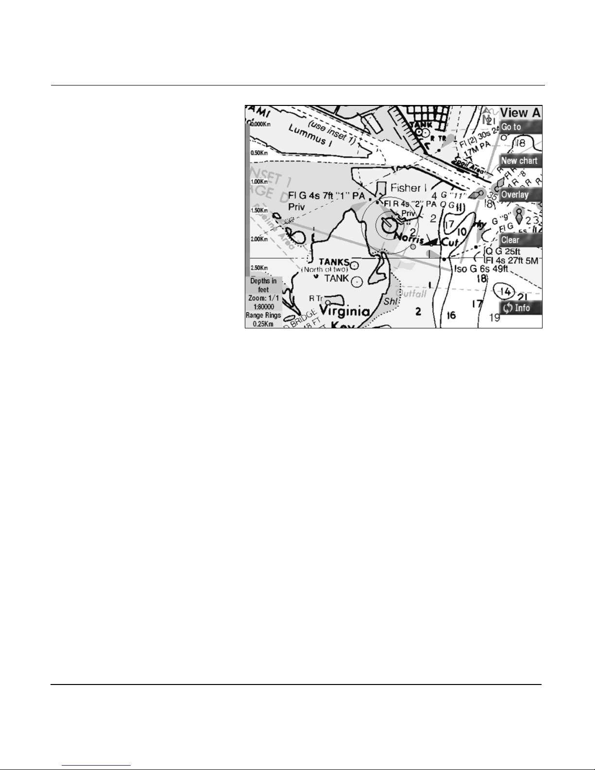
Chart view A
Using chart views A and B
There are two CHART screens, called chart views, designated
by either VIEW A or VIEW B in the upper right-hand corner of
the view. Chart view B offers the same chart-view functions as
chart view A. Using the second view, you can select a different
zoom level, a different location on the chart, different
navigation information, or even a different chart. You can
switch between the two views by pressing the CHART key.
Both CHART views display electronic versions of actual paper
charts. This means that everything that you’re already familiar
with will be displayed right on the CHART screen.
Page 1-18 961/962 Operations and Reference Manual, Rev. A
Page 33

Chapter 1 - Quick Start
Your ves sel
The round vessel symbol in the center of the CHART screen
shows your present position.
Zooming in and out on the chart view
To zoom in and show a more detailed view of the chart, press
the IN key located in the lower right-hand corner of the
control head. To zoom out and show less detail and more area,
press the OUT key located next to the IN key.
Obtaining detailed chart data
For detailed chart data, you should obtain either ChartKit BSB
chart CDs from MapTech or NDI, ChartPack BSB chart CDs
from Maptech, or HCRF chart CDs from the United Kingdom
Hydrographic Office (UKHO). With these choices in
cartography, the 961/962 provides you with truly worldwide
chart coverage. (If your vessel ever moves into an area that
isn’t covered by the charts installed, the 961/962 will
automatically display a plotter grid.) For information on
obtaining BSB or HCRF (ARCS) charts, see “Purchasing charts”
starting on page 13-37.
For further details about using these charts, see “Navigational
chart CDs” starting on page 2-5.
NOTE:
If you’re using BSB charts, make sure you use Maptech Chartkit’s
Second Edition (or higher) BSB-format chart CDs (or anyone else’s
BSB-formatted 2.0 CDs). If you try to install one of the First Edition
CDs, you’ll receive an error message, and will be unable to
complete the installation.
Chart-view features
Each of the six features briefly described below is part of both
chart views:
Vessel predictor line
The green line extending straight out from your vessel’s
symbol is your predictor line, which predicts what your
961/962 Operations and Reference Manual, Rev. A Page 1-19
Page 34
Chapter 1 - Quick Start
position will be at a future time, based on your current COG
and SOG. You can set this time to predict your position in one
minute, two minutes, three minutes, five minutes, or 30
minutes, or turn the line off completely; see “Changing the
chart setup” starting on page 13-24.
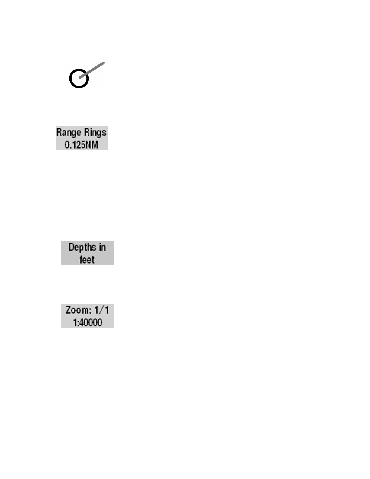
Range rings
Range rings are two sets of fine black circles that surround
your vessel, which is at the center. The radius of the inner ring
is shown in a small box in the lower left-hand corner of the
screen. Because the range rings surround your vessel, they
help you find your position on the CHART screen. For details
about range rings, see “Range rings” starting on page 13-34. To
see an example of range rings on the CHART screen, refer to
the sample display screen on page 1-22. On the DISPLAY
SETUP screen, you can set the distance units to statute miles
(mi), nautical miles (nm), or kilometers (km).
Water depths
The small box in the lower left-hand corner shows how water
depths (spot soundings) are shown on the currently displayed
chart—in feet, meters, or fathoms. These are the numbers from
the paper version of the chart; accordingly, you can’t change
these units of measurements.
Chart scale
The small box in the lower left-hand corner of the CHART
screen shows the chart magnification. As you zoom out, this
number changes to 1/2, 1/4, 1/8, and so on. As you zoom in, it
changes to 2/1, 4/1, etc. The chart scale (such as 1:40000) is
also shown in the box.
• To show a more detailed view of your position on the
chart, press the IN key located in the lower right-hand
corner of the control head: The chart will be magnified.
• For a less detailed view of the chart, press the OUT key:
The displayed chart will cover a larger area.
Page 1-20 961/962 Operations and Reference Manual, Rev. A
Page 35

Chapter 1 - Quick Start
The zoom number in the chart-scale box changes with each
press of the IN or OUT key.
Distance scale bar
On the left-hand side of the CHART screen is a vertical ruler
with alternating red and blue sections. The primary purpose of
the ruler is to provide an approximate scale of distances on the
CHART screen. On the DISPLAY SETUP screen, you can set
the distance units to statute miles (mi), nautical miles (nm), or
kilometers (km).
Differential GPS (DGPS) is a
technique for correcting basic
GPS position data by
receiving additional radio
signals to increase its
accuracy.
Introducing the
chart screen’s menu
keys
DGPS indicator
In the upper left-hand corner of the CHART screen is the word
DGPS, which indicates whether the system is receiving DGPS
corrections to its GPS signals. If corrections aren’t being
received, the DGPS indicator won’t appear on the screen.
The CHART screen is controlled by six menu keys that are
located in a vertical row to the right of the display screen. Each
of these keys controls a function to its left:
• GO TO provides several options to select and navigate to
new position coordinates. For details, see “Navigating to a
point” starting on page 1-24.
• NEW CHART lets you select a different chart for your
vessel’s location from the chart database, or display a
basic plotter grid. For details, see “Selecting new charts”
starting on page 4-8. Each time you briefly press NEW
CHART, the 961/962 cycles automatically through all
appropriate charts. When you press and hold the key,
more chart-selection options are displayed.
961/962 Operations and Reference Manual, Rev. A Page 1-21
• OVERLAY provides the option to superimpose graphic
displays of tide data, currents, and a small echo sounder
picture (if the 490 is installed) onto the CHART screen. For
more information about overlaying graphic displays, see
“Alarms, TideTrack, Currents, and Echo Sounding” starting
on page 12-1.
Page 36

Chapter 1 - Quick Start
• CLEAR—when pressed briefly—clears the CHART screen of
menu keys (press any menu key to restore them); press
and hold CLEAR to clear menu keys and everything else
on the CHART screen, except for your vessel and the
range rings. The clearing action reduces on-screen clutter
so you can see more of the chart.
• INFO (two identical keys) displays at the bottom of the
CHART screen two rectangular INFO BARS, which show
useful information including SOG and COG, numerical
position coordinates, the active waypoint (if any), details
about the chart in use, and so on. Note that the second
INFO key is displayed only after you’ve pressed the one
INFO key at the bottom of the screen. For more about
INFO BARS, see “Showing position coordinates” below,
and see “Displaying information about your position”
starting on page 4-15.
For more about the CHART screen’s menu keys, see
“Chart-view menu keys” starting on page 3-6.
Showing position
coordinates
You can display position coordinates on the CHART screen as:
• lat/lon coordinates from the GPS receiver
• Phantom loran TDs that are calculated from the GPS
coordinates (for when you’d like to see your position
mathematically converted to and displayed in loran TDs)
To set up your CHART screen to display position coordinates
as loran TDs in addition to lat/lon, see “Changing the chart
setup” starting on page 13-24.
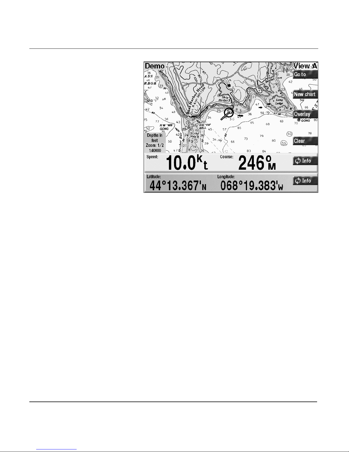
To show your position coordinates and other navigational data
on the CHART screen, press either of the two INFO keys (the
second INFO key will appear only after you press the INFO key
at the bottom of the screen): Several forms of numeric
navigational data appear—in large, easy-to-read numbers—at
the bottom of the screen in an INFO BAR.
Page 1-22 961/962 Operations and Reference Manual, Rev. A
Page 37
Chapter 1 - Quick Start
Chart screen with info bars
Each successive press of either INFO key shows the present
nav data, in the following order:
1. speed-over-ground and course-over-ground (SOG and
COG).
2. lat/lon coordinates (LATITUDE and LONGITUDE).
3. your preferred GRI (GRI) and the best pair of loran
TDs—only available if you’ve chosen to display position
coordinates as loran TDs at the CHART SETUP screen.
4. active waypoint, if any; distance and bearing to the active
waypoint; cross-track error (XTE); estimated time of
arrival (ETA); estimated time enroute (ETE); and
placement of your vessel relative to the desired track.
5. the name and number of the chart in use, its originator
and manufacturer, source date, and chart datum.
6. if you’re displaying a HCRF chart (Hydrographic Chart
Raster Format), the INFO BAR displays the type of chart
series (Navigator or Skipper); expiration date (Navigator
series only); correction level (the Notice to Mariner’s
961/962 Operations and Reference Manual, Rev. A Page 1-23
Page 38
Chapter 1 - Quick Start
7. today’s date and the current local time (from GPS)
8. depth, speed through water, and water temperature (if
To clear an INFO BAR from the CHART screen, press and hold
an INFO key until the INFO BAR disappears. For more about
INFO BARS, see “Displaying information about your position”
starting on page 4-15.
Navigating to a point
Two options exist for navigating to a pair of coordinates from
the CHART screen (if you’re not viewing the CHART screen,
press the CHART key to return to it). You can use the cursor to
designate a position on the chart, or you can enter coordinates
in a dialog box:
number to which the chart has been corrected); name and
date of the Chart CD and Update CD from which the
chart was loaded.
490 is installed)
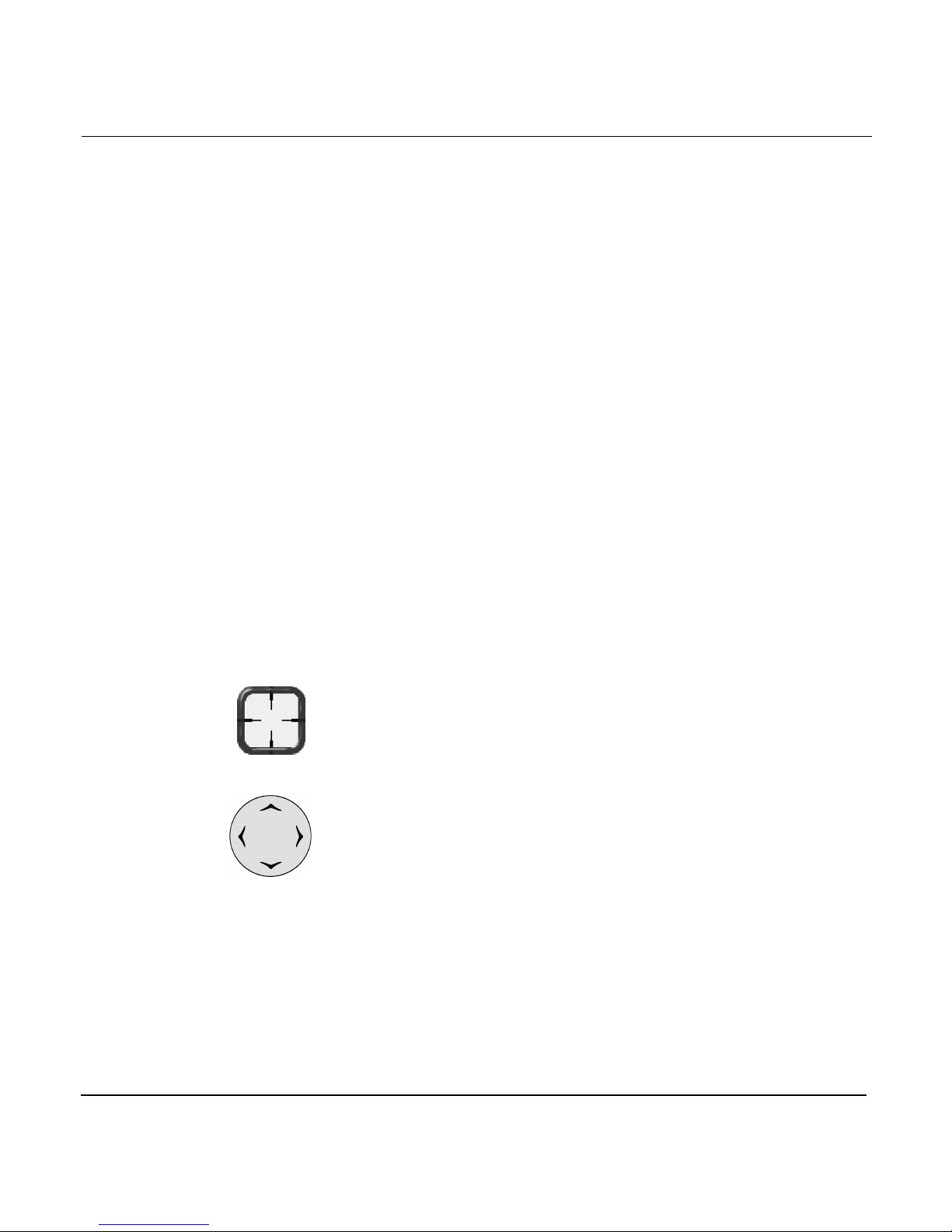
Chart-screen cursor
Cursor pad with
control arrows
To move the cursor small
distances, the best way is to
tap it; this method provides
finer control than does placing
your thumb in the center of the
CURSOR PAD
pushing left, right, up, or
down, although this method
also moves the cursor small
distances.
and gently
Option 1 — Using the cursor to designate a chart position
You can use the cursor to point to a spot on the chart and
navigate there, as follows:
1. To display the cursor (represented by a red square symbol
with crosshairs) and move it to the desired spot on the
chart, press the large CURSOR PAD located in the lower
right-hand corner of the control head.
The CURSOR PAD is multidirectional, so you can move it
diagonally as well as horizontally and vertically. The
longer you hold the CURSOR PAD, the faster the
chart-screen cursor moves.
The distance and bearing to the cursor location, as well as
its lat/lon coordinates, are automatically displayed in the
CURSOR INFO BAR at the bottom of the screen.
Page 1-24 961/962 Operations and Reference Manual, Rev. A
Page 39
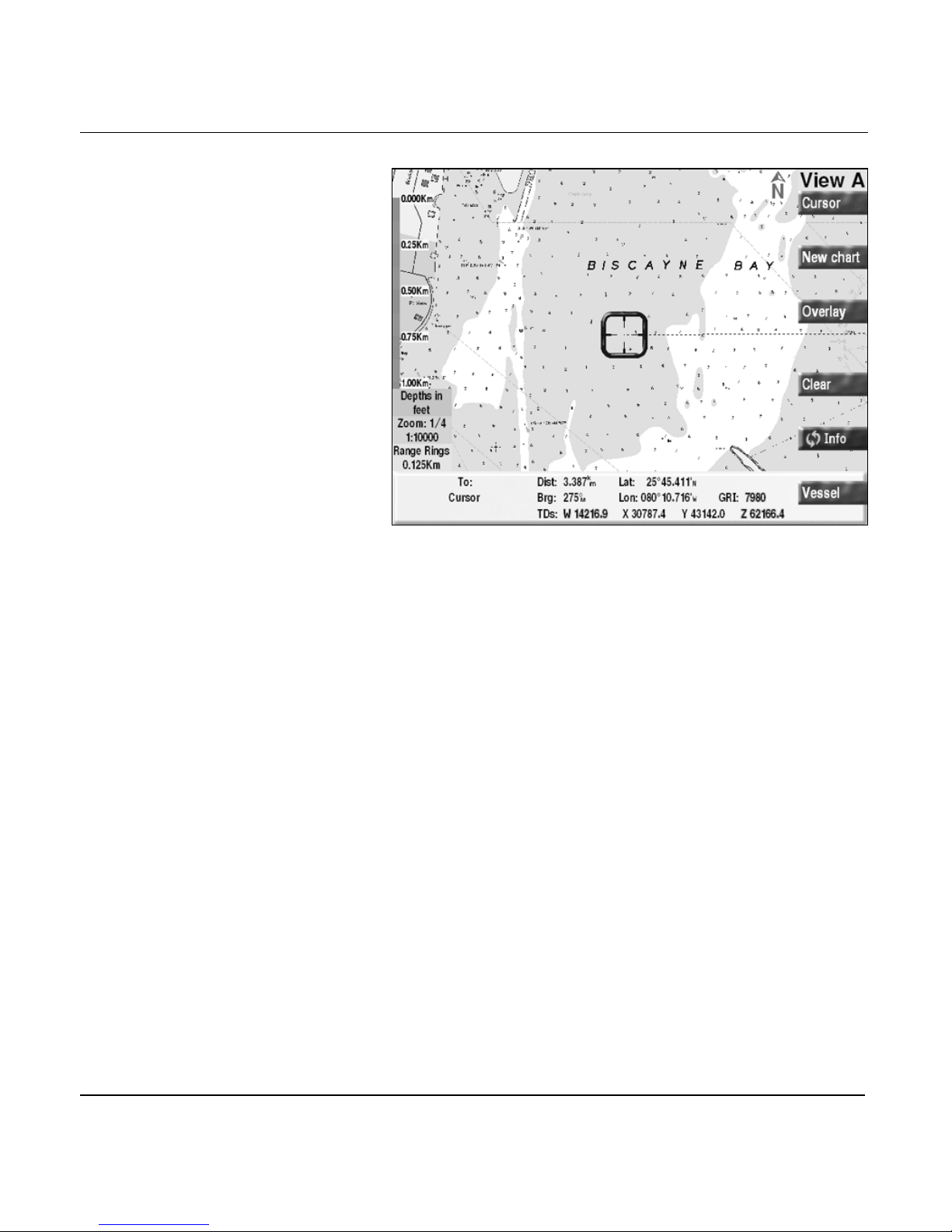
Chapter 1 - Quick Start
Chart screen with cursor location info bar
(To return to showing your vessel in the center of the
chart, press the bottom-right VESSEL key at any time.)
2. Press the CURSOR key.
The SELECTED CURSOR POSITION dialog box
appears, displaying the coordinates of the cursor position.
961/962 Operations and Reference Manual, Rev. A Page 1-25
Page 40
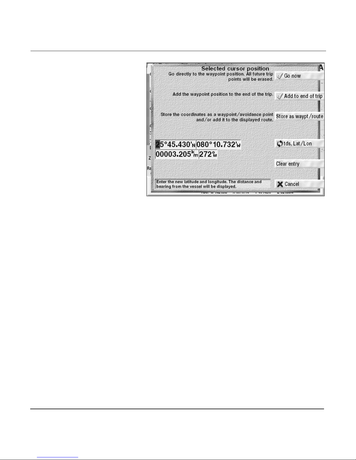
Chapter 1 - Quick Start
Selected cursor position dialog box
3. To navigate directly to the coordinates, press the GO NOW
key (or press the CANCEL key to cancel).
The CHART screen displays a dashed green line—the
“desired track”—from your vessel to the new waypoint,
automatically named COORD. This waypoint is
represented by a green X on the
CHART
screen.
Page 1-26 961/962 Operations and Reference Manual, Rev. A
Page 41
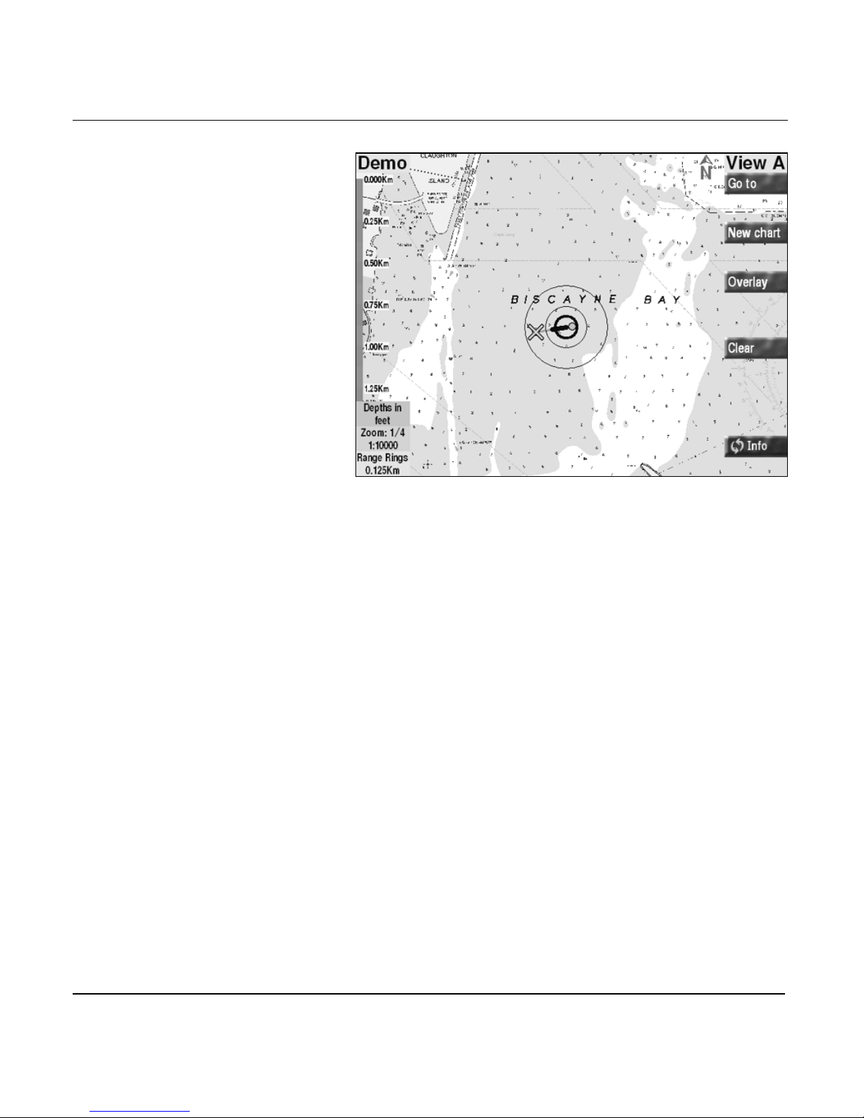
Chapter 1 - Quick Start
Chart screen with COORD waypoint
NOTE:
You can also choose to add those new coordinates to the end of
your trip, or to the end or start of a stored route. For details about
these options, see “Using the cursor on the chart screen” starting on
page 4-17.
Option 2 — Entering coordinates
Your second option for navigating to a point is to enter
numeric coordinates as lat/lon, Loran-C TDs, or distance and
bearing, as follows:
1. From the CHART screen, press the GO TO key.
The
GO TO COORDINATES
coordinates of your active waypoint, if any, or else the
coordinates of your most recent position, are displayed.
dialog box appears. The
961/962 Operations and Reference Manual, Rev. A Page 1-27
Page 42
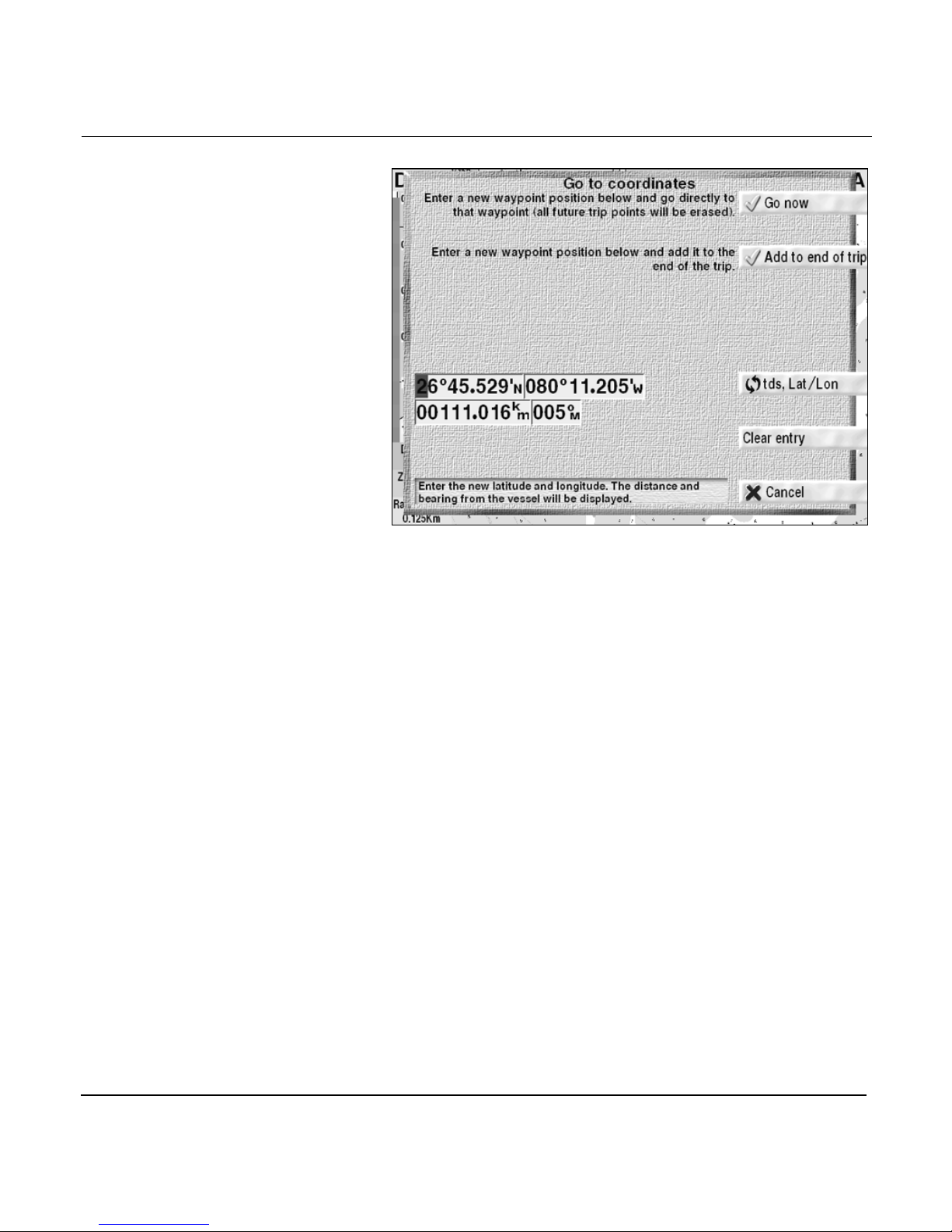
Chapter 1 - Quick Start
Go to coordinates dialog box
2. To change these coordinates, use the KEYPAD to enter
new coordinates: Press the CURSOR PAD right to move
the flashing cursor to the longitude field or press down to
move to the distance and bearing fields, then use the
KEYPAD to enter new coordinates. (For details about
using the KEYPAD to enter data, see “Entering data”
starting on page 2-7.) To display the coordinates as lat/lon
or TDs, press the LL/TDS key.
Page 1-28 961/962 Operations and Reference Manual, Rev. A
Page 43
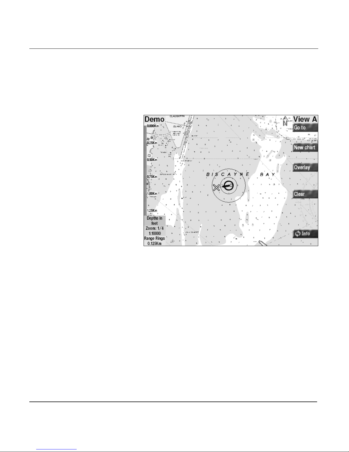
Chapter 1 - Quick Start
3. To navigate directly to the new coordinates, press the GO
NOW key (or press the CANCEL key to cancel).
The
CHART
screen displays a green line—the “desired
track”—to the new waypoint, automatically named
COORD
the
. This waypoint is represented by a green X on
CHART
screen.
Chart screen with COORD waypoint
961/962 Operations and Reference Manual, Rev. A Page 1-29
Page 44

Chapter 1 - Quick Start
Reading and clearing alarm messages
To show the ALARMS screen, and read and clear an alarm
message:
1. Press the STAR key until you reach the ALARMS screen.
The alarm message with its corresponding time and date
is shown in the NEW ALARMS box. The word NEW
means that you haven’t acknowledged the alarm
message or the message hasn’t self-cleared.
2. To acknowledge an alarm message, press the CLEAR
ALARM key at the upper right side of the screen.
3. To return to the CHART screen, press the CHART key.
Some alarms can’t be manually cleared; for complete details
about alarms, see “Alarms, TideTrack, Currents, and Echo
Sounding” starting on page 12-1.
NOTE:
During an alarm condition, the alarm message always appears on
whatever screen you’re displaying (including the
SOUNDER
ALARMS
message at the
screen, if the 490 is installed) as well as on the
screen itself; however, you can only clear an alarm
ALARMS
screen.
ECHO
Page 1-30 961/962 Operations and Reference Manual, Rev. A
Page 45

2
Introducing the 961/962
System overview . . . . . . . . . . . . . . . . . . . . . . . . . . 2-2
Introducing the controls . . . . . . . . . . . . . . . . . . . 2-6
Entering data . . . . . . . . . . . . . . . . . . . . . . . . . . . . . . 2-7
Caring for the system . . . . . . . . . . . . . . . . . . . . . . 2-8
About interfacing the system . . . . . . . . . . . . . 2-10
Introducing GPS and DGPS . . . . . . . . . . . . . . . 2-11
T
his chapter introduces the 961/962’s major features and
controls, discusses basic maintenance, and provides an
introduction to GPS and DGPS. Read this chapter to learn the
broader concepts of 961/962 operations and marine
navigation.
961/962 Operations and Reference Manual, Rev. A Page 2-1
Page 46

Chapter 2 - Introducing the 961/962
System overview
This section summarizes ten of the major features: GPS; DGPS;
navigation; waypoints and routes; echo sounder; avoidance
points; the CHART screen; navigational chart CDs (the 961/
962 is compatible with HCRF charts—the format for ARCS
charts—as well as BSB-format charts); the TideTrack function;
and the display of currents.
GPS features
DGPS features
(961XD/962XD
only)
The following GPS features are offered:
• 12-channel GPS precision and dependability
• accurate position data—worldwide
• one-second update of position, speed, and heading
• data available in any weather—24 hours a day
For the best in GPS accuracy, the Northstar 961XD/962XD
features an internal, two-channel DGPS receiver that accepts
DGPS signal corrections from shore-based transmitters called
beacons. These transmitting beacons emit radio signals, which
may be affected by lightning.
The 961XD/962XD uses these DGPS signal corrections to
display your position (a position fix), as accurately as one to
three meters.
The 961XD/962XD’s DGPS feature offers:
• a fully automatic DGPS beacon receiver
• accuracy of one to three meters (one meter equals slightly
more than one yard)
For details about DGPS, see “Differential GPS corrections”
starting on page 2-13.
Navigation features
Page 2-2 961/962 Operations and Reference Manual, Rev. A
There are two separate, high-resolution, color chart views that
show:
• continuous DGPS usage indicator on the CHART screen
• one-second update of DGPS information
• your vessel’s present position
Page 47

Chapter 2 - Introducing the 961/962
• nearby waypoints
• lat/lon in large, easy-to-read numbers
• loran TDs (and Group Repetition Interval, or GRI)
• speed-over-ground (SOG) and course-over-ground (COG)
• distance and bearing to the active waypoint, if any
• today’s date and the current local time
• cross-track error (XTE)
• estimated time enroute (ETE)
• estimated time of arrival (ETA)
• today’s trip (past, active, and future waypoints)
• tide data for the 24-hour period of any chosen date
• currents for the 24-hour period of any chosen date
Waypoint,
avoidance point,
and route features
The waypoint, avoidance point, and route features include:
• storing up to 2,000 waypoints and 1,000 routes
• storing up to 200 avoidance points (and displaying them
on the CHART screen and the 3-D STEER screen)
• storing and displaying waypoints in several ways:
>
one of 23 different symbols can be assigned to each
waypoint for display on the CHART screen
>
the WAYPOINTS screen can be sorted by symbol, name,
distance, or bearing
>
on a separate TRIP screen
• instantly locating any waypoint on the WAYPOINTS
screen using “Quick Search”
• editing routes and waypoints directly from the CHART
screen, WAYPOINTS screen, and ROUTES screen
961/962 Operations and Reference Manual, Rev. A Page 2-3
Page 48
Chapter 2 - Introducing the 961/962
Echo sounder
Chart-screen
features
If enabled, the ECHO SOUNDER screen indicates the depth of
the water under the vessel, the position and depth of fish, and
the contours of the seabed. This information comes from
Northstar 490 Echo Sounder, which is connected to the 961/
962 and a Northstar-recommended transducer. For details
about using the echo sounder, see the Northstar 490 Echo
Sounder Operations Manual (part number GM490).
The CHART screens maximize usability by including such
features as fast chart redraw, an LCD screen with easy-to-read
numbers, and a plotter function for up-close navigation.
Chart redraw
Normally, as you navigate, your vessel remains centered on
the CHART screen, and the chart moves underneath it. The
high-speed screen redraw feature automatically keeps the
chart visible—even as you move from one chart to the next.
Lighting
The liquid crystal display (LCD) screen is easy to see in all
kinds of light—from full, direct sunlight to total darkness.
Anti-reflection treatment of the screen removes over 90
percent of the reflection and glare usually found in bright
sunlight. Moreover, the screen is fully lit for nighttime use.
To adjust the screen’s brightness, press the BRIGHTNESS key
(this key isn’t labelled) to the left of the display screen. For
details, see “Brightness key” starting on page 3-27.
Plotter function
The plotter function helps you navigate if you’re ever in areas
that aren’t represented on your installed navigational charts.
The plotter function is particularly useful when you’re fishing
out in the open ocean and using stored tracks and waypoints
as reference points. The your boat symbol is automatically
displayed on a north-up grid of lat/lon lines while the system
plots your position and waypoints. When you’re using the
plotter function, the menu keys to the right of the chart views
Page 2-4 961/962 Operations and Reference Manual, Rev. A
Page 49

Chapter 2 - Introducing the 961/962
still let you perform the same functions as when viewing a
chart.
For more about the CHART screen, see “Understanding
electronic charts” starting on page 4-2.
Navigational chart
CDs
You can tremendously enhance the usefulness of your system
by using chart CDs for the regions where you plan to travel.
Furthermore, new electronic charts are very likely to be more
current than your paper charts. Northstar recommends that
you acquire electronic charts, although it is possible to use the
961/962 and navigate without them.
The 961/962 is compatible with either of the following types of
charts (or both):
• BSB 2.0 or newer format navigational charts (ChartKit
CDs) supplied by either Maptech or NDI. These are
high-quality, high-resolution NOAA digital charts
providing chart coverage for most of the world. Each CD
contains about 75 to 200 different charts covering a
specific area of coastline.
• ChartPak CDs also supplied by Maptech. These charts are
similar to those supplied on ChartKit CDs as above.
• Hydrographic Chart Raster Format (HCRF) navigational
charts, such as ARCS chart CDs supplied by the United
Kingdom Hydrographic Office (UKHO). ARCS charts
(Admiralty Raster Chart Format) are raster images, digital
reproductions of official British Admiralty paper charts
that provide superior chart-image quality and global chart
coverage on a total of 3000 charts.
All the data on these CDs comes from scanning land-mass
shapes, nav-aid names and locations, depth contours, and
other information directly from the official paper charts into
an electronic format used by the 961/962. Between the three
types of chart formats, you have chart access to every major
port, all popular boating areas, and major shipping routes.
Each CD covers a specific geographic area, providing CHART
screen zoom in/out levels from maximum detail to a
less-detailed overview.
961/962 Operations and Reference Manual, Rev. A Page 2-5
Page 50

Chapter 2 - Introducing the 961/962
For information on purchasing BSB, ChartPak, or HCRF (ARCS)
charts, see “Purchasing charts” starting on page 13-37.
The CD-ROM drive is used to install all charts onto the
internal chart database. For information about how to load
charts, see “Loading, updating, and deleting charts” starting on
page 13-35.
TideTrack
Currents
The TideTrack feature displays a 24-hour tide graph for any of
over 3,000 National Oceanic and Atmospheric Administration
(NOAA) and National Ocean Service (NOS) tide stations
covering the entire U.S. coastline, including Alaska and Hawaii
as well as much of the western Canadian coastline. You can
view tides for today or any other date you choose.
For more about viewing tides, see “Viewing tide-station data”
starting on page 4-10; for full details about TideTrack, see
“Understanding the TideTrack function” starting on page
12-11.
The currents feature displays a 24-hour current speed/
direction graph for any date to choose. For more about
viewing currents, see see “Understanding the currents
function” starting on page 12-15.
Introducing the controls
Collectively, the controls refer to the soft rubber buttons, or
keys, on the front face of the control head. Feel free to
experiment with these controls! You can’t hurt anything; in
fact, you can probably learn many new ways of operating the
system more efficiently.
Whether you’re entering, changing, or deleting information,
you’ll be asked to confirm your actions before they affect an
operation. And you can always cancel a function at the last
second. On each screen, menu keys with a
the final step in a sequence, the step that will actually carry
out the operation. Menu keys with a red
operation, and return you to the screen you were previously
viewing.
Page 2-6 961/962 Operations and Reference Manual, Rev. A
✔✔✔✔
mark designate
mark cancel an
✖
Page 51
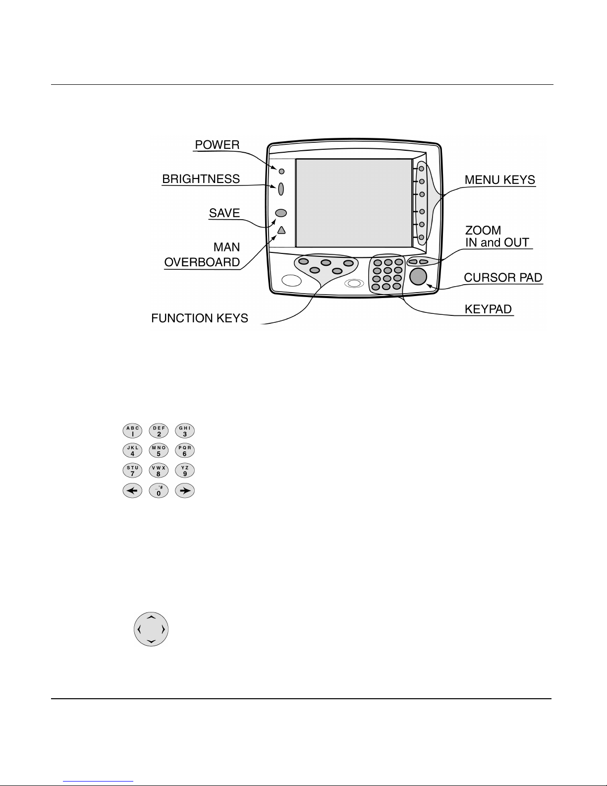
Chapter 2 - Introducing the 961/962
For a detailed description of the controls, see “Using the
Controls” starting on page 3-1.
Figure 2: 961/962 controls
Entering data
Keypad
Cursor pad
The 12-button alphanumeric KEYPAD is used for entering
numbers, letters, or special characters into a variety of fields,
such as waypoint coordinates, waypoint names, and so on.
A typical entry screen will display several items of data. First,
choose the item you want to change by pressing the CURSOR
PAD to move the flashing cursor to that item. The cursor
appears as a flashing red box that represents the place where
the next typed character is to appear. The flashing cursor
indicates which character position will be written into. Use the
LEFT ARROW and RIGHT ARROW keys on the KEYPAD to
move the flashing cursor to the next character you want to
enter. In some fields, numbers will automatically go into their
correct places. At times, a CLEAR ENTRY key or a RESTORE
ENTRY key may be available; these keys clear the field of data,
or restore the cleared field, respectively.
Press the up and down arrows of the CURSOR PAD to move to
the next line you want to enter.
961/962 Operations and Reference Manual, Rev. A Page 2-7
Page 52
Chapter 2 - Introducing the 961/962
When the item(s) is correct, press the DONE or ACCEPT key.
The full screen of data is accepted and stored in the database.
In some fields, such as waypoint distance, bearing, and lat/lon,
you can enter only numbers. In other fields, such as waypoint
names, you can enter letters, numbers, and punctuation
characters.
Entering letters
and numbers
Each key is labeled with three letters or other special
characters, and a number. Here’s an example: The upper
left-hand key is labeled with the letters A, B, C, and the
number 1. To enter these characters, press the key once to
show the letter A; press the key again to show the letter B;
press a third and fourth time to show the letter C and the
number 1, respectively. A fifth keypress returns you to the
letter A. The other nine keys use this same method for data
entry.
To enter data:
1. Find the key containing the desired letter, number, or
character.
2. To display the letter, number, or character, press that key
one to four times.
3. To move the cursor to the next position, press the RIGHT
ARROW key. When entering numbers, each new keypress
automatically moves the field’s blinking cursor to the
next position.
4. Repeat for each letter, number, or character.
Caring for the system
You must maintain the 961/962 at a certain level to retain
peak performance. Topics covered here include basic
maintenance, weatherproofing, cleaning the screen, and
safeguarding the chart CDs. For further information about
maintenance, including how to return a 961/962 for service,
see “Maintenance functions” starting on page 14-17.
Page 2-8 961/962 Operations and Reference Manual, Rev. A
Page 53
Chapter 2 - Introducing the 961/962
Basic maintenance
Weatherproofing
your 961/962
The following information will help you maintain your 961/
962’s high performance level:
• keep fingerprints off the display screen (remove any prints
with a lens cleaning cloth)
• don’t scratch the display by scraping a sandy or salty cloth
across it
• remove dirt and grime with Windex and a soft cloth, or
else soap and water
• don’t try to open the control head’s case—there aren’t any
user-serviceable parts inside
• use the protective plastic cover during periods of
inactivity
• never expose the processor to moisture of any kind—it is
not water-resistant! (the control head is waterproof)
CAUTION!
Excessive heat can cause short- and long-term
damage to the 961/962. Although it can recover
from short-term effects, long-term damage may be
permanent. When the 961/962 isn’t in use and is
exposed to the hot sun, always shield it with the
protective plastic cover.
Saltwater spray
If left disconnected, the rear connectors behind the control
head may corrode slightly from exposure to saltwater spray.
Keep the plastic caps of the rear connectors in place at all
times. Protect the entire 961/962 from prolonged exposure to
the elements by mounting it, if possible, in a relatively dry
area. At the end of a trip, wipe the control head dry.
Cleaning the screen
961/962 Operations and Reference Manual, Rev. A Page 2-9
Be careful when cleaning the glass window covering the
display screen. Although it’s scratch-resistant, you may
damage the anti-reflective coating if you use a dry cloth to
wipe dirt off. When wiping the window, always use a damp cloth
Page 54

Chapter 2 - Introducing the 961/962
or a dry, clean, microfiber-type lens cleaning cloth. To dissolve
any oil or grease on the screen, use a small amount of window
cleaner or alcohol. Pre-packaged moist towelettes, especially
those containing a small amount of alcohol, are excellent for
cleaning the display screen. You may want to keep a supply
handy for removing fingerprints and other smudges.
Whenever possible, avoid touching the glass with your fingers,
since the natural oils of your hand will temporarily affect the
characteristics of the screen, causing your fingerprints to
appear as bright reflections. These will disappear, however,
when the screen is cleaned as described above.
Safeguarding the
chart CDs
To prevent moisture and dirt from entering the processor,
keep the CD-ROM drive’s door and tray closed unless you’re
inserting or removing a CD. Because the 961/962 copies and
stores CD data onto its internal hard drive, you’ll only have to
insert these CDs during their installation. You shouldn’t have
to open or close the drive for any other reason.
Keep all of your CDs in a safe, watertight place where they
won’t be damaged or exposed to sunlight and any other kind
of heat.
About interfacing the system
You can interface the 961/962 to a variety of devices,
including autopilots, paper plotters (traditional navigation
devices using paper charts), radar plotters (navigation devices
tracking radar data as well as waypoints), instrument displays,
and personal computers, and to the Northstar 490 for echo
sounding.
The 961/962 features the following interface ports:
Page 2-10 961/962 Operations and Reference Manual, Rev. A
• three independent output ports for driving
NMEA-compatible devices
• three input ports for accepting data from other NMEA
devices
• an auxiliary (aux) port for either input or output of
SC-104 DGPS corrections and for uploading/downloading
waypoints, routes, or tracks to/from a personal computer
Page 55

For details on interfacing the Northstar 490 to the 961/962,
refer to the Northstar 490 Echo Sounder Installation Manual
(GM491).
For details on interfacing the 961/962 with other devices, see
the Northstar 961/962 GPS Chart Navigator Installation
Manual (GM1901).
Introducing GPS and DGPS
This section introduces the GPS and DGPS navigation systems,
and describes how these systems relate to the Northstar 961/
962. If you’re new to navigation, you may begin without
understanding anything about these navigational concepts.
However, Northstar recommends that you read this section at
some point to become familiar with the concept of GPS and
DGPS.
Chapter 2 - Introducing the 961/962
What is GPS?
The United States’ Global Positioning System (GPS) is now fully
operational. Developed by the U. S. Department of Defense
(DOD), the GPS system comprises 21 active satellites with
three additional spares. Using these satellites, GPS encircles
the earth with navigation data.
961/962 Operations and Reference Manual, Rev. A Page 2-11
Page 56
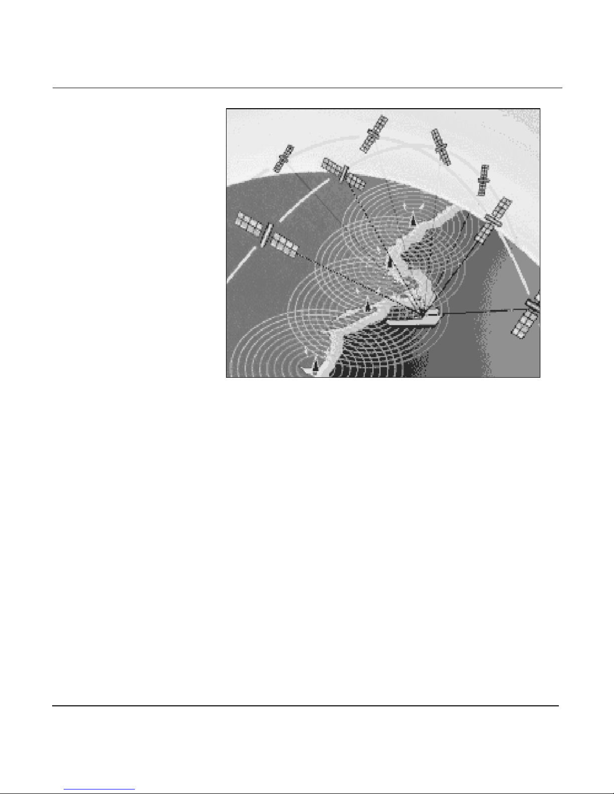
Chapter 2 - Introducing the 961/962
Absolute and
repeatable accuracy
Selective availability
Figure 3: GPS satellites communicating with vessel
GPS’s major advantage over all other commercially-available
navigation systems, including loran, is its all-weather,
worldwide availability, and its absolute accuracy. (Those
readers interested in loran should see “Understanding
Loran-C” starting on page 5-7.) Absolute accuracy refers to the
ability of a navigation device to determine your actual lat/lon
coordinates on the surface of the earth, as compared to
position data determined from a paper chart or other
reference. Repeatable accuracy, on the other hand, refers to the
ability of a particular navigation device to return to a position
whose lat/lon coordinates were previously recorded by this
same navigation device.
The Department of Defense developed a system of built-in
errors, called Selective Availability (SA), which was introduced
as a national defense strategy to intentionally degrade the GPS
solution. (The Department of Defense wanted to avoid the
possibility that its precision could be used by hostile forces as
Page 2-12 961/962 Operations and Reference Manual, Rev. A
Page 57

Chapter 2 - Introducing the 961/962
a source of accurate targeting data against U.S. interests.)
When it was enabled, SA reduced GPS’s absolute and
repeatable accuracy from a maximum of 30 meters (better
than 100 feet) 95 percent of the time, to 100 meters (better
than 330 feet) 95 percent of the time. However, this accuracy
didn’t meet the Coast Guard’s requirement of 8-20 meters for
navigating in harbors, so the Coast Guard developed a system
of differential corrections, or differential GPS (DGPS) to allow
them to effectively circumvent SA’s built-in errors. SA was
officially ended early in the year 2000, but the advantage of
using DGPS over non-SA GPS is still clear and desirable for the
safety of marine navigation: Mariners who need better than
100 meters probably will also need better than 30 meters.
Differential GPS
corrections
The majority of mariners use GPS in conjunction with a chart
plotter, and for any given position solution there is an error
budget. Dilution of GPS precision, errors in cartography from
both government and private sources, datum shifts, latency of
displayed position fix and so on, all compound the error in the
resulting displayed position fix. For example, imagine a chart
plotter at full-scale zoom showing a channel 200 feet wide (60
meters). A vessel navigating through that channel may well
appear to be “on the rocks” if it is 30 meters out of place!
Although this magnitude of error won’t always be the case, the
prudent navigator should choose the maximum margin of
safety. Furthermore, the precise location of bottom features for
fishing and diving is significantly degraded without DGPS, and
therefore would usually be of little use unless there’s better
than the 100 feet of accuracy (30 meters) of non-differential
GPS.
These differential corrections are generated by fixed reference
stations, and then broadcast by marine radiobeacons over a
relatively limited area—usually a maximum broadcast radius of
250 miles in any direction—to differential-capable GPS (DGPS)
receivers. (The exact geographic positions of these fixed
reference stations are used to calculate the position
corrections, which are based on GPS data received from the
earth-orbiting GPS satellites.) These corrections are broadcast
to the DGPS receivers, which convert this data into extremely
precise position, heading, and speed data. Referred to as
961/962 Operations and Reference Manual, Rev. A Page 2-13
Page 58

Chapter 2 - Introducing the 961/962
beacons, the transmitters are situated at various locations
along the U.S. coastline, Great Lakes, and major rivers.
What does all this mean? Using DGPS, the 962’s
high-performance 12-channel GPS receiver and optional
two-channel internal differential receiver work together to
provide position accuracy of one to three meters 50 percent of
the time, and under four meters 95 percent of the time.
(Remember: one meter equals just over one yard!)
Differential corrections are invaluable when navigating in
such narrow or congested areas as ports and waterways, or
wherever you require extreme accuracy to locate a precise
area (retrieving lobster traps, returning to a favorite diving
spot, and so on.)
The 961/962 displays lat/lon coordinates to thousandths of
minutes (approximately six feet). When using a radar plotter or
paper plotter, DGPS corrections dramatically improve the
steadiness of your displayed plot line.
Monitoring GPS signal integrity
Besides providing highly accurate position data, DGPS
monitors the integrity of the received GPS signals. Integrity
monitoring helps detect a satellite problem in seconds,
compared to hours using non-differentiated GPS. How? The
integrity monitor tells the DGPS receiver to automatically stop
using any unhealthy satellites.
Page 2-14 961/962 Operations and Reference Manual, Rev. A
Page 59

3
More navigation terminology . . . . . . . . . . . . . 3-2
PWR key . . . . . . . . . . . . . . . . . . . . . . . . . . . . . . . . . . 3-3
Function keys . . . . . . . . . . . . . . . . . . . . . . . . . . . . . 3-5
Brightness key . . . . . . . . . . . . . . . . . . . . . . . . . . . 3-27
SAVE key . . . . . . . . . . . . . . . . . . . . . . . . . . . . . . . . . 3-28
MOB key . . . . . . . . . . . . . . . . . . . . . . . . . . . . . . . . . 3-28
IN and OUT keys . . . . . . . . . . . . . . . . . . . . . . . . . 3-31
Cursor pad . . . . . . . . . . . . . . . . . . . . . . . . . . . . . . . 3-31
Arrow keys . . . . . . . . . . . . . . . . . . . . . . . . . . . . . . . 3-32
Menu keys . . . . . . . . . . . . . . . . . . . . . . . . . . . . . . . 3-33
Using the Controls
T
his chapter describes all of the Northstar 961/962's controls
in detail, except for the alphanumeric KEYPAD—for this
information, see “Entering data” starting on page 2-7.
961/962 Operations and Reference Manual, Rev. A Page 3-1
Page 60
Chapter 3 - Using the Controls
More navigation terminology
Some users who are new to navigation may find unfamiliar
terms in this chapter; these terms have a special meaning
throughout the manual. Highlight Two defines several
navigation expressions with which experienced navigators
may already be familiar.
Highlight Two: More navigation terms
ARCS: Admiralty Raster Chart Service. The
electronic chart service designed by the United
Kingdom Hydrographic Office (UKHO).
Course line: A line of travel from your present
position to your upcoming (active) waypoint.
Differential GPS (DGPS): A U.S. Coast Guard
(USCG)-developed system of GPS corrections that
further increases position accuracy (requires a
DGPS receiver). For more information, see
“Introducing GPS and DGPS” starting on page
2-11.
Hydrographic Chart Raster Format (HCRF): A
chart format designed by the United Kingdom
Hydrographic Office, and used by ARCS (see
ARCS definition above).
Leg: The line, or path, between any two waypoints
in a route or a trip.
Nav aid: Aids to navigation often used on
coastal and inland waters. Nav aids primarily
comprise buoys, lighthouses, and daymarkers,
and their purpose is to warn you of such hidden
dangers as underwater hazards, and to help
you safely navigate through specific waterways
and channels.
Trip: A sequence of waypoints comprising
today’s journey—a record of waypoints
(including past, active, and future ones),
coordinates, and routes. The trip function
provides a way to check your actual progress,
as well as make changes, while you travel. On
the
CHART
your trip according to its legs: the past leg of
the trip is displayed in yellow; the course line to
the active waypoint is displayed in green; and
future trip legs are displayed in light blue.
screen, the 961/962 color-codes
Page 3-2 961/962 Operations and Reference Manual, Rev. A
Page 61
PWR key
Chapter 3 - Using the Controls
Turning the system
on and off
Pressing the PWR key turns the 961/962 (the control head or
heads and the processor) on and off.
Turning the system on
To turn the 961/962 on:
1. Press the PWR key.
After several minutes, the
appears, which is displayed for about five to ten seconds.
INITIAL STARTUP
screen
961/962 Operations and Reference Manual, Rev. A Page 3-3
Initial startup screen
After the
screen is displayed for about 10 seconds. After the
SYSTEM TEST
is displayed for about 10 seconds. To create a personal
owner’s message, such as the name of the vessel and its
owner, see “System security” starting on page 13-7. After
the OWNER’S MESSAGE screen is displayed, the
ADVISORY MESSAGE screen is displayed, warning you
not to rely solely on chart cartography for safe navigation.
INITIAL STARTUP
screen, the
screen, the
OWNER’S MESSAGE
SYSTEM TEST
screen
Page 62

Chapter 3 - Using the Controls
2. To proceed, accept the ADVISORY MESSAGE by pressing
any of the five function keys.
If chart CDs for your geographical area have been
installed onto the 961/962’s hard drive, and after GPS
signals are acquired, you’ll see your vessel symbol
centered on the
CHART
screen at your present position.
Until GPS signals are acquired, a small position-fix circle
will be located at the last known position.
If there aren’t any charts covering your geographic
location installed on the hard drive, a plotter grid is
displayed instead of a chart.
NOTE:
Two minutes after power-up and thereafter, if GPS data is
unavailable for more than three seconds, GPS position is
considered unknown, and a non-clearable GPS alarm is activated.
You’ll receive the alarm message
or NO GPS FIX
course-over-ground (COG), lat/lon, and TDs and GRI are replaced
by dashed lines.
. The displays of speed-over-ground (SOG) and
GPS ACQUIRING
(at power-up)
Turning the system off
The procedure for turning off a 961/962 with two control
heads is slightly different than for turning off a system with
one head.
Single-head system
To turn off the entire system (the control head and the
processor):
1. Press and hold the PWR key for approximately three
seconds, and the system will turn off.
Two-head system
To turn off a 961/962 with two control heads that are on:
1. Press and hold the PWR key for approximately three
seconds, and the POWER-OFF dialog box appears.
Page 3-4 961/962 Operations and Reference Manual, Rev. A
Page 63
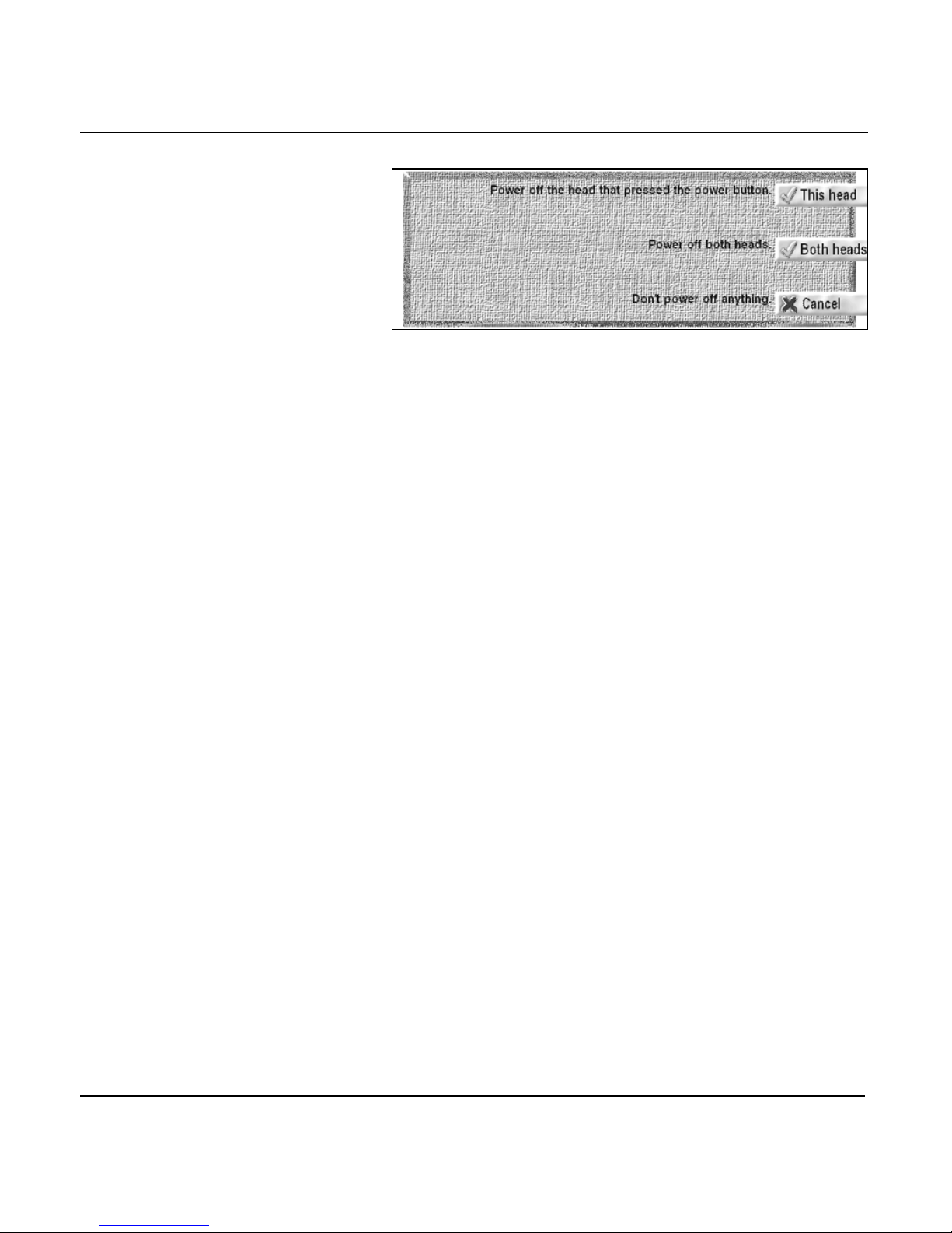
Chapter 3 - Using the Controls
Power-off dialog box
2. To turn off only the head where you pressed the PWR key,
press the THIS HEAD key. Otherwise, to turn off the entire
system including the processor, press the BOTH HEADS
key.
Using the
test-power switch
Function keys
The processor has a TEST-POWER switch located on the
upper-left corner of the rear of the processor case (when
viewed from the back). When this switch is set to AUTO, the
control head’s PWR button automatically turns off the
processor. When set to TEST, the processor stays on—even if
you turn the control head off. This setting lets you save power
by turning off the control head while the processor is running,
and lets you separately test the functioning of the head and
processor, if necessary. Unless the 961/962 is being tested,
make sure the TEST-POWER switch is set to AUTO.
The five function keys located across on the lower left part of
the control head—CHART, STEER, WAYPTS/ROUTES, STAR,
and TRIP—control the functions you’ll use most often.
NOTE:
Pressing a function key immediately cancels any edit-in-progress
(such as waypoint entry) so that you can view the data requested by
your function keypress. To resume editing at the previous screen,
you must return to that screen and re-enter the data that you lost
when you pressed the function key. To purposely cancel an
edit-in-progress, however, you’d normally press the
CANCEL
key.
961/962 Operations and Reference Manual, Rev. A Page 3-5
Page 64
Chapter 3 - Using the Controls
CHART key
Use the CHART key to display a chart-view screen showing
your position. Your position is shown graphically and
numerically: The graphic view shows your position directly on
the CHART screen. Numerically, you can display your position
as lat/lon coordinates (or TDs) on either of two separate INFO
BARs (see next page) that you access on the chart-view screen.
Chart views A and B
The CHART key switches between two independent CHART
screens, called chart views A and B. You can preset each view
to a useful zoom level, a particular chart, or an INFO BAR
display, and you can instantly select one view or the other.
Using this feature, you can view one screen with your present
position, and a second screen with your destination
position—all with just a single keypress!
Chart-view menu keys
The menu keys are the six round keys to the right of the
display screen. These keys perform different functions at
different times, depending on what screen you’re displaying.
The CHART screen has six menu keys—GO TO, NEW CHART,
OVERLAY, CLEAR, and two INFO KEYS (the second INFO
KEY appears only after you’ve pressed the first); collectively,
these keys control a range of navigation functions.
Page 3-6 961/962 Operations and Reference Manual, Rev. A
Page 65
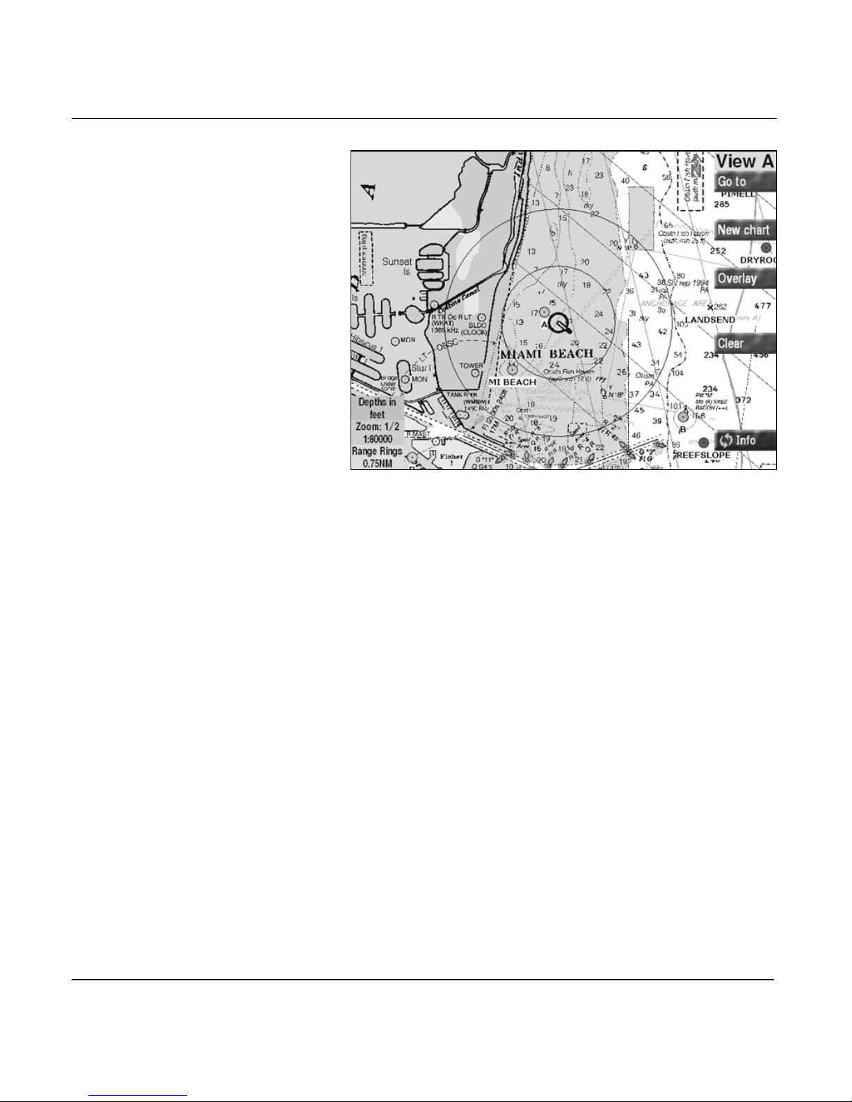
Chapter 3 - Using the Controls
Chart screen with menu keys
Use the GO TO key to:
• go to new coordinates now
• add new coordinates to the end of your trip
• restart your track to the active waypoint, if necessary
Use the NEW CHART key to:
• view charts of your present position in increasingly better
scales (press briefly)
• view a list of all charts that cover the vessel’s location
(press and hold the NEW CHART key) or the cursor’s
location (first press the CURSOR PAD, then press the
NEW CHART key)
• view a list of all charts in the chart database (press and
hold)
• change the usage of any chart (press and hold)
• select a lat/lon grid instead of a chart (press and hold)
• retrieve information about any selected chart (press and
hold)
961/962 Operations and Reference Manual, Rev. A Page 3-7
Page 66

Chapter 3 - Using the Controls
Use the OVERLAY key to:
• view the NOAA tide station overlay on the CHART screen
and view 24 hours of graphical tide data for a chosen date
• view the currents overlay on the CHART screen and view
24 hours of currents data for a chosen date
• view the echo sounder overlay on the CHART screen
Use the CLEAR key to:
•clear the CHART screen of menu keys (by pressing briefly)
• clear the CHART screen of menu keys, INFO BARs, and
other chart symbols (by pressing and holding the CLEAR
key for a few seconds)
Use the INFO keys to:
• display speed-over-ground (SOG) and course-over-ground
(COG)
• display lat/lon coordinates
• display Loran-C GRI and TDs (if specified at the CHART
SETUP screen)
• display your active waypoint (if any), distance and bearing
to the waypoint, numerical and graphical cross-track error
(XTE), estimated time of arrival (ETA), and estimated time
enroute (ETE)
• display details about the chart-in-use, including its name,
number, source, and revision date. If you’re displaying an
HCRF chart such as ARCS, the INFO BAR displays the
chart series (Navigator or Skipper); expiration date
(Navigator series only); correction level (the Notice to
Mariner’s number to which the chart has been corrected);
name and date of the corresponding Chart CD; and name
and date of the corresponding Update CD.
• display today’s date and the current local time
• depth, speed through water, and water temperature (if
490 is installed)
For in-depth information about using the charts, see
“Understanding the Chart Screen” starting on page 4-1.
Page 3-8 961/962 Operations and Reference Manual, Rev. A
Page 67
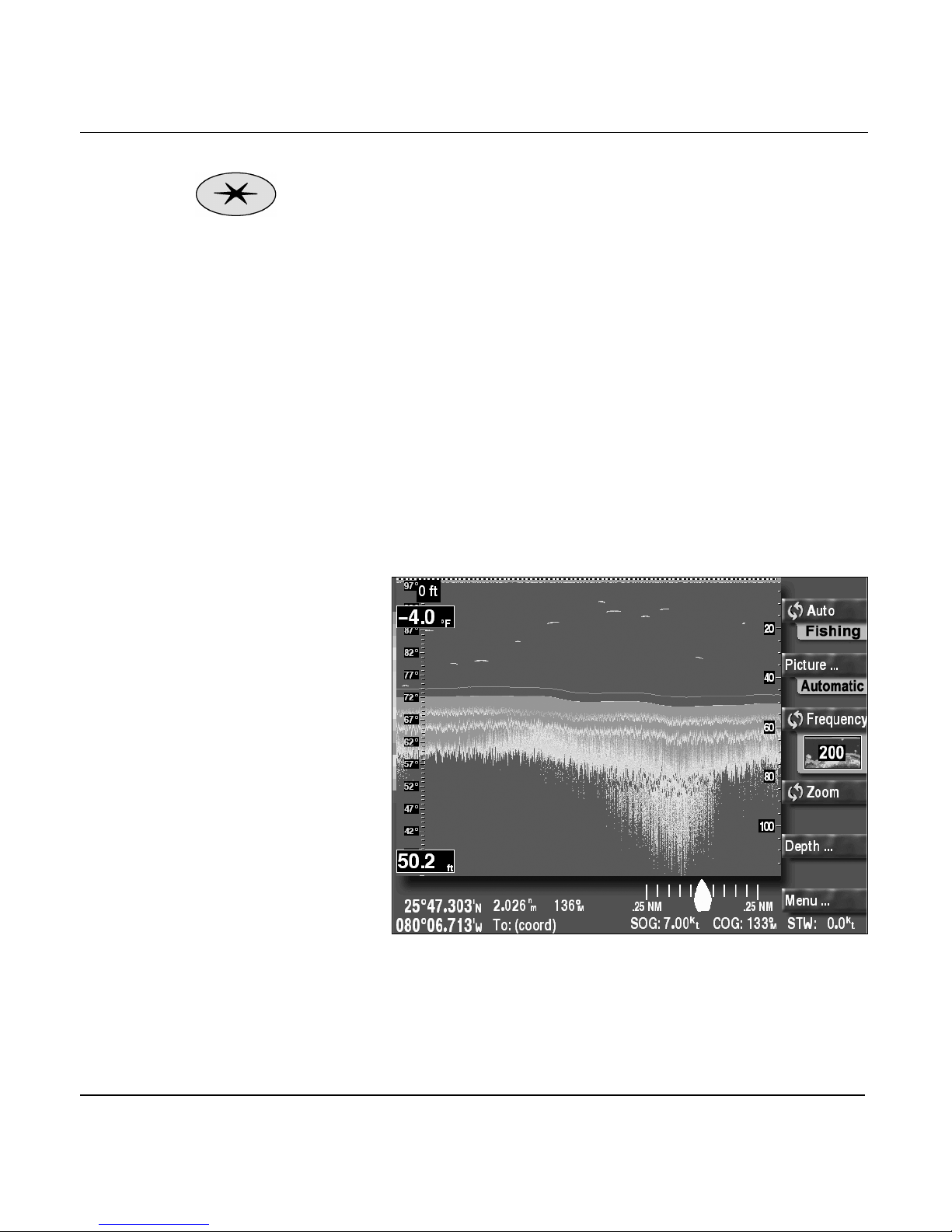
Chapter 3 - Using the Controls
STAR key
The STAR key controls five separate functions; each keypress
displays a separate screen in the following order:
1. Echo Sounder (if installed)
2. Alarms
3. Setup functions
4. Echo Sounder setup functions (if installed)
5. Service functions
Echo Sounder
The ECHO SOUNDER screen indicates the depth of the water
under the vessel, the position and depth of fish, and the
contours of the seabed. From this screen, you access all echo
sounder operations. For details about using the echo sounder,
see the Northstar 490 Echo Sounder Operations Manual
(GM490).
Alarms
The ALARMS screen shows any new alarms waiting to be
viewed and cleared; a history of old alarms already viewed and
961/962 Operations and Reference Manual, Rev. A Page 3-9
Echo sounder screen
Page 68
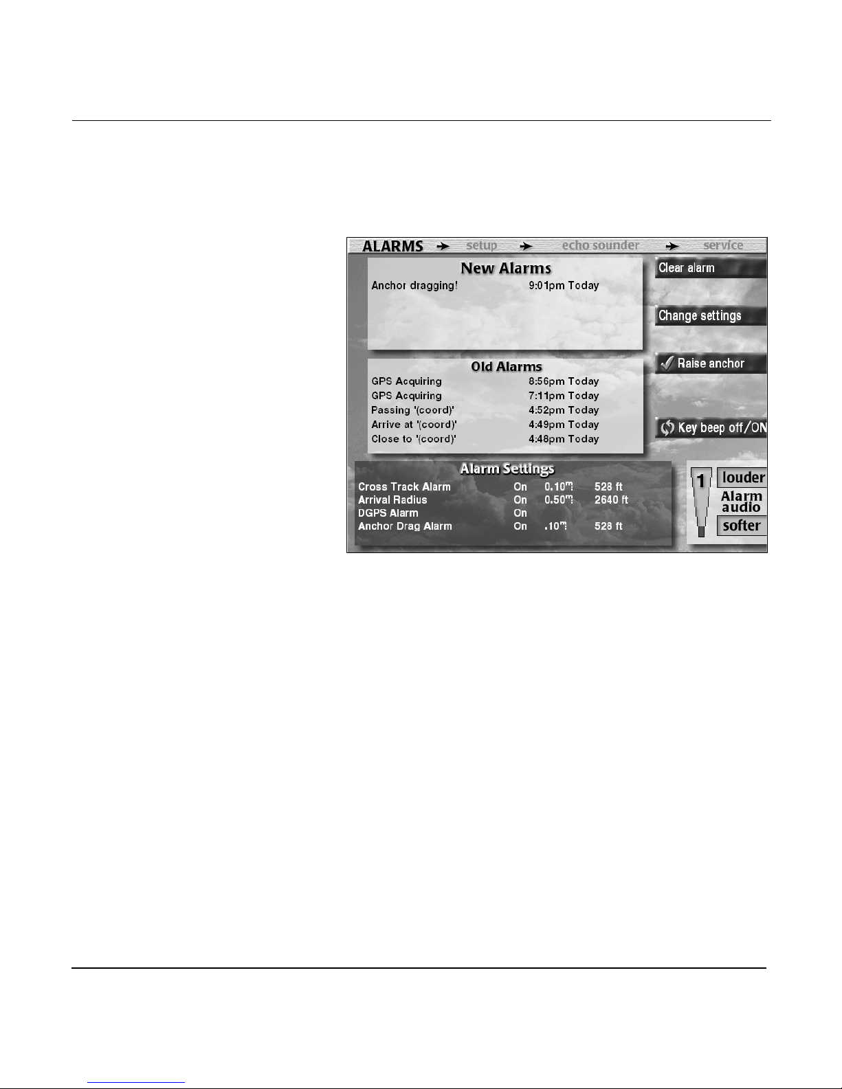
Chapter 3 - Using the Controls
cleared; current alarm settings (alarms turned on or off) and
distance settings (for example, a 0.15-nm waypoint arrival
radius); and the current sound level of the alarm audio using a
thermometer-style indicator.
Alarms screen
The ALARMS screen uses six menu keys—CLEAR ALARM,
CHANGE SETTINGS, DROP ANCHOR/RAISE ANCHOR, KEY
BEEP OFF/ON, LOUDER, and SOFTER—to control the alarm
functions:
•Use the CLEAR ALARM key to clear the newest alarm
after you’ve viewed the alarm message, and move the
alarm message to the old alarms list. Most alarms
automatically self-clear when the alarm condition is no
longer present, but you can use the CLEAR ALARM key
to manually clear most alarms, if desired. This key only
appears if there are new alarms present.
•Use the CHANGE SETTINGS key to turn an alarm on or
off, or to change the alarm distance.
•Use the DROP ANCHOR key to “drop” the anchor; use the
RAISE ANCHOR key to “raise” the anchor.
Page 3-10 961/962 Operations and Reference Manual, Rev. A
Page 69
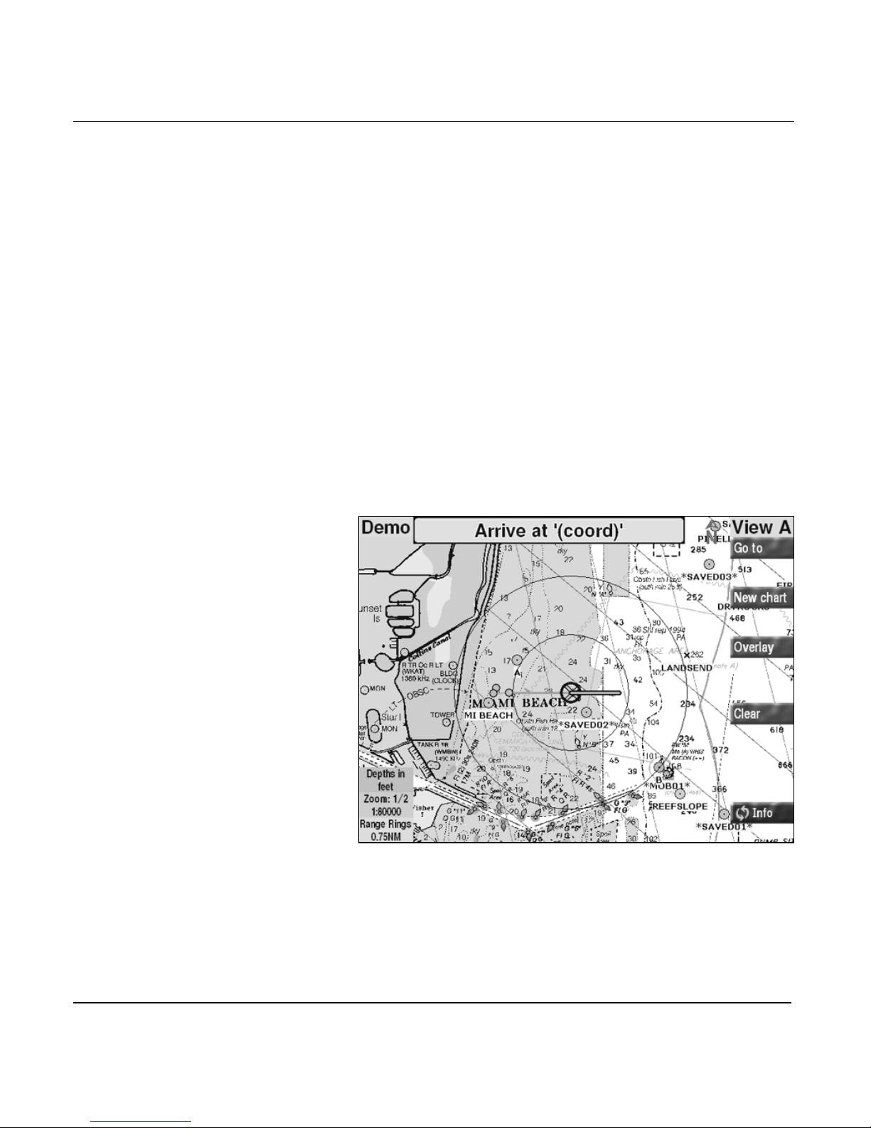
Chapter 3 - Using the Controls
•Use the KEY BEEP OFF/ON key to turn off the audio of
the keys—except for the MOB key and the SAVE key
(these keys will always beep).
•Use the LOUDER key to increase the volume of the alarm
audio.
•Use the SOFTER key to decrease the volume of the alarm
audio.
Alarms contain information you should read as soon as
possible, including such information as a dragging anchor, lost
GPS signals, or the upcoming arrival at a particular waypoint.
Alarms are displayed at the top of the CHART screen and at
the bottom of other screens, including the echo sounder
screens. They are accompanied by sound unless the audio is
turned off. Exceptions to this are the anchor drag and
avoidance points alarms, which are accompanied by a
somewhat louder beeping.
Even if you’re not actually looking at the display screen, the
alarm audio sounds, reminding you to check for alarm
messages.
961/962 Operations and Reference Manual, Rev. A Page 3-11
Chart-screen alarm message
Page 70
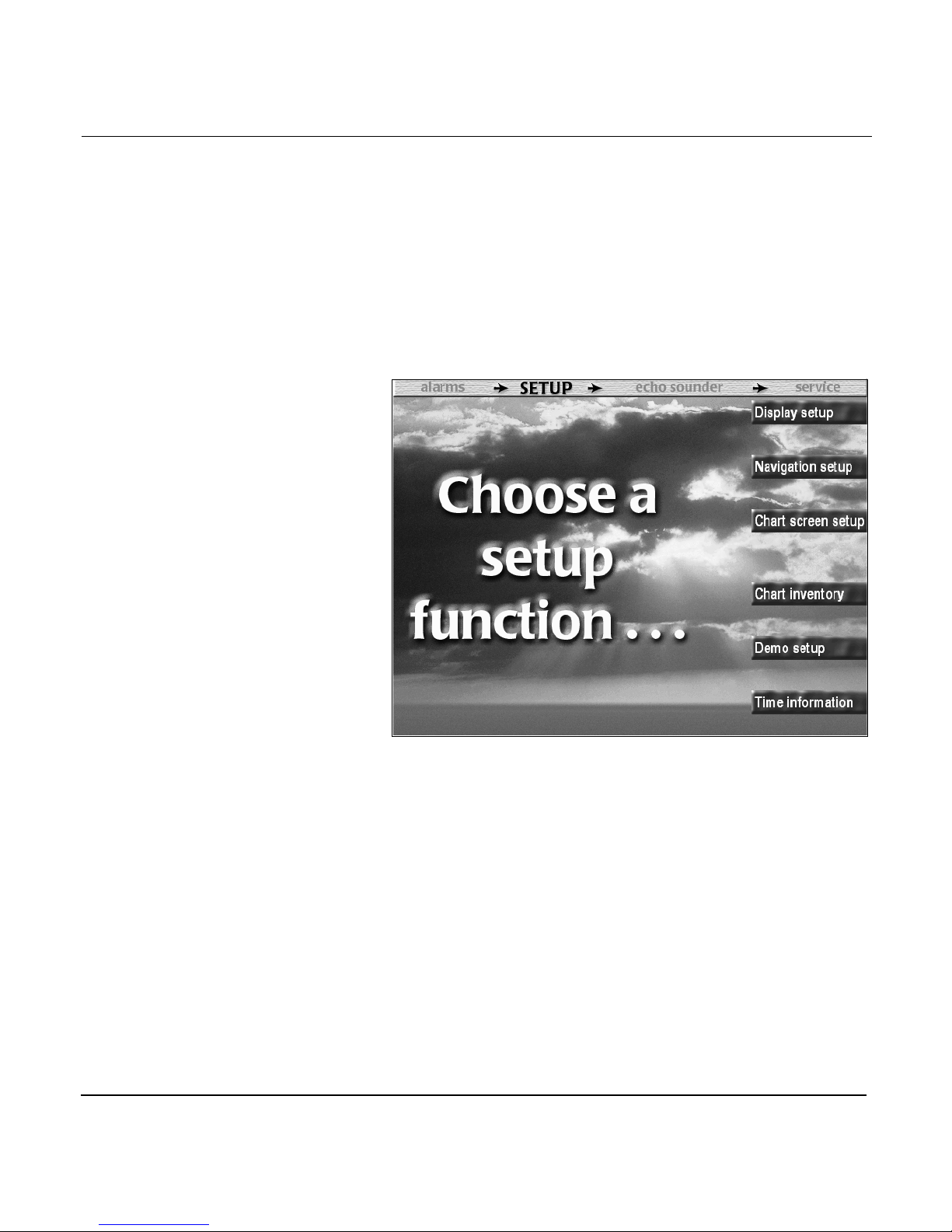
Chapter 3 - Using the Controls
For more about the alarm function, see “Understanding
alarms” starting on page 12-2.
Setup menu
The SETUP MENU screen offers six options to customize your
961/962, including display, navigation, and chart setup; and
functions to load/update/delete charts, set up demo mode, and
view time information.
Setup menu screen
The SETUP MENU screen uses six menu keys—DISPLAY
SETUP, NAVIGATION SETUP, CHART SCREEN SETUP,
CHART INVENTORY, DEMO SETUP, and TIME
INFORMATION—to control setup customization:
•Use the DISPLAY SETUP key to change the time zone
and the time-display format, XTE scale on both steering
screens, distance and speed units, tide-height units,
maximum number of *SAVEDXX* waypoints, and the
vessel’s owner identification message and password. For
more about these options, see “Changing the display
setup” starting on page 13-2.
Page 3-12 961/962 Operations and Reference Manual, Rev. A
Page 71

Chapter 3 - Using the Controls
•Use the NAVIGATION SETUP key to set the geodetic
datum reference to auto or manual (if set to manual,
choose from a list of 150 datums), preferred loran GRI,
automatic or manual waypoint switching, automatic or
manual calculation of magnetic variation (or else true
north), and calculation of distance, bearing, and XTE
using either a rhumb line or great circle. For more about
these options, see “Changing navigation setup” starting
on page 13-10.
•Use the CHART SCREEN SETUP key to set the display of
individual waypoint symbols, turn on or off the display of
waypoint names and waypoint symbols on the CHART
screen, control the CURSOR PAD sensitivity (advanced
feature), enable the ClearZoom feature, change the chart’s
orientation, set the length of the position predictor line,
show loran TDs on the CHART screen INFO BARs and the
CURSOR INFO BAR, and turn on or off the display of
range rings, the distance scale bar, past trip legs, and a
chart-update region on the CHART screen. For more
about all of these options, see “Changing the chart setup”
starting on page 13-24.
•Use the CHART INVENTORY key to load/update charts,
delete charts from the database, and access all
HCRF-specific functions. For more about these functions,
see “Loading, updating, and deleting charts” starting on
page 13-35.
•Use the DEMO SETUP key to invoke the demo function
for training purposes, practicing for an upcoming trip, or
just looking ahead to an anticipated destination. You can
set up demo to simulate NMEA/PPNM output for 10
minutes. For more about these functions, see “Using demo
mode” starting on page 13-69.
•Use the TIME INFORMATION key to show the date and
time (based on the local time zone), and time of today’s
sunrise and sunset for the current vessel position. For
details, see “Viewing the time information screen” starting
on page 13-72.
961/962 Operations and Reference Manual, Rev. A Page 3-13
Page 72
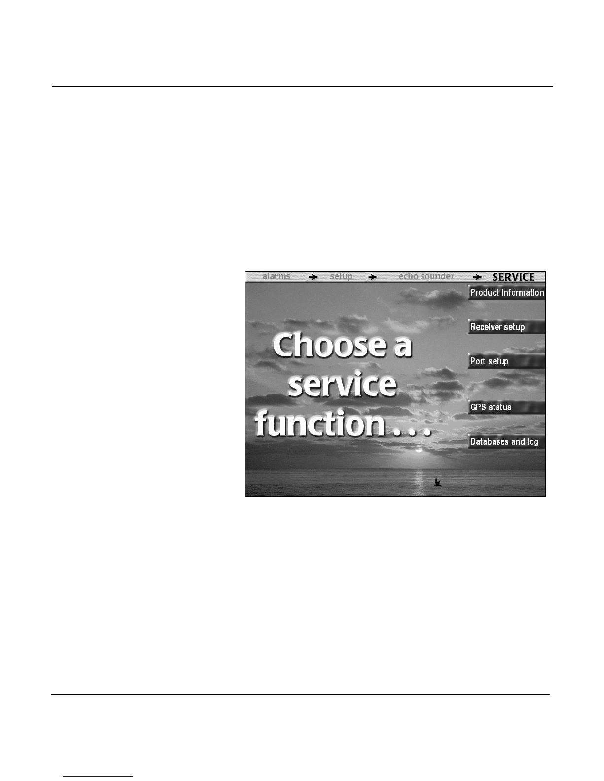
Chapter 3 - Using the Controls
Echo sounder setup menu
For details about setting up the 490 Echo Sounder, see the
Northstar 490 Echo Sounder Installation Manual (GM490).
Service menu
The SERVICE MENU screen uses five menu keys—PRODUCT
INFORMATION, RECEIVER SETUP, PORT SETUP, GPS
STATUS, and DATABASES AND LOG—to control service
functions:
Page 3-14 961/962 Operations and Reference Manual, Rev. A
Service menu screen
•Use the PRODUCT INFORMATION key to view such
information as the serial number and software revision of
the control head(s) and processor, the self-test status and
software revision of the GPS and beacon receivers, and
the amount of memory in the processor. For more about
viewing product information, see “Viewing product
information” starting on page 14-2.
•Use the RECEIVER SETUP key to set the time for GPS
speed averaging, set the lowest usable satellite elevation,
view the version of the beacon receiver, turn the DGPS
Page 73
Chapter 3 - Using the Controls
system on or off, and to manually set the beacon
receiver’s frequency and baud rate. For more about these
options, see “Configuring the receiver” starting on page
14-4.
•Use the PORT SETUP key to configure the four I/O ports
as required for any devices that you’ll interface to the
961/962, and to enable Pulses Per Nautical Mile (PPNM).
For more technical information about these options, see
the Northstar 961/962 GPS Chart Navigator Installation
Manual. Here’s where you enable the Northstar 490 so
you can view the echo sounder screens. For more
information, see the Northstar 490 Echo Sounder
Installation Manual (GM491).
•Use the GPS STATUS key to view a display of all available
satellites, including their signal strength and your
expected accuracy, as well as the frequency, baud rate,
and status of DGPS transmitters (961XD/962XD only). For
more about viewing GPS and DGPS information, see
“Viewing GPS status” starting on page 14-9.
STEER key
•Use the DATABASES AND LOG key to save or restore the
waypoints/routes and the user preferences (display,
navigation, chart, receiver, and port-setup options), and to
save log data when troubleshooting the system. For
details, see “Saving and restoring databases and logs”
starting on page 14-10.
Use the STEER key to access either of two screens that help
you steer precisely along your desired track to your active
waypoint. As you use them, you’ll probably develop a
preference for one or the other. Each press of the STEER key
retrieves one of two separate screens as follows:
• traditional steering indicator with numeric data
• three-dimensional (3-D) graphical navigation with
numeric data
Whenever you press the STEER key, you’ll always return to
the steering screen you were last using; press the STEER key
again to switch to the other screen.
961/962 Operations and Reference Manual, Rev. A Page 3-15
Page 74
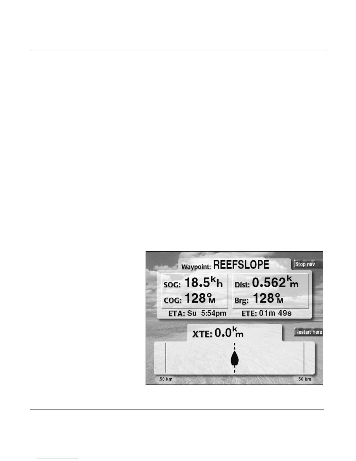
Chapter 3 - Using the Controls
Both steering screens use two menu keys—STOP NAV and
RESTART HERE—to control steering functions:
•Use the STOP NAV/RESUME NAV key to stop navigation
to a waypoint, or resume navigation when desired.
“Stopping” navigation means that the 961/962 turns off
waypoint messages and sequencing. For details about
stopping navigation, see “Stopping navigation” starting on
page 11-15.
•Use the RESTART HERE key to restart the track line to
the active waypoint (XTE becomes zero) so that your
present position becomes the initial track point (your
vessel will subsequently follow any remaining waypoints
in the trip). For details about restarting the track, see
“Restarting the track” starting on page 10-19.
Traditional steer screen
The traditional STEER screen shows your active waypoint, if
any; distance and bearing from your present position to the
active waypoint; XTE (shown numerically, and graphically at
the lower part of the screen); SOG and COG; and ETA and ETE.
Page 3-16 961/962 Operations and Reference Manual, Rev. A
Traditional steer screen
Page 75
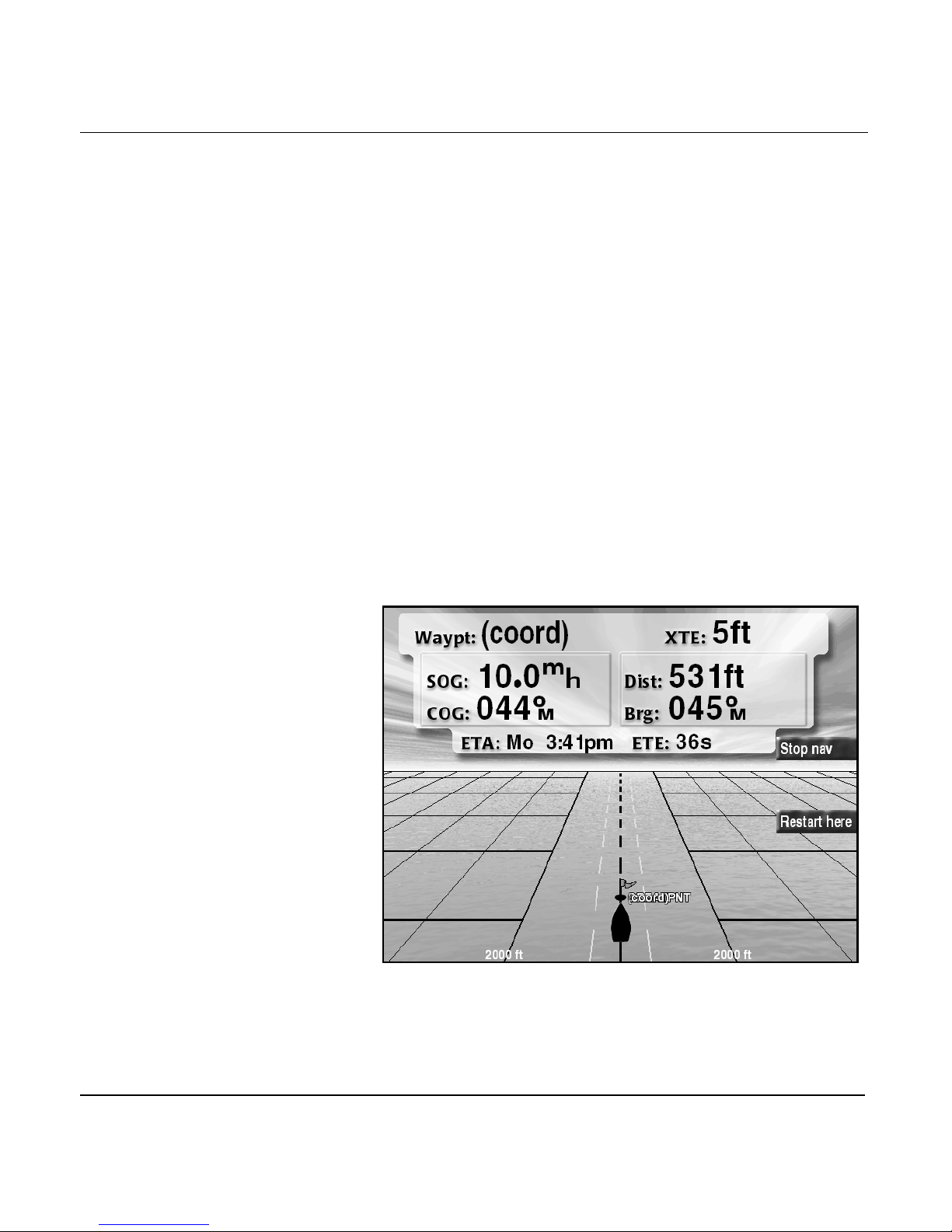
Chapter 3 - Using the Controls
Three-dimensional (3-D) steer screen
The 3-D STEER screen shows a panoramic 3-D view with
graphical and numerical data. Graphically, the 3-D STEER
screen shows your active waypoint, if any (shown with a green
flag, or red if it’s an MOB waypoint); XTE; nearby trip and route
waypoints (shown with blue flags), and avoidance points
(shown as red circles) all in relation to your desired track (the
dashed center line); and distance and bearing from your
present position to the active waypoint. SOG, COG, ETA, and
ETE are shown numerically.
If you’re navigating to a waypoint, the 3D STEER screen
displays your vessel on or near your desired track line,
according to your XTE. If you aren’t navigating to a waypoint,
the 3D STEER screen still shows a course-up view of nearby
waypoints.
You can press the IN and OUT keys to zoom in and out on the
3-D STEER screen.
For more about the steering function, see “Steering to a
waypoint” starting on page 10-2.
961/962 Operations and Reference Manual, Rev. A Page 3-17
3-D steer screen
Page 76
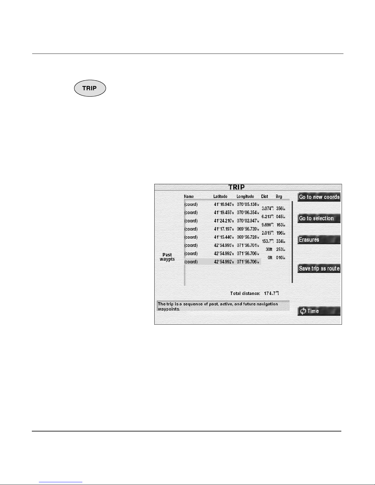
Chapter 3 - Using the Controls
TRIP key
A trip is a sequence of
waypoints, including
past, active, and future
waypoints.
Use the TRIP key to record today’s trip as well as to establish
future waypoints in the trip.
With the trip function, the 961/962 automatically records
every waypoint and saved point of today’s trip, and lets you
plan future parts of your trip by adding a series of waypoints,
or even routes, to this trip.
Press the TRIP key to display a list of past, active, and future
waypoints with their lat/lon coordinates, and for past
waypoints, the actual time of arrival as day and date or day
and time, as well as distance and bearing between points and
the total trip distance; and for active and future waypoints,
ETA as day and date or day and time.
By pressing the CURSOR PAD up and down, you can see all
past and future waypoints.
The TRIP screen has six menu keys—GO TO NEW COORDS,
GO TO SELECTION, ERASURES, SAVE TRIP AS ROUTE,
STOP NAV/RESUME NAV (not shown if no active waypoint),
and DATE-DIST/BRG-TIME—that control the trip functions.
Page 3-18 961/962 Operations and Reference Manual, Rev. A
Trip screen
Page 77

Chapter 3 - Using the Controls
Use the GO TO NEW COORDS key to:
• put new points in the trip (go to them now or add them to
the end of your trip)
Use the GO TO SELECTION key to:
• re-use existing points in the trip (active, past, or future
points)
Use the ERASURES key to:
• remove points from the trip (all points or only selected
ones)
Use the SAVE TRIP AS ROUTE key to:
• save the trip as a permanent route
Use the STOP NAV/RESUME NAV key (not shown if there isn’t
an active waypoint) to:
• stop navigation alarms, waypoint sequencing, and
autopilot control, or else resume
WAYPTS/ROUTES
key
Use the DATE-DIST/BRG-TIME key to:
•switch the ARRIVAL column of the trip list between day
and time of arrival, day and date of arrival, and distance
and bearing between trip points along with the total trip
distance
For in-depth information about the trip function, see “Using
the Trip Function” starting on page 11-1.
Pressing the WAYPTS/ROUTES key lets you create new
waypoints, routes, tracks, and avoidance points; access, sort,
and edit lists of stored waypoints, routes, tracks, and avoidance
points; navigate to a stored waypoint; and follow a stored
route.
NOTE:
You can also create and store waypoints and routes directly from
the CHART
CHART
on page 6-8. For information about creating routes from the
CHART
page 8-10.
screen. For more about creating waypoints from the
screen, see “Creating a new waypoint graphically” starting
screen, see “Creating a route as you travel” starting on
961/962 Operations and Reference Manual, Rev. A Page 3-19
Page 78
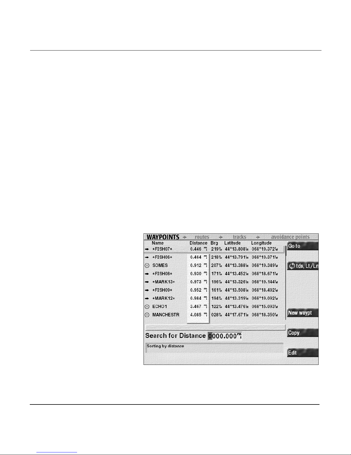
Chapter 3 - Using the Controls
A waypoint is a
specific position
defined by either its
lat/lon, TDs, or
distance and bearing
from some position fix.
The WAYPTS/ROUTES key controls four functions; each
keypress displays a separate screen in the following order:
1. Waypoints
2. Routes
3. Tracks
4. Avoidance points
On these list screens, you can select each waypoint, route,
track, or avoidance point by pressing the up and down arrows
of the CURSOR PAD; the currently selected waypoint, route,
track, or avoidance point is indicated by a horizontal stripe.
Waypoints screen
The WAYPOINTS screen lists all your stored, named waypoints
by symbol; name; distance and bearing; and lat/lon or TDs (the
distance and bearing fields are completely blank if there’s no
position fix). Until you store user-defined waypoints in the
database, the WAYPOINTS screen will be blank.
Page 3-20 961/962 Operations and Reference Manual, Rev. A
Waypoints screen
Page 79

Chapter 3 - Using the Controls
By pressing the CURSOR PAD left or right, you can sort the
waypoint list by each column (selected columns are
highlighted with a vertical stripe):
• a sort by the symbol column (not titled) lists waypoints by
similar symbols
•a sort by the NAME column yields an alphabetical list
•a sort by the DISTANCE or BRG (bearing) columns lists
waypoints in order of distance or bearing from your
present position
You can also search the list for a particular waypoint by
entering the first few characters of the category you’re sorting
by.
The WAYPOINTS screen has five menu keys—GO TO, TDS,LT/
LN, NEW WAYPT, COPY, and EDIT—that control waypoint
functions.
Use the GO TO key to:
• go directly to the selected waypoint (erases the future part
of your trip)
• add the selected waypoints to the end of your current trip
(if you’re already past the last waypoint, you’ll start
navigating along the newly entered leg)
Use the TDS,LT/LN key to:
• switch between displaying lat/lon coordinates or TDs
Use the NEW WAYPT key to:
• add a new waypoint to the list
Use the COPY key to:
• make a new waypoint by editing a copy of an existing one
Use the EDIT key to:
•edit a waypoint
•erase a waypoint
For in-depth information about waypoints, see “Creating
Waypoints” starting on page 6-1.
961/962 Operations and Reference Manual, Rev. A Page 3-21
Page 80
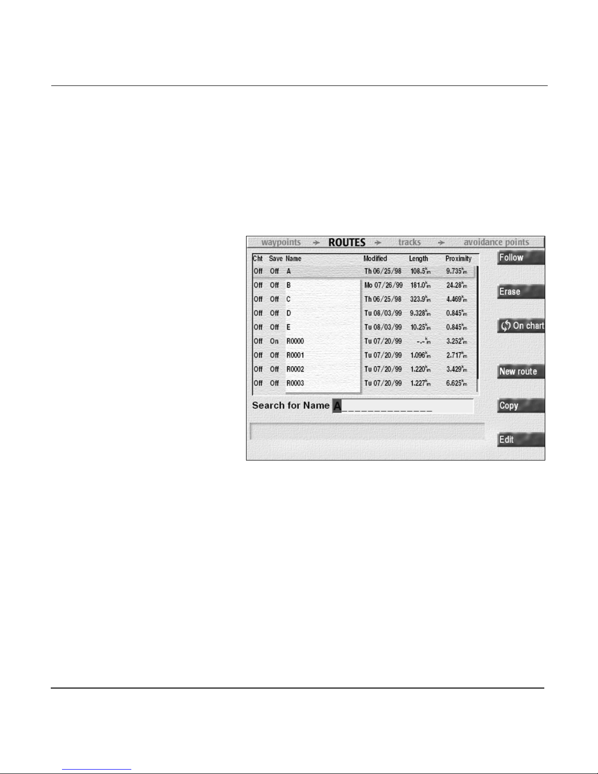
Chapter 3 - Using the Controls
Routes screen
A route is a group of two or
more pre-defined waypoints
that form a connected path
between specific locations.
A leg is the line, or path,
between any two waypoints
in a route.
The ROUTES screen lists all your stored routes sorted by
whether a route is marked for display on the CHART screen;
whether a route is marked to accept SAVE keypresses; name;
date the route was last modified; total distance covered by
each route (length); and proximity (distance from your present
position). Until you store user-defined routes in the database,
the ROUTES screen will be blank.
Routes screen
By pressing the CURSOR PAD left or right, you can sort the
route list by each column (selected columns are highlighted
with a vertical stripe):
•a sort by the CHT column (means the route is marked for
display on the CHART screen) places that route at the top
•a sort by the SAVE column places that route at the top
•a sort by the NAME column lists routes alphabetically
•a sort by the MODIFIED column (date last modified) places
most recent dates at the top
•a sort by the LENGTH column places the shortest routes
at the top
Page 3-22 961/962 Operations and Reference Manual, Rev. A
Page 81

Chapter 3 - Using the Controls
•a sort by the PROXIMITY places routes closest to your
present position at the top
You can also search the list for a particular route by entering
the first few characters of the route’s name.
The ROUTES screen has six menu keys—FOLLOW, ERASE,
ON CHART, NEW ROUTE, COPY, and EDIT—that control the
route function.
Use the FOLLOW key to:
• follow the selected route (first you choose the starting
waypoint) in a forward or reverse direction
• join a selected leg of the route, and follow the remainder
of the route, in a forward or reverse direction
• add the selected route—starting with a selected
waypoint—to the end of your trip, in a forward or reverse
direction
Use the ERASE key to:
• delete the selected route
Use the ON CHART key to:
• mark a route for display on the CHART screen (you can
display only one route on the CHART screen at a time)
Use the NEW ROUTE key to:
• create a new route from the list of waypoints stored in the
database, and graphically view the new route as you
create it
• create a new route by adding waypoints to this route
when you press the SAVE key
Use the COPY key to:
• make a new route by editing a copy of an existing,
selected route (choose the normal order or reverse)
Use the EDIT key to:
• add or delete an existing route’s waypoints, or change its
name
961/962 Operations and Reference Manual, Rev. A Page 3-23
• mark this route to accept SAVE keypresses (adds
waypoints to this route when you press the SAVE key)
Page 82
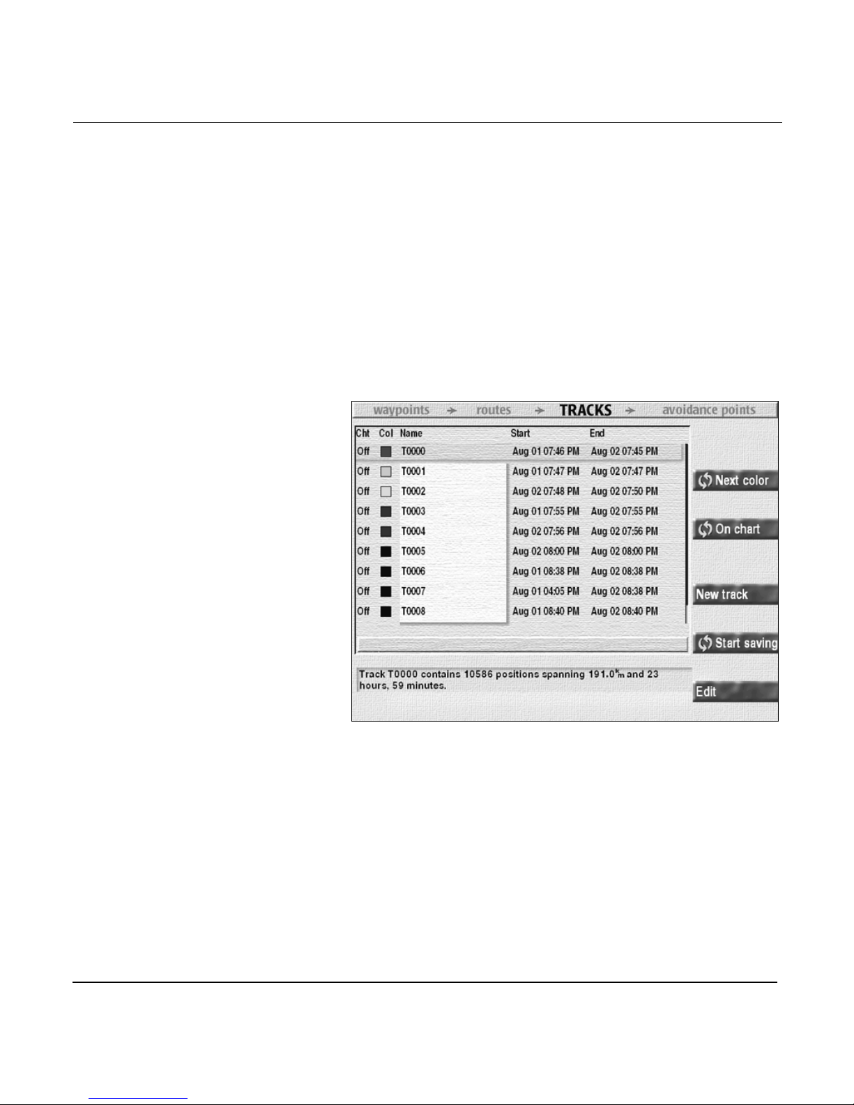
Chapter 3 - Using the Controls
For information about routes, see “Creating Routes” starting
on page 8-1.
Tracks s creen
A track is a sequence of
position measurements
that’s defined by actually
travelling from point A to
point B. That is, a track is
a continuous record—not
individual waypoints—of
the path your vessel has
travelled.
The TRACKS screen lists your stored tracks by whether the
track is marked for display on the CHART screen; color (for
CHART screen display); name; start date and time of the first
track point; and end date and time of the last track point. A
description of the selected track is also displayed. Until you
store user-defined tracks in the database, the TRACKS screen
will be blank.
By pressing the CURSOR PAD left or right, you can sort the
track list by each column (selected columns are highlighted
with a vertical stripe):
Page 3-24 961/962 Operations and Reference Manual, Rev. A
Tracks screen
•a sort by the CHT column (marked for display on the
CHART screen) places that track at the top
•a sort by the COL column (color) groups same colors
together
Page 83

Chapter 3 - Using the Controls
•a sort by the NAME column lists tracks numerically (if
named by number), then alphabetically
•a sort by the START or END columns lists tracks by most
recent date and time
The TRACKS screen has five menu keys—NEXT COLOR, ON
CHART, NEW TRACK, START SAVING, and EDIT—that
control the track function (if there aren’t any defined tracks,
this screen is empty).
Use the NEXT COLOR key to:
• select another color for the selected track
Use the ON CHART key to:
• mark a track for display on the CHART screen or hide the
track
Use the NEW TRACK key to:
• define a new track by picking a start time and end time
An avoidance point is
a specific position
defined by its radius,
and either its lat/lon, or
TDs, or distance and
bearing from some
position fix.
Use the START SAVING key to:
• start saving a new track immediately, then stop saving at
any time
Use the EDIT key to:
• change the description or name of an existing track
• permanently erase a track
For information about tracks, see “Introducing tracks” starting
on page 9-2.
Avoidance points screen
The AVOIDANCE POINTS screen lists all your stored, named
avoidance points by radius; name; distance and bearing; and
lat/lon or TDs (the distance and bearing fields are blank if
there’s no position fix). Until you store user-defined avoidance
points in the database, the AVOIDANCE POINTS screen will be
blank.
961/962 Operations and Reference Manual, Rev. A Page 3-25
Page 84
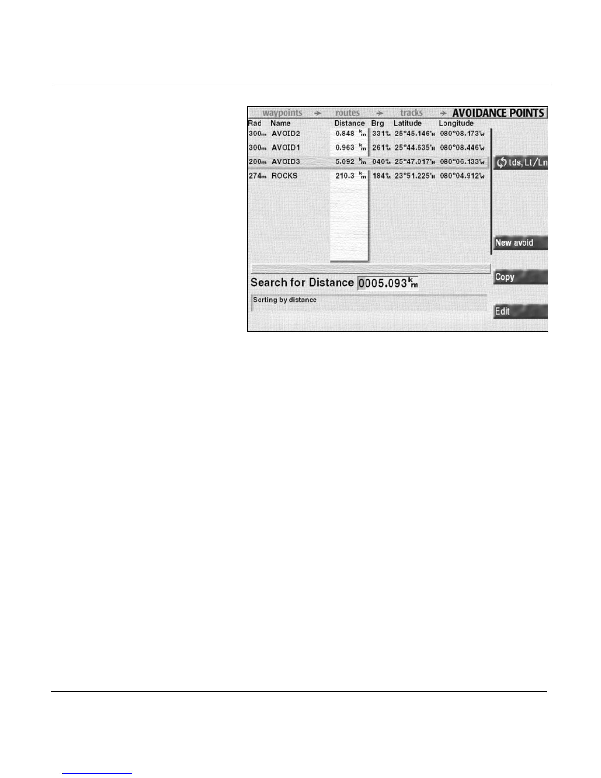
Chapter 3 - Using the Controls
Avoidance points screen
By pressing the CURSOR PAD left or right, you can sort the
avoidance point list by each column (selected columns are
highlighted with a vertical stripe):
•a sort by the RAD (radius) column lists avoidance points
by radius
•a sort by the NAME column yields an alphabetical list
•a sort by the DISTANCE or BRG (bearing) columns lists
avoidance points in order of distance or bearing from
your present position
You can also search the list for a particular avoidance point by
entering the first few characters of the category you’re sorting
by.
The AVOIDANCE POINTS screen has four menu keys—TDS,LT/
LN, NEW AVOID, COPY, and EDIT—that control avoidance
point functions.
Use the TDS,LT/LN key to:
• switch between displaying lat/lon coordinates or TDs
Page 3-26 961/962 Operations and Reference Manual, Rev. A
Page 85
Brightness key
Chapter 3 - Using the Controls
Use the NEW AVOID key to:
• add a new avoidance point to the list
Use the COPY key to:
• make a new avoidance point by editing a copy of an
existing one
Use the EDIT key to:
• edit an avoidance point
• erase an avoidance point
For information about avoidance points, see “Creating
Avoidance Points” starting on page 7-1.
Controlling
LCD-screen
brightness
To adjust the screen for the current lighting conditions, press
the BRIGHTNESS key, which is the double-arrow key located
on the upper left-hand side of the 961/962. Press the top arrow
to brighten the screen, or the bottom arrow to darken the
screen.
At high brightness, the fluorescent tubes illuminating the
screen slowly dim after several thousand hours of use. If you
use the 961/962 for several hours each day, try to keep the
lighting level low when you don’t actually need it (for
example, during twilight or nighttime hours). Occasional
users—once a week or less—don’t need to worry about keeping
the lighting level low.
Producing the high brightness needed for sunlight visibility
creates heat within the control head. When used during hot
sunlit conditions, the 961/962 may automatically protect itself
from overheating by lowering its screen brightness. If this
situation occurs, it’s perfectly acceptable to increase the
brightness whenever necessary—the screen will dim again, if
necessary.
If you don’t touch any key on the control head for one hour or
more, its LCD screen automatically dims to half its maximum
brightness (based on its current brightness), if necessary. If
you press any key at any time, the display automatically
961/962 Operations and Reference Manual, Rev. A Page 3-27
Page 86
Chapter 3 - Using the Controls
SAVE key
restores its previous brightness level. This function helps
maintain the integrity of the display screen and reduce power
consumption when the 961/962 is on for many hours at a
time.
The SAVE key instantly saves your vessel’s position—at any
time, at any screen, during any function. For example, if you’re
editing data on the NAVIGATION SETUP screen when you
press the SAVE key, you’ll still obtain the VESSEL POSITION
dialog box that always follows SAVE keypresses. Pressing the
SAVE key temporarily saves your vessel’s position; at a later
time, you can rename this *SAVEDXX* waypoint to save it
permanently. Pressing the SAVE key lets you save a new
waypoint (as a single waypoint or as multiple waypoints in a
route), or add your vessel’s position to the end of the
previously designated route.
MOB key
For details about using the SAVE key to save your vessel’s
position as a waypoint, see “Creating a new waypoint at the
vessel’s position” starting on page 6-11.
For details about using the SAVE key to save your vessel’s
position as part of a new route, see “Creating a route as you
travel” starting on page 8-10.
Pressing the MOB key the first time instantly saves your
position as a Man Overboard (MOB) waypoint. The MAN
OVERBOARD dialog box appears, and you now have five
seconds to press CANCEL if you accidentally pressed MOB.
Unless you press CANCEL, the CHART screen is automatically
displayed (no matter what screen you were previously
viewing), and navigation is provided directly to the MOB
coordinates. Even if you press CANCEL, an MOB waypoint is
still created on the CHART screen, although navigation to this
point won’t be provided.
Page 3-28 961/962 Operations and Reference Manual, Rev. A
Page 87
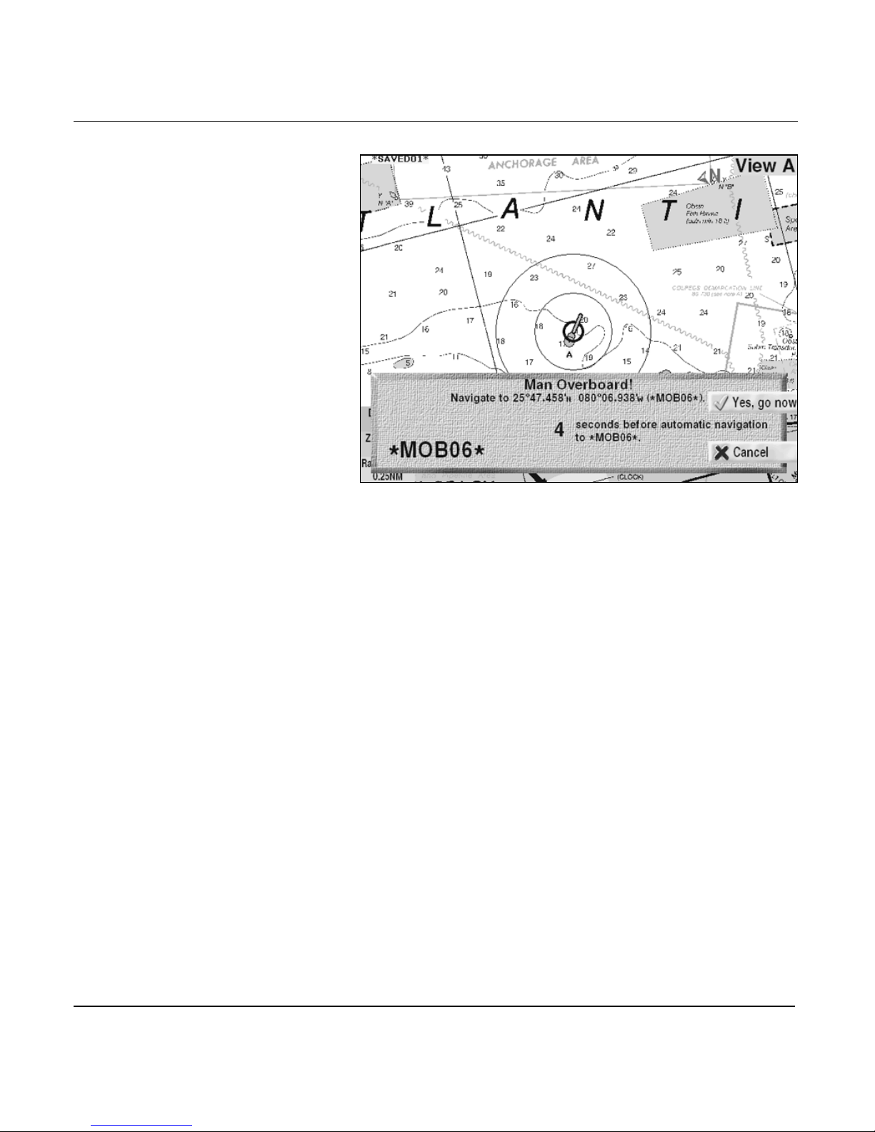
Chapter 3 - Using the Controls
Man overboard dialog box
Your position is saved and displayed on the CHART screen as a
waypoint with a symbol called *MOBXX*: The MOB position
has immediately become your active waypoint. When
navigating to an *MOBXX* waypoint, the chart’s zoom level
will automatically be set to its native level (1/1).
961/962 Operations and Reference Manual, Rev. A Page 3-29
Page 88
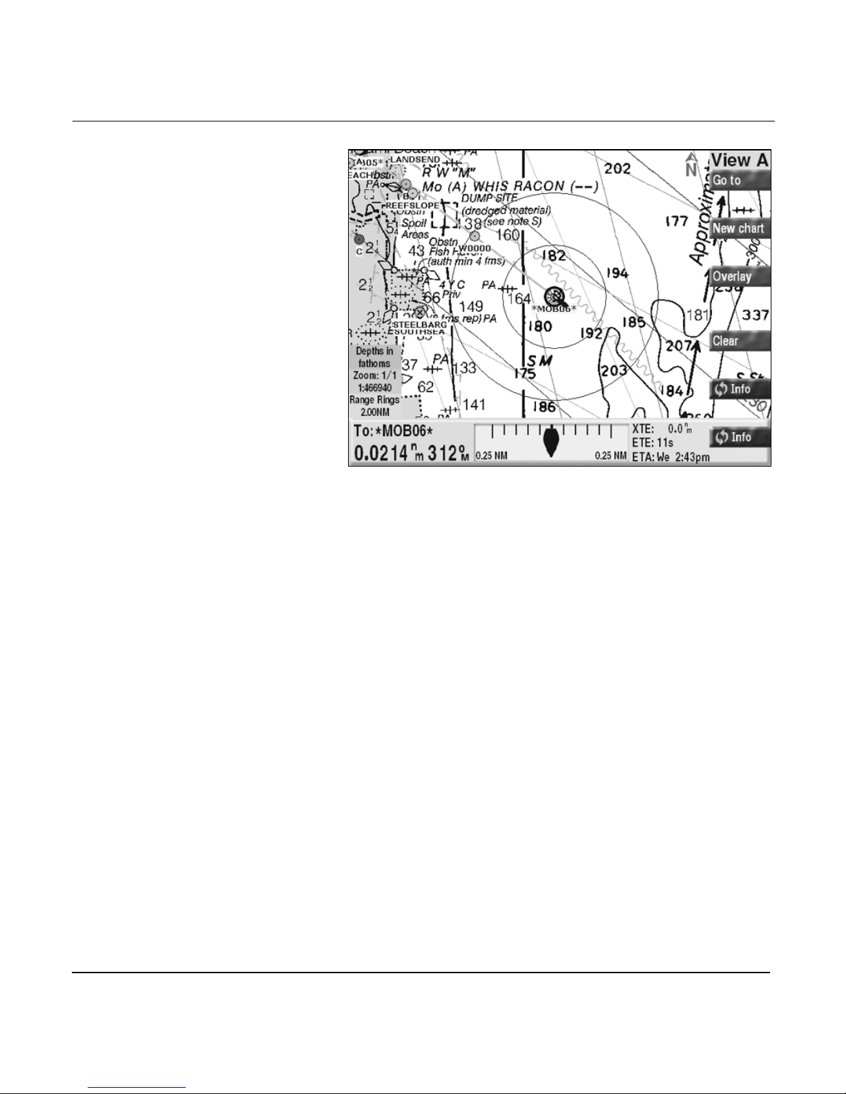
Chapter 3 - Using the Controls
Chart screen with *MOB06* waypoint
After the MOB keypress, the CHART screen INFO BAR
automatically appears, even if you haven’t pressed the INFO
key. This INFO BAR shows the *MOBXX* waypoint as your
active waypoint. If you press the WAYPTS/ROUTES key, you’ll
see the *MOBXX* waypoint in the list, and *MOBXX* waypoints
are also displayed on the 3-D STEER, STEER, and TRIP
screens.
If you press the MOB key a second time—before you arrive at
this first *MOBXX* waypoint—you’ll have to press the YES, GO
NOW key to confirm, because a second MOB keypress would
save your latest position and make this your active waypoint
instead.
If you’ve stopped navigation, it is automatically resumed as
soon as you press the MOB key.
Page 3-30 961/962 Operations and Reference Manual, Rev. A
Page 89
Chapter 3 - Using the Controls
IN and OUT keys
Cursor pad
The cursor pad’s
purpose
CAUTION!
Each press of the IN key zooms in to double the chart scale;
each press of the OUT key zooms out to halve the chart scale.
The CURSOR PAD is located in the lower right-hand corner,
and has two similar functions; how you use the CURSOR PAD
depends on what function you’re performing on the CHART
screen or other screens. If you’re navigating on the CHART
screen, the CURSOR PAD is used to move the on-screen
square cursor to designate a position on the chart. If you’re at
other screens, however, the CURSOR PAD is used to highlight
different selections of data.
Some autopilots try to steer your vessel according
to any bearing changes made by the 961/
962—regardless of the severity of the change.
Other autopilots automatically disengage when a
severe or abrupt turn is required. For information
about implementing MOB while using an autopilot,
refer to your autopilot’s manual.
Using the cursor
pad on the chart
screen
961/962 Operations and Reference Manual, Rev. A Page 3-31
On the CHART screen, you can move the CURSOR PAD in an
up-to-down, left-to-right, or diagonal direction. You can move
the cursor diagonally by pressing between any two of its arrow
indicators. The longer you hold the CURSOR PAD, the faster
the cursor moves. To carefully move the cursor small
distances on the CHART screen, the easiest way is to place
your thumb in the center of the CURSOR PAD and gently
push left, right, up, or down. This method gives much finer
control than poking at the edge of the CURSOR PAD.
Page 90
Chapter 3 - Using the Controls
Using the cursor
pad on other
screens
Arrow keys
On other screens, you move the CURSOR PAD in an
up-to-down (vertical) and left-to-right (horizontal) direction to
select data. For example, at the WAYPOINTS screen, you press
the CURSOR PAD to highlight different waypoints comprising
the waypoint list: First press the WAYPTS/ROUTES key to
view the WAYPOINTS screen, then press the up and down
arrows of the CURSOR PAD to highlight waypoints. If you
now want to edit this highlighted waypoint, press the EDIT
key, and you’ll see the red cursor flashing in the NAME field.
From this point, press the CURSOR PAD left and right to move
the cursor from field to field.
The alphanumeric KEYPAD contains a LEFT ARROW key and
a RIGHT ARROW key, which are used while entering data to
move the flashing cursor to the character you want to change.
For example, if you make a mistake when entering lat/lon
coordinates or waypoint and route names, press the LEFT
ARROW key to move the cursor—a flashing red box that
represents the place at which the next typed character will
appear—back to a previous character. Use the RIGHT ARROW
key to move the cursor to the right.
The arrow keys also have other uses on the CHART screen:
The most important one occurs after you’ve pressed the
CURSOR PAD, and you’ve selected a particular object that has
multiple meanings; press the LEFT ARROW or RIGHT ARROW
to cycle through the selection of several possible objects
selected by the cursor.
Other uses include selecting time and date for tides, currents,
and tracks. When the arrow keys are meant to be used in this
way, a small picture of the arrow keys is displayed on the
screen.
Page 3-32 961/962 Operations and Reference Manual, Rev. A
Page 91

Menu keys
Chapter 3 - Using the Controls
Use the six MENU keys—located in a vertical row on the right
of the display screen—for a variety of functions. Each key’s
function depends specifically on which screen you’re
displaying; each key’s current function is shown right on the
screen.
961/962 Operations and Reference Manual, Rev. A Page 3-33
Page 92

Chapter 3 - Using the Controls
Page 3-34 961/962 Operations and Reference Manual, Rev. A
Page 93

4
Understanding the Chart Screen
Understanding electronic charts . . . . . . . . . . . 4-2
Understanding the chart screen . . . . . . . . . . . 4-2
Displaying your vessel’s position on a chart 4-4
Functions performed at the chart screen . . . 4-4
Using the cursor on the chart screen . . . . . . 4-17
T
his chapter explains the 961/962’s electronic chart, the
chart views and their menu keys, and vessel and cursor
functions.
961/962 Operations and Reference Manual, Rev. A Page 4-1
Page 94

Chapter 4 - Understanding the Chart Screen
Understanding electronic charts
The electronic charts have been scanned directly from the
official paper charts. When used carefully, electronic charts
can open up a whole new world of accuracy and simplicity.
However, don’t let yourself become overly confident: Always
be cautious! The captain is responsible for cross-checking the
system against other sources of navigation data.
Moving between
charts
Chart scale
As your vessel moves from one area to another, the 961/962
automatically changes from one chart to another, taking your
chart scale and current zoom level into account. Remember
that the level of detail may vary from chart to chart. If you
move from a highly detailed chart to a less detailed one, you’ll
probably see a sudden change in the detail shown on the
screen, just as if you’d changed from one paper chart to
another.
At the lower left-hand side of the CHART screen is the chart
scale box, which shows the chart magnification. A display of 1/
1 indicates the largest magnification at which you can display
the current chart. As you zoom out, this number changes to 1/
2, 1/4, 1/8, and so on.
Understanding the chart screen
Chart orientation
The 961/962 displays charts with the orientation that you
specify. You can rotate the charts shown on the CHART
screen to any of the following viewing angles:
Page 4-2 961/962 Operations and Reference Manual, Rev. A
• CHART up (the orientation of the original paper chart;
north could be up, down, left, right, or any angle in
between; this is the default setting)
• COURSE up (the orientation of your true course during
the last few seconds, as determined by the GPS receiver)
• LEG up (the orientation of your desired track when
navigating, on a leg-by-leg basis, which provides a more
stable display than course-up)
Page 95

N
Chapter 4 - Understanding the Chart Screen
• NORTH up (usually the same as chart-up, but rotates any
charts that were originally skewed to fit a particular
coastline or harbor, so that true north is up on the CHART
screen)
A north-pointing directional arrow is displayed in the upper
right corner of the screen, indicating each chart’s orientation.
The plotter grid, available when there isn’t a chart for your
particular area, is always oriented in the north-up direction.
For details about using the CHART SETUP screen to change a
chart’s orientation, see “Chart orientation” starting on page
13-28.
Menu keys
Zooming in and out
on the chart screen
Both of the chart views have six menu keys—GO TO, NEW
CHART, OVERLAY, CLEAR, and two INFO keys; collectively,
these keys control a range of chart navigation functions. For a
complete description of these keys, see “Chart-view menu
keys” starting on page 3-6.
Zoom levels
Press the IN key to zoom in for a closer look at the area either
around your vessel or around the cursor (when the cursor is
on the screen). Press the OUT key to zoom out for a wider look
at the area either around your vessel or around the cursor.
Each IN keypress doubles the chart scale; each OUT keypress
halves the chart scale.
You can zoom out to the point where you see the entire chart
within the display screen, and your zoom-in capacity depends
on the individual charts.
Data from the chart CDs is displayed at scales from
approximately ¼ nm to approximately 32 nm, and many of
these chart scales show a tremendous amount of detail for the
areas they cover.
Many charts display their maximum detail at the ¼-nm scale
level. For charts with even higher detail level, you can zoom
all the way in to a
961/962 Operations and Reference Manual, Rev. A Page 4-3
1/8
-nm scale.
Page 96

Chapter 4 - Understanding the Chart Screen
ClearZoom™
ClearZoom is a feature that restores full brilliance and clarity
to a chart when it is zoomed. For details about using
ClearZoom, see “ClearZoom” starting on page 13-28.
Customizing the
chart display
There are various ways to customize the setup of your CHART
screen. The CHART SETUP screen includes options to
customize your chart display to meet your individual
navigation needs. For display setup information, including
how to set up the security system, see “Changing the display
setup” starting on page 13-2.
Displaying your vessel’s position on a chart
Vessel-centered
display
The usual display of your present position on the CHART
screen shows your vessel centered on the CHART screen. You
can immediately find your present position as it relates to your
desired track and any nearby waypoints, nav aids, land masses,
and so on. Your vessel remains centered on the chart, while
the chart moves underneath your vessel.
When the vessel moves near the edge of a chart, the 961/962
automatically switches to another available chart. If more than
one is available, the 961/962 tries to choose one that you’ve
marked as PREFER, or one that’s about at the same zoom in/
zoom out level as the chart you’d been using. (For details
about marking charts as PREFER, see “Common chart
functions” starting on page 13-63.)
Present position
You can display your present position on the CHART screen at
any time by pressing the CHART key from within any
function. You’re never more than one keypress away from
returning to the CHART screen.
Functions performed at the chart screen
Here’s the list of functions you can perform at the CHART
screen:
Page 4-4 961/962 Operations and Reference Manual, Rev. A
Page 97

Chapter 4 - Understanding the Chart Screen
• specify a new waypoint to go to now
• add new waypoints to the end of the trip
• restart your desired track (if you’ve gone off-course)
• select, view, and search for new charts, or display a plotter
grid
• view NOAA tide-station data for the 24-hour period of a
chosen date
• view currents for the 24-hour period of a chosen date
• view live echo sounding data (for details, see the Northstar
490 Echo Sounder Operations Manual, GM490)
• clear the CHART screen of menu keys and other chart
symbols
• display in-depth navigation information about your
position
•use the SAVE key to save your vessel’s position as a
waypoint or as part of a route (this can be done from any
screen as well as the CHART screen)
Going to new
coordinates
NOTE:
You also can easily create a new route right from the
screen. To make a new route, see “Making a new route” starting on
page 4-24.
CHART
To specify new coordinates from the CHART screen, press the
GO TO key and the GO TO COORDINATES dialog box appears.
Your most recently used position is displayed, as well as its
distance and bearing. If desired, use the KEYPAD to enter new
coordinates (press the TDS,LAT/LON key to switch between
displaying lat/lon and TDs). Press the CURSOR PAD right to
move the cursor to enter longitude. You can also press the
CURSOR PAD down to enter distance and bearing to the new
point, instead of lat/lon or TDs, and the coordinates will be
calculated for you.
961/962 Operations and Reference Manual, Rev. A Page 4-5
Page 98
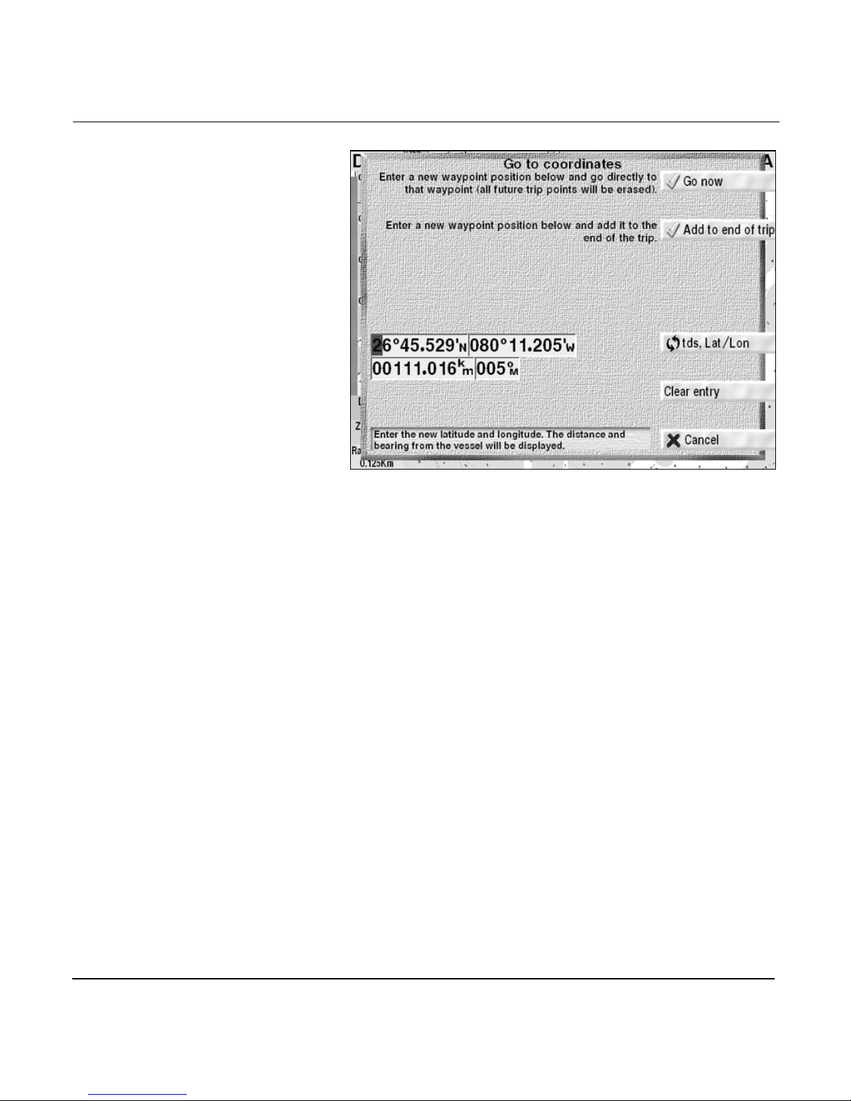
Chapter 4 - Understanding the Chart Screen
Go to coordinates dialog box
From this point, you can either go directly to the new
coordinates, or add the new coordinates to the end of your
trip.
Going to new coordinates now
Use this option to navigate directly from your present position
to the new waypoint:
1. From the CHART screen, press the GO TO key.
2. At the GO TO COORDINATES dialog box, use the
KEYPAD to enter the desired position coordinates or
distance and bearing.
3. Press the GO NOW key (or press the CANCEL key to
cancel).
On the
CHART
created named COORD to which you’re now going, and
appears as a track line to this new waypoint. The 961/962
automatically removes any future waypoints from your
trip, inserts your present vessel position and time as a
past point, and adds this new position as your existing
active waypoint.
screen, a waypoint is automatically
Page 4-6 961/962 Operations and Reference Manual, Rev. A
Page 99

Chapter 4 - Understanding the Chart Screen
Adding coordinates to the end of the trip
You can specify the next waypoint to go to before you reach
the active waypoint, called “queuing.” If you're unfamiliar with
the term queue, it means to put in line, as when several people
are waiting for service at a ticket window. By queuing
waypoints, you can navigate along a series of waypoints,
specifying the next waypoint at any time. Waypoint queuing
provides many of the advantages of following an entire route
automatically (see “Creating Routes” starting on page 8-1),
while providing the flexibility of easily handling last-minute
changes to your trip. You queue waypoints by adding new
coordinates to the end of your trip, which tells the 961/962
that you’d like to go to these coordinates—after you go to any
future trip waypoints already specified.
If you’ve already gone past the last waypoint, adding to the
end of the trip will restart navigation.
To queue a waypoint:
Restarting the
desired track
1. From the CHART screen, press the GO TO key.
2. At the GO TO COORDINATES dialog box, use the
KEYPAD to enter the desired position coordinates.
3. Press the ADD TO END OF TRIP key (or press the
CANCEL key to cancel).
A waypoint is created called
navigate at the end of your current trip, and the
screen is displayed showing the additional leg from the
previous end of the trip to the new waypoint.
When navigating from one waypoint to another, you may find
that you’ve wandered away from your intended course line.
Perhaps you avoided an obstacle or simply drifted slightly.
Whenever you go off-course for any reason, you can opt to go
directly to the waypoint by restarting the track line. Press the
RESTART HERE key to restart your course line from your
present position to the active waypoint, rather than maintain
your original course line (your trip isn’t changed).
To restart the track and go directly to the active waypoint:
COORD,
to which you’ll
CHART
961/962 Operations and Reference Manual, Rev. A Page 4-7
1. From the CHART screen, press the GO TO key.
Page 100

Chapter 4 - Understanding the Chart Screen
2. At the GO TO COORDINATES dialog box, press the
RESTART HERE key.
The your desired track is restarted to run from your
present position to the active waypoint, and the CHART
screen is displayed.
For an in-depth description of restarting the track, see
“Restarting the track” starting on page 10-19.
Selecting new
charts
At the CHART screen, you have four options for viewing other
charts:
• select a different chart appropriate for your position
• select from a list of charts at the vessel position or the
cursor position
• view a list of all charts in the database
• use a plotter grid instead of a chart
To quickly select a different chart, briefly press the NEW
CHART key. With each brief keypress, you’ll cycle through all
the available charts for your specific location—right on the
CHART screen. When you see the desired chart, stop pressing
the NEW CHART key. As you cycle through the available
charts, the 961/962 selects a chart of the same scale being
viewed until there’s a better scale to choose from. When there
aren’t any better charts to choose from, you’ll see the
MESSAGE FOR YOU, CAPTAIN! dialog box, informing you
that there is no better resolution chart available for your
position.
To view the charts stored in the database, press and hold the
NEW CHART key for about two seconds, and a list of the
installed charts containing the present position is displayed. If
the cursor wasn’t on the screen when you pressed NEW
CHART, a list of charts covering the present vessel position is
displayed; if the cursor was on the screen when you pressed
NEW CHART, a list of charts covering the cursor position is
displayed.
Page 4-8 961/962 Operations and Reference Manual, Rev. A
 Loading...