

Page 1
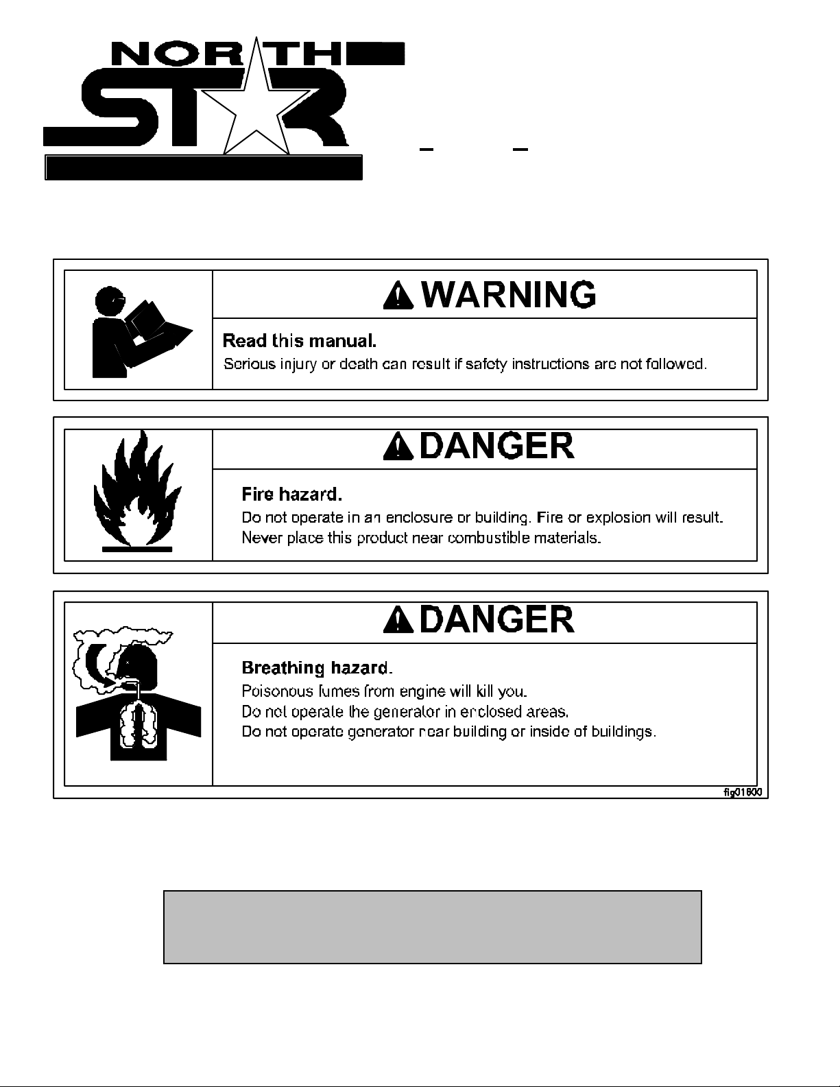
MO DEL 5000 PG, ITEM #165965
Portable Generator
Proven Performance
OWNER’S MANUAL
M165965A
Any Questions, Comments, or Problems?
Call Customer Service at 1-800-270-0810
Page 2
THANK YOU
Thank you for purchasing a NorthStar Portabl e Generator. Your machine is designed for long
life, dependability, and the top performance you demand. Please take time now to read through
this manual so you can better understand the machine’s operation, maintenance and safety
precautions. Everyone who operates this generator m ust read and understand this manual . The
time you take now will prolo ng you r ge ne rat or’s life and prepare you for its safe operation. Enjoy
the exceptional performance of your NorthStar Portable Generator.
IMPORTANT
Make certain the operator:
- Reads and understands the manuals pertai ning to this machine.
- Is instructed in safe and proper operation of this machine.
NOTICE
K-BAR Industries Incorporated reserves the right to make improvements in design and/or
changes in specifications at any time without incurring any obligation to install them on units
previousl y sold.
TABL E OF CONTE NTS
Thank you 1
Specifications 2
Machine com ponent ident ification 3
Gener ator f eature s 4
Introduction 4
A NSI safety definitions 4
Rules for safe operation 4-5
Installation 5
Load applic ation 5-7
Pre- star t up prepar ation 7-8
Starting 8
Stopping 8
Engine care 8
Gener ator car e 8
Troubleshooting 9
1
Page 3
SPECIFICATIONS
Item Nu mb er #165965
Maximum Outpu t 5000 Watts (W )
Continuous Output 4000 Watts (W )
Voltage 120 / 240 Volt (V)
Phase Single pha s e ( 4- wire)
Fr equenc y Regulatio n 56.5 - 63.3 Hert z (Hz)
Voltage Regulation 112-129V
Power Factor 1.0 p.f.
Engine 8 HP T ec um s eh ( HM80)
Engine Speed 3390 - 3798 RPM
Fuel Type Unle aded ga so line
Fuel Capacity 1 gallon (3.8 L)
Oil Capacity 1.63 US quar ts (1.5 L)
St ar ting Method Recoil
120 V Recept ac le 20 Amp (A) duplex (NEMA 5- 20R)
240 V Recept ac le 20 Amp (A) duplex (NEMA 6- 20R)
Circuit Breaker 17 Amp (A) thermal, push to reset
Gr ounding Post Receiv e s 12 Ga. wire or fork terminal
Dimensions
Length 26.00” ( 66 cm)
Width 19.00” ( 48 cm)
Height 17.50” ( 45 cm)
Dry W eight 106 lb. ( 45 k g)
Gr os s Weight 117 lb. ( 53 k g)
2
Page 4
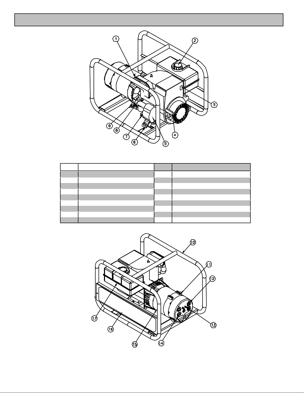
MACHI NE COMPO NENT IDENTIF ICAT ION
Figure 1 (Ref . 1-9) fig.01858
Ref. Description Ref. Description
1 Muffler 10 Protective Frame
2Gas Cap 11 Grounding Screw
3 Engine Stop Switch 12 120V 20A Duplex Rec
4 Recoil 13 Circ uit Brea ke rs
5 Air Cleaner 14 240V 20A Dupl ex Rec.
6 Vibration Isolation Mount 15 Genera to r Head
7 Oil Drain Plug 16 Warning Instructions
8 Choke Lever 17 Gas Tank
9 Dipstick
Figure 2 (10- 17) Fig01857
3
Page 5
GENERATOR FE ATURES
I NTRODUCTION
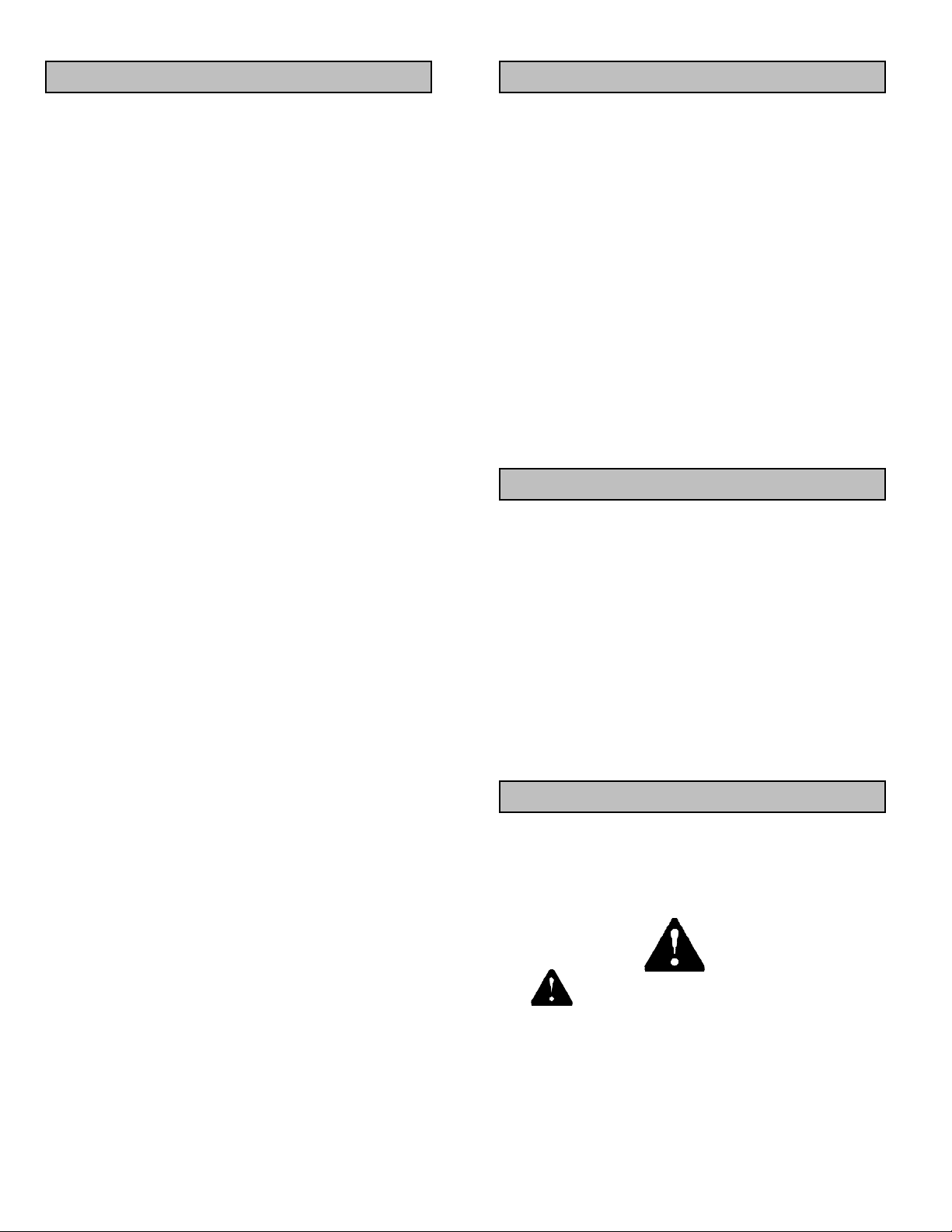
Reference 1 - Muffler. Allow 3’ clearance
around the hot exhaust gas.
Re ference 2 - Gas Cap .
Refe rence 3 - Engine S top Sw itch. The rocker
engine stop switch is l ocated on the engine. I means
ON. O means OFF.
Refer ence 4 - Recoil. Grasp firmly when starti ng
engine.
Reference 5 - Air Cleaner. Refer to your
Tecu mse h engine manual for air cleaner care.
Refe rence 6 - Vibr ation I solation M ounts. The
eng i ne an d g enerator ar e mou nt ed on r u bb er cy li nder s
that absorb most of the engine vibration. T his feature
eliminates the tendency of the m achi ne to “walk” whi ch
is com mo n in en gi ne pow er ed eq ui pmen t.
Reference 7 - Oil Drain Plug. Refer to your
Tecumseh engine manual for oil change
recommendations.
Reference 8 - Choke Lever. Used during cold
starts. Refer to the starting/stoppi ng instructions and
the T ecu mseh e ng in e ma nua l for us ag e.
Re ference 9 - Di p stick
Reference 10. Protective Frame. The frame
protects to engine and genera tor from dama ge.
Refe rence 11 - Gr ounding Sc rew. Ground the
generator via the grounding screw, to a copper pipe or
r od th at is driven i nto m ois t s oi l.
Reference 12 - 120V Receptacle. The generator
has a control panel with one duplex (two receptacles i n
a common housi ng) receptacle. The duplex is a 120
volt (V) 20 amp (A) straight blade receptacle, National
Electrical Manufacturer’s Associati on (NEMA) num ber
5-20R. Thi s receptacle accepts NEMA plug numbers
5-15P and 5-20P. Each receptacle on the duplex is
capa ble of dr aw ing 17A s im ul tan eously.
Reference 13 - Circuit Breakers. This portable
single phase generator has two, 17 amp (A) push to
reset circuit breakers to protect against electrical
overloads.
Reference 14 - 240V Receptacle. This device is
a 240V 20A NEMA 6-20R receptacle. This receptacle
accepts a NEMA plug number 6-20P.
ALWAYS use grounded male plugs. The neutral
line of the generator i s m echanical ly grounded to the
fram e. M atching NEMA male pl ugs must al ways be
used.
Re fer ence 15 - Ge ner ato r Head . The electrici ty
pr oduc i ng par t of t he ge ner ator .
Refe r ence 16 – Warni ng Ins tructions.
Reference 17 - Gas Tank. Always al low room
for gasoline expansion by not filling the gas tank
compl etely fu l l.
Before starting your generator, thoroughly study
the instructi ons and cautions in this manual to assure
you are fully acquainted with the operation of all
components of this generator. Proper preparation,
operation and maintenance will result in operator
s af ety , b est performanc e and lon g l ife of the g enerator.
For detailed engine operation and maintenance always
refer to the Tecumseh engine owner’s manual
furnished wi th the generator (Tecum seh refers to the
8 HP engine as a HM80).
NorthStar is constantly improving its products.
The specifications outlined herein are subject to
change without prior notice or obligation. The
purchaser and/or user shall assume liability of any
m od if i cati on an d /o r al te ra ti on s on th i s equi pm en t fr om
original design and m anufacture.
Before using, the user shall determine the
suitability of this product for its intended use and
assum es liability therein.
ANSI SAFETY DEFINITIONS
DANGER indicates an imminently hazardous
situati on whi c h, if not a v oide d, will result in dea th o r
serious injury. This signal word is to be limited to the
most extreme situations.
WARNING indicates a potentially hazardous
situation which, if not avoided, could result in a
dea th or seri ous i nj ur y.
CAUTION indicates a potentially hazardous
s ituatio n, w h ic h if not av o id ed , may r es ul t in min or or
moderate injury. It may also be used to alert against
uns af e pr actices.
RULES FOR SAFE OPERATIONS
Safety precautions are essential when operating
this generator. Respectful and cautious operation will
considerably lessen the possibilities of a personal
inj ury. Thi s m an ual will warn of specific pe rsonal injury
potential , and these will be de si gnated by the symbol:
WARNING This generator is equipped
with a gr ound in g p ost, located on th e co nt r o l pane l for
your protecti on. Always complete the grounding path
from the generator to a copper pipe/rod that is driven
into moi st earth, to prevent electrical shock.
ALWAYS use electrical cords that are in good
condition. Worn, bare, frayed or otherwise damaged
cords can cause electric shock.
4
Page 6
NEVER operate the generator, or handle any
electrical equipment while standing in water, while
barefoot, while hands are wet or while in the rain or
snow. Electric shock may result.
ALWAYS use a ground fault circuit interrupter
(GFCI) in damp or highly electrical conductive areas
and on construction job-sites to prevent el ectric shock.
ALWAYS remove the spark plug or spark plug
wire before working on the engine or generator, to
prevent accidental starting.
ALWAYS provide adequate ventilation. Do not
operate generator in any encl osed or narrow space.
Engi nes consume oxygen and give off deadl y carbon
monoxide poisonous gas. Improper ventilation will
cause damage to generator and possible injury to
people.
NEVER touch hot muffle r, hot exhaust mani fol d o r
engine cooling fins.
generator so that the exhaust fumes will not be
directed towards people.
The installation site must be free from water,
mo is tur e, or dus t. All e lect rica l c om pon ents s hould be
protected from excessive moisture or the insulation
system will deteriorate and result in grounding or
shorting out the generating system.
Foreign matters, such as dust, dirt, sand, lint, or
abrasive materials can cause damage to the generator
head and engine if allowed into its cooling system.
NEVER install your generator inside confined
areas. Inside i nstallati on can cause heal th hazards or
death.
DANGER Rem ember, exhaust fumes are
deadly carbon monoxide gas, and must be vented to
the outside where there are no people. Cooling air of
sufficient amounts must be allowed to flow in and
exhausted out to ensure proper cooling of the engine
and generator head.
ALWAYS re m o ve a ll oi l o r ga so li ne de posi t s an d
accumul ated dirt from generator and immediate area.
Keep generat or head and engine clean.
NEVER operate the generator under the following
conditions:
A. Excessive change in engine speed, slow or
fa st.
B. Over heat in g in lo ad c on nec ti ng dev ic es .
C. Sparking or arcs from generator.
D. Loss of electrical output.
E. Dam aged receptacles.
F. En gine misfi re.
G. Excessi ve vib ratio n.
H. Enclosed compartments, or confined areas.
I. Flame or smoke.
J. Rain, snow or wet conditions.
K. Operator non-attendance.
WARNING Check fuel system on a
regular basis. Look for signs of leaks, deterioration,
chafed or spongy fuel hose, loose or m i ssing fuel hose
clamps, damaged fuel tank or a defective fuel shut-off
valve. Correct any defects before operation.
WARNING Keep fire extingui sher cl ose
by your generator and be familiar on how to use it.
Consult your local fire department for correct
extingui sher type.
INSTALLATION
OUTDOORS: Choose locations where the
ge nera tor will not b e exp osed to rain , sno w or dire ct
sunlight. Position the generator on secure, level
ground so it wi ll not tip or sl ide down a hill. Place the
LOAD APPLICATION
It is i mportant to determine the total el ectrical load
bef or e it is conn ec t ed to t he ge ner ator . The tw o ma jor
factors in determining the life of a generator head are
heat build-up, caused by overloading the generator
and corrosive contaminants that can attack the wi ring
insulation. If the generator is overloaded, the wires
become excessively hot and cause the insulation to
break down, reducing its ability to resist corrosive
contaminants. Over time the effectiveness of the
insulation is elim inated and a dead short can resul t.
Always compare the generator nameplate data
with that of the equipment to be used to ensure that
watts, volts, amperage, and frequency requirements
are suitable for operating equipment. The wattage
listed on the equipment namepl ate i s i ts rated output.
However, some equi pment may require three to ten
tim es m ore wattage than i ts rating on the nameplate,
as the wattage is influenced by the equipment
efficiency, power factor and starti ng system. NOT E: If
wattage is not given on equipment nameplate,
approximate wattage may be determined by
multiplying nameplate voltage by nameplate
amperage.
VOLTS X AMPS = WATTS
Example: 120V X 5A = 600W
When connecting a resistive load such as
incandescent lights, heaters or common electri c power
tools, a capacity of up to the generator full rated
wattage output can be used.
When connecting a resistive-inductive load such
as a fluorescent or mercury light, transformers or
inductive coils, a capacity of up to 0.6 times the
generator’s full rated output can be used.
Always allow the generator to reach operating
speed before a load is appli ed.
5
Page 7
STARTI NG EL ECTRIC MO TORS
EXTENSION CORDS
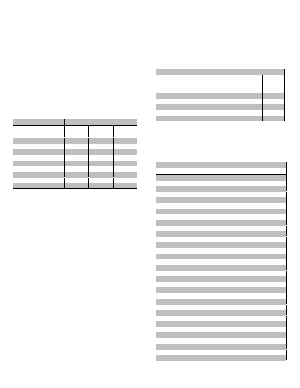
El ect ri c mo to rs req ui re m uch mo re cu rre nt (a mps)
to sta rt tha n to run. Some motors, particularly low cost
spli t-phase m otors, are very hard to start and require 5
to 7 times more current to start than to run. Capacitor
motors are easier to start and usually require 2 to 4
tim es as much current to start than to run. Repul si on
Induction motors are the easi est to start and require
1.5 to 2.5 ti mes as much to start than to run.
Most fractional motors take about the same
amount of current to run them whether they are of
Repulsion-Induction (RI), Capacitor (Cap), or Split-
Phase (SP) type. The following chart shows the
approximate current required to start and run vari ous
types and sizes of 120 volt 60 cycle electric motors
under various conditions.
120 V, 60 Hz Mo t o rs
Hp motor Running
Watts
1/6 525 7-11 9-18 16-22
1/4 700 9-15 12-23 22-32
1/3 875 11-18 14-29 26-35
1/2 1175 15-25 20-40 NA
1 1925 24-40 32-64 NA
1 1/2 2400 30-50 40-80 NA
2 2900 36-60 48-96 NA
3 4075 51-85 68-136 NA
5 6750 84-140 112-224 NA
The fi gures given above are for an average load
such as a blower or fan. If the electric motor is
connected to a hard starting load such as an air
co mpresso r, it will require more starting c urrent. If i t is
connected to a light load or no l oad such as a power
saw, it will require less starting current. The exact
req uirem ent will al so vary with th e bra nd o r d esign of
the mo tor .
Generators respond to severe overloading
differentl y than the power line. When overloaded, the
engine i s not able to supply enough power to bring the
electric motor up to operati ng speed. The generator
responds to the high initial starting current, but the
engine speed drops sharply. The overload may stall
the engine. If allowed to operate at very low speeds,
the electric motor starting winding will burn out in a
short time. The generator winding might also be
damaged.
Running the generator under these conditions may
r es ult in da ma ge to t he ge ner a t or s tat or as wel l as th e
motor windi ngs. Because the heavy surge of current
is required for only an insta nt , the gen erator will not be
dam aged if it can bring the m otor up to speed in a few
seconds. If difficulties in starting a motor are
experienced, turn off all other electrical loads and if
possibl e reduce the load on the electric motor.
RI type Cap type SP type
Starting Am ps
When electri c power is to be provi ded to various
loads at some di stance from the generator, extensi on
cords can be used. T hese cords should be sized to
allow for distance in length and amperage so that the
voltage drop between the set and point of use is held
t o a minimum.
Current/ Power Maxi m um Extension Cord Le ngth
Amps
at
240V
10 2400 250’ 150’ 100’ 75’
20 4800 125’ 75’ 50’ 25’
30 7200 60’ 35’ 25’ 10’
40 9600 30’ 15’ 10’ *
50 12000 15’ * * *
low voltage caused by using an extension cord with a
smal l wire size.
generator.
Device Running Wa tts
Air Conditi oner (12,000 Btu) 1700 (a)
Battery Charger (20 Amp) 500
Belt Sand er (3”) 1000
Chain Saw 1200
Circ ular Saw (6-1/2”) 900
Coffee Maker 1000
Co mp resso r (1 H P) 2000 (a)
Co mp resso r (3/4 HP) 1800 (a)
Co mp resso r (1/2 HP) 1400 (a)
Curling Iron 700
Dishwas her 1200
Edg e Tri m mer 500
Electric Nail Gun 1200
Electric Range (one el ement) 1500
Elec tr ic Sk ill et 1250
Furnace Fan (1/3 HP) 1200 (a)
Freezer 800 (b)
Hair Drye r 1200
Hand Drill (1”) 1100
Hand Drill (1/2”) 875
Hand Drill (3/8”) 500
Hand Drill (1/4”) 250
Hedge Tri mm er 450
Home Computer 150
Impact Wrench 500
Jet Pump 800 (a)
Lawn Mower 1200
Light Bulb 100
Microw ave O ve n 700
Milk Cooler 1100 (a)
Oil Burner on Furnace 300
Oil Fired Space Htr (140,000 Btu) 400
Oil Fired Space Htr (85,000 Btu) 225
Load
(wa tts)
*Not recommended
CAUTION: Equipment damage can resul t from the
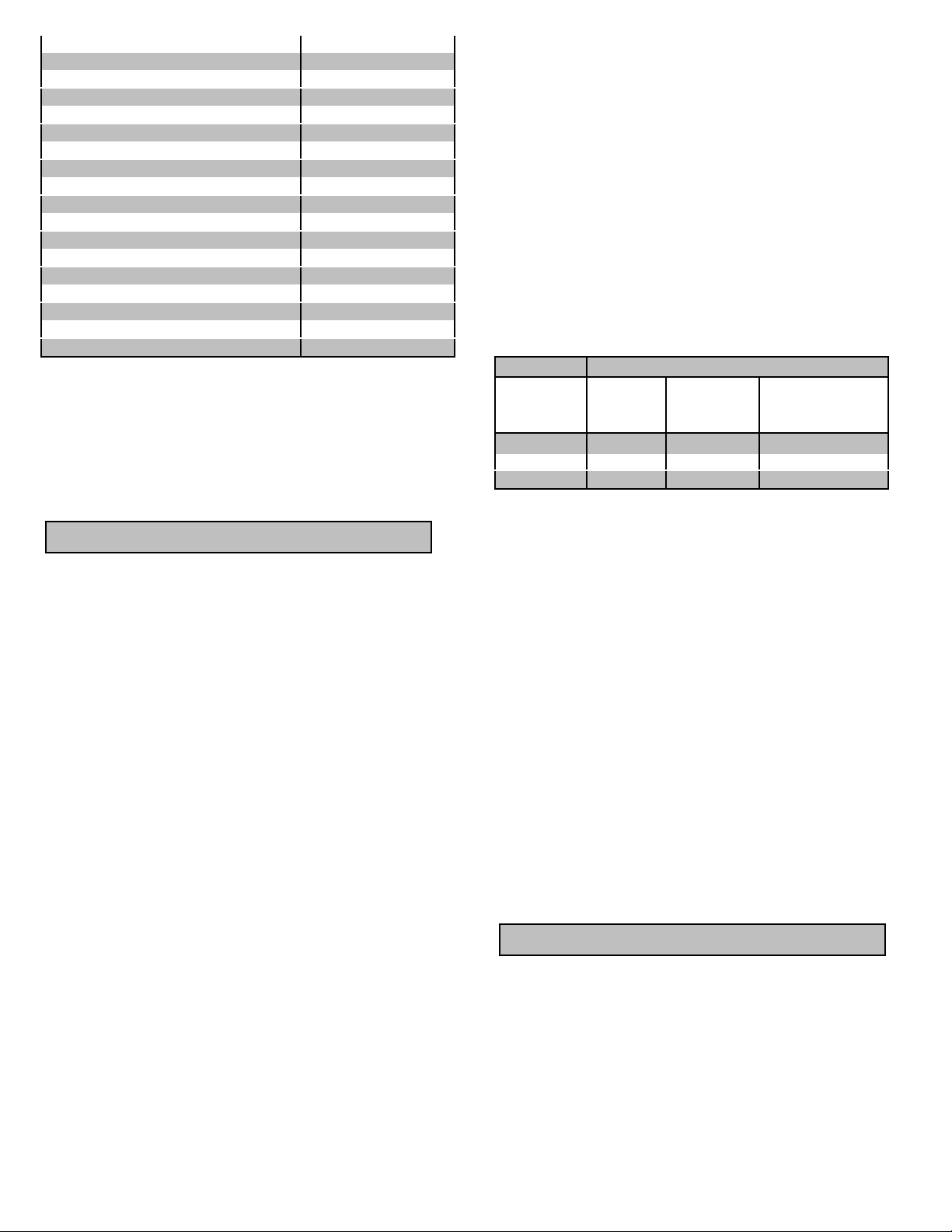
Use this chart to estimate the total load on your
For Determining Generator Load Requirements
#10
Ga.
Cord
#12
Ga.
Cord
#14
Ga.
Cord
#16
Ga.
Cord
6
Page 8
Oil Fired Space Htr (30,000 Btu) 150
Oven 4500
Pain t S prayer, Airless (1/3 HP) 6 00 (a)
Pai nt Sprayer, Airless (handheld) 150
Radio 200
Refrigerator 600 (b)
Slow Cooker 200
Submersible Pum p (1- 1/2 H P) 2800 (a)
Submersible Pump (1 HP) 2000 (a)
Submersible Pum p (1/2 H P) 1500 (a)
Sump Pump 600 (a )
Table Saw (1 0” ) 2000 (a)
Television 500
Toaster 1000
Vacuum Cleaner 250
VCR 70
Water Heater 3000
W eed Tri m mer 500
(a ) Hard -sta rt in g mo to rs re q uire 3 to 5 t im es the
rated running watts.
(b) These loads may require up to 15 minutes to
restart due to its normal build up of compressor head
pressure.
NOT E: For extremel y hard to start loads such as
air conditioners and air compressors, consult the
equipment deal er to determine the maximum wattage.
PRE-START PREPAR ATIO NS
Your generator has been thoroughly tested prior to
shipment from the factory. A factory test report has
been included with this manual. However, damage
can occur during shipping, so be sure to check for
dam aged parts or loose or missing nuts and bolts. If
the aforementioned problems occur, call Customer
Service at 1-800-270-0810.
GRO UNDING - All units must be grounded. Dr ive
a 3/4” or 1” copper pipe or rod into the ground close to
the generator. The pipe/rod must penetrate moist
earth. Connect an approved ground clamp to the pi pe.
Run a no. 12 Ga. wire from the clamp to the generator
grounding post located on the control panel . Do not
connect to a water pi pe or a ground used by a radio
system.
CAUTION: The engine has been shipped without
oil. Fill the crankcase with oil before trying to start.
Low oil shut down prevents your generator from
startin g without sufficient oil.
damage to equipment plugged into the unit and
possibl e injury to the indi vidual.
All engines have a tendency to slow down when a
load is applied. When the electrical load is connected
to the generator, the engine is more heavily loaded,
and as a result the speed drops sli ghtly. This slight
decrease in speed, together with the voltage drop
within the generator itself, results in a slightly lower
voltage when the generator is loaded to its full capacity
than when it is running with no load. The slight
variation has no appreciable effect in the operation of
motors, lights and most appliances. Electronic
equipment and clocks will be affected if correct RPM is
not maintained. See Load vs. Output chart.
Load Output
Percent of
Genera to r
Output
0 % 3780 63.0 129V
50 % 3600 60.0 120V
100 % 3510 58.5 112V
Output voltage should be checked periodically to
ensure conti nued proper operation of the generating
plant and appliances. It can be checked with a
portable meter. Frequency can be checked by using
an electric clock with a sweep second hand. Timed
against a wrist watch or a stop watch the cl ock should
be correct within +/- 2 seconds per minute. All speed
setting adjustments should be done by a qualified
technician.
Speed
(RPM)
Frequency
(Hz)
Genera to r
Vo lta ge at 120V
Receptacle
BEFORE STARTING
1. Make sure the generator is posi tioned on firm
level surface.
2. Check the crankcase for oil and maintai n at a
pr oper lev e l.
3. Check fuel level and fill tank with fresh unleaded
gas ol in e if neces sar y. Allow for gasolin e expansion by
never filling fuel tank completely to the top. Always
wipe up and remove any spilled gasoline.
4. Make sure that the exhaust fumes are directed
away from people.
STARTING
OPERAT ING SPEE D
The generator must be run at the correct speed in
order to produce the proper electrical voltage and
frequency. The speed of the engine was carefully
adj usted at the factory so that the generator produces
the proper voltage and frequency.
The output vol tage should be checked to ensure
the generator is worki ng properly before connecting a
load to the generator. Failure to do so could result i n
1. Disconnect all loads to generator.
2 . M ov e en gi ne on- of f le v e r l o cat ed on e ngi ne t o
the I pos ition .
3. For cold engine, move choke lever to full choke
position. For a warm engine, move choke lever to to
hal f choke or run position.
4. Grasp recoil handle and pull.
5. When engine starts, move choke lever to run
position.
6. Loads may now be connected to generator.
7
Page 9
STOPPING
1. Disconnect all loads to generator.
2. Move engine on-off switch to the O position.
ENGINE CAR E
Refer to your Tecumseh Owner’s Manual for
proper care and maintenance.
CAUTION NEVER change oil on a hot
engine, the hot oil could cause severe burns.
GENERATOR CAR E
The generator head is a two pole, 3600 RPM, 60
Hz, brushless, revolving field and synchronous type
with one seal ed radial roller bearing. The rotor of the
generator head is directly connected to the engine
crank shaft and the stator is rigidly coupled to the
engine casting via the generator head casting.
Exercising The Generator - The generator
shoul d be ope ra ted eve ry four w ee ks . Warm the
uni t up by starting the engine and letting it run for 10 to
15 minutes. This will dry out any moi sture that has
accum ul ate d in the wi ndings. If left, this moisture ca n
cause corrosion in the wi nding. Frequent operation of
the engine generator will also ensure that the set i s
operating properly should it be needed in an
emergency.
Ge ne ra tor Ma inte na nce - The generator head i s
brushless and maintenance free. Any m ajor generator
service including the installation or replacement of
parts should be performed only by a qualified electrical
service technician. USE ONLY FACTORY
APPROVED REPAIR PART S. Ob tain all factory p arts
from Customer Service at 1-800-270-0810.
A. Bearing - The bearing used in these generators
is a heavy duty sealed ball beari ng. They requi re no
maintenance or lubrication.
B. Receptacles - Quality receptacles have been
utilized. If a receptacle should become cracked or
otherwise damaged, replace it. Using cracked or
damaged receptacles can be both dangerous to the
operator and destructive to the equipment.
Stand-by Operation
If your generator is to be used as a standby
electric power source in case of utility failure, it must
be installed by a registered and licensed electrician
and in compliance with all applicable state and local
electrical codes. Also, local Fire Departments m ust be
consulted concerning proper and safe handling
procedures for gasoline. NEVER connect any
generator to any exi sti ng electrical system without an
isolating, UL approved transfer switch, installed by a
licensed electrician.
8
Page 10
TROUBLESHOOTING
Proble m Possible Causes Possible Remedies
Engi ne will not start. a) Low oil level.
b) Fouled spark pl ug.
c) Out of fuel.
d) Stop switch in OFF position.
Voltage too low. a) Engine speed too slow.
b) Ge nerator is overl o aded .
Circuit b reake r trips. a ) Defective load conne cted to gene rator.
b) Defective receptacl e.
c) Generator ov erloaded.
Voltage too high. a) Engine speed too high. a) Br ing generator to a qualified
Gen er ator ov er h eatin g. a) Gen er ator is overloade d.
b) In sufficient ventilatio n.
No output voltage. a) Defecti ve load connected to generator.
b) Broken or loose wire.
c) Defective receptacl e.
d) Defective stator.
e) Defective rotor.
f) Defective capacito r.
Engine lacks power. a) Generator is overloaded.
b ) Dirty air filter.
Engi ne shuts down
dur ing oper at io n.
a) Ou t of fuel.
b) Low oil level.
a) Fill crankcase to proper oil level.
b) Clean or replace spark pl ug.
c) Fi ll fuel tank.
d) Place switch in ON positi on.
a) B r ing generat or t o a qualified
technician for adjustment.
b) Reduce the l oad. (See Load
Application section of this manual .)
a) Disconnect load.
b) Replace receptacl e.
c) Reduce the load. (See Load
Application section of this manual .)
technician for adjustment.
a) Reduce the l oad. (See Load
Application section of this manual .)
b) Make sure there is at l east 3 feet of
clear ance on all sides of generator.
a) Disconnect load.
b) B r ing generat or t o a qualified
tec hnician for repair.
c) Replace receptacle.
d) B r ing generat or t o a qualified
tec hnician for repair.
e) B r ing generat or t o a qualified
tec hnician for repair.
f ) B r ing generat or t o a qualified
tec hnician for repair.
a) Reduce the l oad. (See Load
Application section of this manual .)
b) Clean or replace air filter.
a) Fill fuel tan k.
b) Fill crankcase to proper oil level.
9
 Loading...