

Page 1

490 ECHO SOUNDER
INSTALLATION MANUAL
Rev B2
Part Number G M491
Northstar Technologies
30 Sudbury Road
Acton, Massachusetts 01720
www.NorthstarNav.com
Service: 978/897-0770
Sales: 978/897-6600
Page 2

Page 3

Limited warranty policy
Northstar Technologies, Inc., warrants the Northstar 490 to be free from defects in materials and
workmanship for a period of two (2) years. This warranty applies to the original purchaser and to any
subsequent owner during the warranty period, which begins on the date of shipment of the unit,
F.O.B. Acton, Massachusetts, to an authorized Northstar dealer.
Systems may not be returned to Northstar without a Returned Materials Authorization (RMA) number. Call the Northstar dealer or Northstar for instructions.
During the unit’s warranty period, Northstar will repair or replace, at its option, any part of the unit it
finds to be defective due to faulty material(s) or workmanship. All such repairs and/or replacements
will be promptly performed by Northstar free-of-charge to the owner, excluding freight costs
incurred in shipping to the factory. Return shipments from Northstar to points within the United
States are made via ground transportation, freight prepaid. Special shipping charges (overnight,
two-day, and so on) are the responsibility of the owner.
To be covered by this warranty, the Northstar equipment must have been in normal use. This warranty does not apply to units with defects caused by improper installation, physical damage, abuse,
tampering, lightning or other abnormal electrical discharge, or to units with defaced or altered serial
numbers, or to units repaired by unauthorized persons or repaired in a manner that violates Northstar’s recommended service procedures.
All repairs and/or replacements made under this warranty must be performed at Northstar’s facilities
in Acton, Massachusetts. Performance of warranty work elsewhere will not be authorized, and Northstar will not pay for any charges for such work. Northstar will not be responsible for payment of any
charges imposed by a Northstar dealer or other party for services requested by and/or performed for
a unit’s owner in connection with this warranty. Such services might include removal of the unit
from a vessel, inspection, packaging, handling, reinstallation, and the like.
Northstar Technologies assumes no responsibility for any consequential losses of any nature with
respect to any of its products or services sold, rendered, or delivered. The foregoing is the only warranty expressed or implied. No other warranty exists.
Page 4

Page 5

490 INSTALLATION MANUAL, Revision B2 Page i
Table of Contents
SECTION ONE Introduction . . . . . . . . . . . . . . . . . . . . . . . . . . . . . . . . . . . . . . . . . . . . . . . . . . . . . . . . . . . . . . . . . . . . . . . . .1
Welcome to the Northstar 490 . . . . . . . . . . . . . . . . . . . . . . . . . . . . . . . . . . . . . . . . . . . . . . . . . . . . . . . . .1
Who should read this manual . . . . . . . . . . . . . . . . . . . . . . . . . . . . . . . . . . . . . . . . . . . . . . . . . . . . . . . . . . 2
Scope of this manual . . . . . . . . . . . . . . . . . . . . . . . . . . . . . . . . . . . . . . . . . . . . . . . . . . . . . . . . . . . . . . . . . .2
Installation considerations . . . . . . . . . . . . . . . . . . . . . . . . . . . . . . . . . . . . . . . . . . . . . . . . . . . . . . . . . . . . . 2
SECTION TWO Installing the transducer. . . . . . . . . . . . . . . . . . . . . . . . . . . . . . . . . . . . . . . . . . . . . . . . . . . . . . . . . . . . .5
Safety considerations. . . . . . . . . . . . . . . . . . . . . . . . . . . . . . . . . . . . . . . . . . . . . . . . . . . . . . . . . . . . . . . . . .5
Selecting a transducer . . . . . . . . . . . . . . . . . . . . . . . . . . . . . . . . . . . . . . . . . . . . . . . . . . . . . . . . . . . . . . . . .6
Installation considerations . . . . . . . . . . . . . . . . . . . . . . . . . . . . . . . . . . . . . . . . . . . . . . . . . . . . . . . . . . . . . 7
Choosing a mounting location . . . . . . . . . . . . . . . . . . . . . . . . . . . . . . . . . . . . . . . . . . . . . . . . . . . . . . . . .7
Installing a transducer . . . . . . . . . . . . . . . . . . . . . . . . . . . . . . . . . . . . . . . . . . . . . . . . . . . . . . . . . . . . . . .10
Maintaining a transducer . . . . . . . . . . . . . . . . . . . . . . . . . . . . . . . . . . . . . . . . . . . . . . . . . . . . . . . . . . . . .11
SECTION THREE Installing the 490 . . . . . . . . . . . . . . . . . . . . . . . . . . . . . . . . . . . . . . . . . . . . . . . . . . . . . . . . . . . . . . . . 13
Safety considerations. . . . . . . . . . . . . . . . . . . . . . . . . . . . . . . . . . . . . . . . . . . . . . . . . . . . . . . . . . . . . . . . .13
System components. . . . . . . . . . . . . . . . . . . . . . . . . . . . . . . . . . . . . . . . . . . . . . . . . . . . . . . . . . . . . . . . . .14
Choosing a mounting location . . . . . . . . . . . . . . . . . . . . . . . . . . . . . . . . . . . . . . . . . . . . . . . . . . . . . . . .15
Mounting the 490 . . . . . . . . . . . . . . . . . . . . . . . . . . . . . . . . . . . . . . . . . . . . . . . . . . . . . . . . . . . . . . . . . . .16
Wiring the 490 . . . . . . . . . . . . . . . . . . . . . . . . . . . . . . . . . . . . . . . . . . . . . . . . . . . . . . . . . . . . . . . . . . . . . .17
Powering up, setting up, and powering down the 490 . . . . . . . . . . . . . . . . . . . . . . . . . . . . . . . . . . . .21
Installation-test checklist . . . . . . . . . . . . . . . . . . . . . . . . . . . . . . . . . . . . . . . . . . . . . . . . . . . . . . . . . . . . .22
SECTION FOUR Troubleshooting and servicing the 490 . . . . . . . . . . . . . . . . . . . . . . . . . . . . . . . . . . . . . . . . . . . 23
Troubleshooting common 490 installation problems . . . . . . . . . . . . . . . . . . . . . . . . . . . . . . . . . . . . .23
Getting technical support . . . . . . . . . . . . . . . . . . . . . . . . . . . . . . . . . . . . . . . . . . . . . . . . . . . . . . . . . . . . .26
Ordering replacement parts . . . . . . . . . . . . . . . . . . . . . . . . . . . . . . . . . . . . . . . . . . . . . . . . . . . . . . . . . . .27
Servicing the 490 . . . . . . . . . . . . . . . . . . . . . . . . . . . . . . . . . . . . . . . . . . . . . . . . . . . . . . . . . . . . . . . . . . . .27
Returning a 490 for service . . . . . . . . . . . . . . . . . . . . . . . . . . . . . . . . . . . . . . . . . . . . . . . . . . . . . . . . . . .28
APPENDIX A Technical specifications . . . . . . . . . . . . . . . . . . . . . . . . . . . . . . . . . . . . . . . . . . . . . . . . . . . . . . . . . . . . . 29
Glossary . . . . . . . . . . . . . . . . . . . . . . . . . . . . . . . . . . . . . . . . . . . . . . . . . . . . . . . . . . . . . . . . . . . . . . . . . . . . . . . . . . . . . . . . . . 31
Page 6

Page ii 490 INSTALLATION MANUAL, Revision B2
Page 7

490 INSTALLATION MANUAL, Revision B2 Page 1
SECTION ONE
Introduction
Welcome to the
Northstar 490
An echo sounder is a device that provides information about
the water directly beneath a vessel. The echo sounder system
consists of:
• the Northstar 490 echo sounder sensor
• a Northstar navigation system such as the 961/962 or 957/
958
• a transducer
The 490 is available in two models:
• the model 490-D is a 1000-watt dual channel echo
sounder designed to be used with a transducer having
dual ceramic elements, one each for 50 and 200 kHz
• the model 490-S is a 600-watt single channel echo sounder
designed to be used with a transducer having a single
ceramic element capable of 50 and 200 kHz
In this manual, the term “490” refers to both models. For more
information about the 490-D and 490-S, see ”System
components” on page 14.
Page 8

SECTION ONE Introduction
Page 2 490 INSTALLATION MANUAL, Revision B2
Who should read
this manual
This manual is for marine technicians who are installing the
Northstar 490 and connecting it with the Northstar 961/962
processor or Northstar 957/958, and a transducer.
Scope of this
manual
In this manual, you’ll find information about the following:
• mounting and wiring the 490
• connecting the 490 to the Northstar 961/962 or 957/958
• installing a transducer (an overview is provided, but for
such details as wiring, see the documentation provided by
the transducer’s manufacturer)
• connecting the 490 to a transducer (see also the
Transducer Connector Instructions—GM492)
• troubleshooting and testing the system
• technical specifications for the 490
For information about obtaining technical support and
returning the 490 for factory service, see “SECTION FOUR
Troubleshooting and servicing the 490” beginning on page 23.
For details about operating the 490 using the 961/962 or 957/
958, see the Northstar 490 Echo Sounder Operations Manual
(GM490).
Installation
considerations
1. Check the shipping carton for any damage, and
immediately report any damage to the carrier. Save all
packing material in case you have to return the 490 to
the factory for repair or evaluation.
2. Unpack the carton, and check its contents. You should
have received:
CAUTION!
The following list of installation considerations isn’t
a substitute for all the details in Section Three. To
ensure that you meet all critical installation
parameters, be sure to read that entire section and
follow all of its recommendations.
Page 9

SECTION ONE Introduction
490 INSTALLATION MANUAL, Revision B2 Page 3
• the Northstar 490 Echo Sounder (-D or -S model)
• 10-foot (3-meter) data cable to connect the 490 to the
961/962 or 957/958
• 10-foot (3-meter) power cable for the 490
• 490 parts kit (containing transducer cable end
connector, backshell, heatshrink tubing, and the
Transducer Connector Instructions—GM492)
• Northstar 490 Echo Sounder Installation Manual
(GM491)
• Northstar 490 Echo Sounder Operations Manual
(GM490)
• warranty card
3. Fill out the warranty card and mail it to Northstar.
4. Review all of the installation requirements as outlined in
Sections Two and Three.
5. Install the transducer, then terminate the cable (see
”Connecting the 490 to a transducer” starting on page
20).
6. Mount the 490. For instructions, see ”Mounting the 490”
on page 16.
7. Connect the 490 to ship’s power and to the 961/962
processor or the 957/958. Connection information begins
on page 17.
With the vessel in the water, turn on the system and verify
proper operation.
Page 10

SECTION ONE Introduction
Page 4 490 INSTALLATION MANUAL, Revision B2
Page 11

490 INSTALLATION MANUAL, Revision B2 Page 5
SECTION TWO
Installing the
transducer
Safety
considerations
WARNING!
Be sure to turn the power off before starting the
installation. Further, it is highly recommended that
you keep power off while you’re performing the
installation. If power is left on or turned on during
the installation, fire, electrical shock, or other
serious injury may occur.
Be sure to ground the equipment to prevent
electrical shock and mutual interference.
Be sure the transducer outputs are tied together
before handling to avoid electrical charge build-up.
WARNING!
Be sure to use a 3-amp fuse. Using the incorrect
fuse can result in fire or damage to the 490.
Page 12

SECTION TWO Installing the transducer
Page 6 490 INSTALLATION MANUAL, Revision B2
Selecting a
transducer
Northstar recommends using an Airmar transducer with the
Northstar’s 490 echo sounder.
CAUTION!
Mounting the transducer requires drilling holes
through the hull; make sure the installation does not
cause the vessel to leak. A thru-hull installation
should be performed by a professional installer. Do
not attempt this unless you are fully qualified.
Do not perform a thru-hull installation of the
transducer when the vessel is actually in the water.
Immediately
after installing the transducer, be sure
to check for leaks, and don’t leave the vessel in the
water for more than three hours before checking it
again.
Northstar assumes no responsibility for improper
installation of a transducer.
NOTE:
Be sure that the transducer doesn’t interfere with
any of the on-board systems. Check all other
systems to ensure that their performance doesn’t
degrade when the transducer is connected.
Table 1: Northstar-recommended transducers
Manufacturer Housing Power Frequency
Airmar B250
(P/N 41-088-1-01)
1 kW 50/200 kHz
Airmar B744V/B44V (with
3-wire speed)
600 W 50/200 kHz
Page 13
SECTION TWO Installing the transducer
490 INSTALLATION MANUAL, Revision B2 Page 7
To purchase a single transducer, contact GEM Electronics at:
GEM Electronics Company
110 South Acline Avenue
Lake City, South Carolina 29560
Phone 843/394-3565
Fax 843/394-3736
If you are a dealer and want to purchase multiple transducers,
you can reach Airmar Technology Corporation at:
Airmar Technology Corporation (www.airmar.com)
35 Meadowbrook Drive
Milford, New Hampshire 03055-4613
Phone 603/673-9570
Fax 603/673-4624
For a list of transducers that are compatible with the Northstar
490, visit Northstar’s website at:
www.NorthstarNav.com
Installation
considerations
The following basic setup information isn’t a substitute for the
installation instructions provided by the transducer’s
manufacturer. To ensure that you meet all critical installation
parameters, be sure to read and follow all of the requirements
in their instructions. Northstar assumes no responsibility for
improper installation.
Choosing a
mounting
location
CAUTION!
Do not mount the transducer:
• behind strakes, fittings, or hull irregularities
(mounting in those locations may increase
turbulence, aeration, and cavitation) or near the
keel
• near openings for water intake or discharge
• where it might be loosened by the vessel’s
vibration
• less than four feet away from the Northstar 961/
962 processor to minimize interference
Page 14

SECTION TWO Installing the transducer
Page 8 490 INSTALLATION MANUAL, Revision B2
The two most common problems with echo sounder
installations stem from noise and cavitation. Either of these
situations can produce poor performance.
Noise occurs when the transducer cable is routed too closely to
noise-producing electronics, such as alternators, AC generators,
radars, etc. To avoid problems with noise, route the transducer
cable by itself (not in a bundle) and away from other wires or
cables and the engine.
Cavitation is similar to hydroplaning. In some cases, air bubbles
will come between the transducer and the water. When this
happens, the transducer can’t get its energy into the water
properly, and won’t be able to detect any echoes. To avoid
cavitation, choose a mounting location with good water flow all
around it at all speeds.
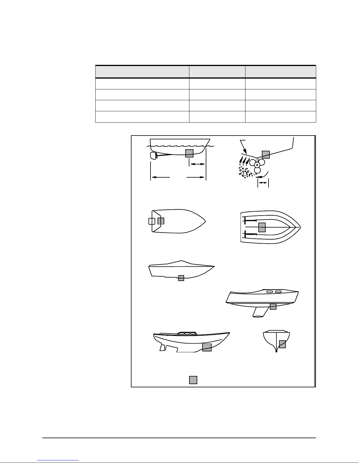
Before any drilling or cutting takes place, carefully choose a
mounting location for the transducer that meets the following
criteria (also see Figure 1 on page 9), depending on the type of
vessel:
• the transducer and its cable are as far as possible from
other electrical cables
• leaves room above the transducer for the transducer’s
stem, housing, and cable
• the path for running the transducer’s cable is reasonably
direct—keep in mind that the transducer cable is 33 feet
long (10 meters). To prevent damage, coil any excess cable
and secure it
• water turbulence and noise are minimal, decreasing the
amount of bubbles passing over the transducer face
• the transducer isn’t behind hull irregularities or near
eroding paint; both indicate areas subject to turbulence
• the transducer is as far as possible from the engine or
propellers, and inboard of the lifting strakes
• the transducer always remains submerged and
perpendicular to the waterline
• the transducer is easily accessible from inside the vessel
for adjustments and maintenance
• the transducer’s ultrasonic beams aren’t obstructed by the
keel, propeller shafts, or any other part of the vessel
• the transducer is parallel with the water surface
• the hull thickness falls within the limits in Table 2 below
(all dimensions are perpendicular to the waterline):
Choose the mounting
location to obtain the best
possible performance from
the transducer and the 490.
Take into account the
vessel’s maximum speed
when selecting a mounting
location, as turbulence can
affect echo sounding
capabilities.
Page 15
SECTION TWO Installing the transducer
490 INSTALLATION MANUAL, Revision B2 Page 9
Figure 1: Recommended installation locations for a transducer
Table 2: Hull thickness limits
Model Minimum Maximum
AirMar B44V/B744V with fairing 6 mm (1/4 inch) 19 mm (3/4 inch)
AirMar B44V/B744V without fairing 6 mm (1/4 inch) 65 mm (2 1/2 inches)
AirMar B250 with fairing —— 45 mm (1 3/4 inches)
AirMar B250 without fairing 19 mm (3/4 inch) 114 mm (4 1/2 inches)
inboard
pressure waves
1/3 aft
full keel sailboat
displacement hull
(6-12")
fin keel sailboat
150-300mm
LWL
Best location for the transducer
(Load Waterline Length)
step-hull
outboard and I/O
planning hulls
Page 16
SECTION TWO Installing the transducer
Page 10 490 INSTALLATION MANUAL, Revision B2
Installing a
transducer
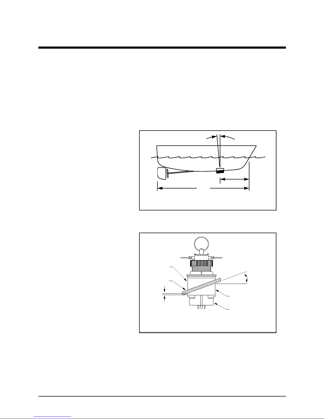
A flat-bottom hull provides the best environment for mounting
the transducer: It provides a horizontal surface and a constant
water flow over the transducer, with little turbulence (see
Figure 2 for the recommended transducer incline angle). If the
vessel has a deadrise angle greater than 5 degrees, mount the
transducer on a fairing block to create a horizontal surface and
keep the transducer perpendicular to the waterline (see
Figure 3). You must order the fairing block, if needed, from the
transducer’s manufacturer.
Figure 2: Recommended transducer incline angle
Figure 3: Typical finished thru-hull installation with a fairing block (Airmar B44V)
3° incline
1/3 aft
(Load Waterline Length)
LWL
angle
6–12mm (1/4–1/2")
backing
hull
fairing
multisensor
deadrise
fairing thickness
angle
slope of hull
parallel to
waterline
block
Deadrise angle and fairing thickness (B44V shown)
at narrowest point
Page 17
SECTION TWO Installing the transducer
490 INSTALLATION MANUAL, Revision B2 Page 11
Maintaining a
transducer
Do not expose the transducer’s face or plastic housing to
gasoline or strong solvents, such as acetone. These solvents can
penetrate and degrade many plastics and reduce their strength.
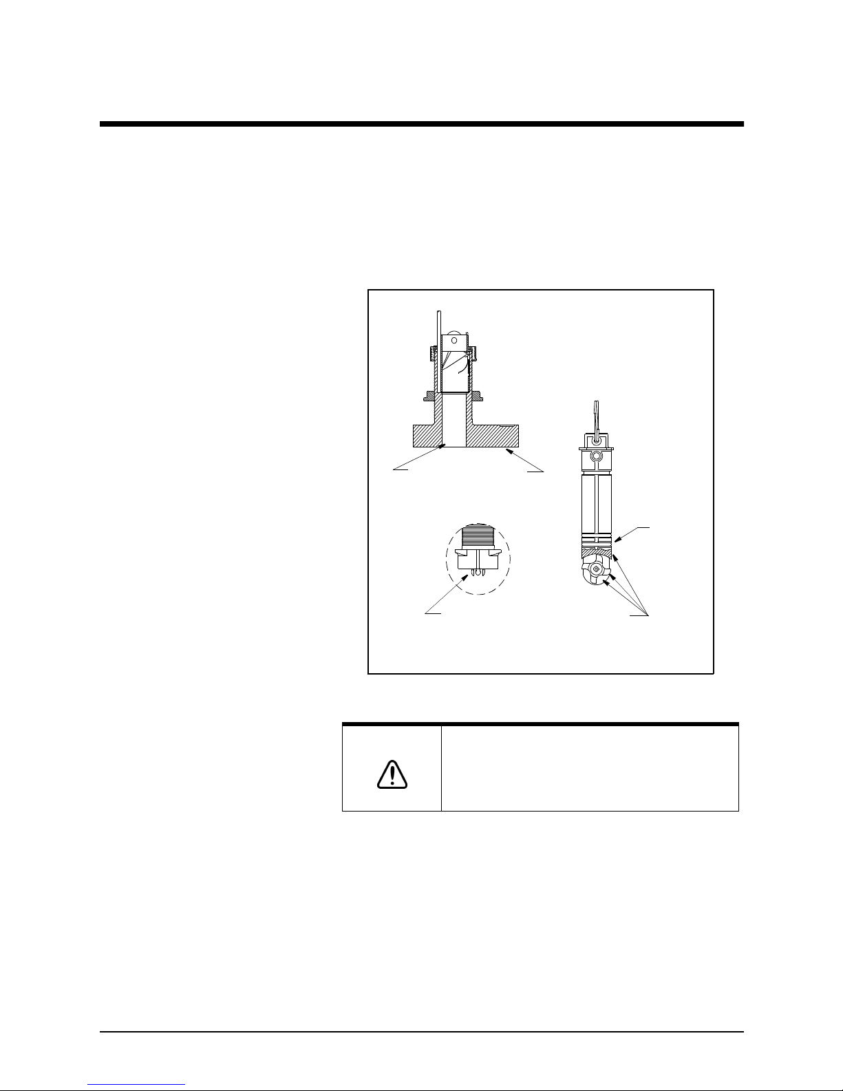
Using anti-fouling paint The transducer should be coated with water-based anti-fouling
paint to prevent aquatic growth.
Figure 4: Anti-fouling paint areas (for Airmar B44V)
Cleaning a transducer To clean the transducer of heavy debris or foul sea growth, use
a stiff brush or putty knife, but don’t scratch the surfaces.
Check the transducer every few weeks, maximum.
Use sanding sparingly, as repeated sanding may affect the
transducer’s performance at high speeds. For lighter cleaning,
the surface may be wet-sanded with #220 or finer wet/dry
sandpaper.
CAUTION!
Use special transducer paint. Other paints may
contain copper, which is conductive and can burn
out the transducer within minutes!
Anti-fouling paint (B44V shown)
Paint outside wall below the lower O-ring
including exposed end, paddle wheel cavity and paddle wheel
Paint exposed housing
lower
O-ring
and bore up 30 mm (1-1/4")
paddle wheel
insert
housing
detail
Page 18

SECTION TWO Installing the transducer
Page 12 490 INSTALLATION MANUAL, Revision B2
Page 19
490 INSTALLATION MANUAL, Revision B2 Page 13
SECTION THREE
Installing the
490
Safety
considerations
WARNING!
Be sure to turn the power off before starting the
installation. Further, it is highly recommended that
you keep the power off while you’re performing the
installation. If power is left on or turned on during
the installation, then fire, electrical shock, or other
serious injury may occur.
Be sure to ground the equipment to prevent
electrical shock and mutual interference.
Be sure that the voltage of the power supply is
between 10 and 30 volts DC. Connecting to the
wrong power supply can result in fire or damage to
equipment.
Be sure to use a 3-amp fuse. Using the incorrect
fuse can result in fire or damage to the 490.
CAUTION!
Keep the following safe compass distances from
the 490: 1.0 m standard, 0.8 m steering.
Page 20
SECTION THREE Installing the 490
Page 14 490 INSTALLATION MANUAL, Revision B2
System
components
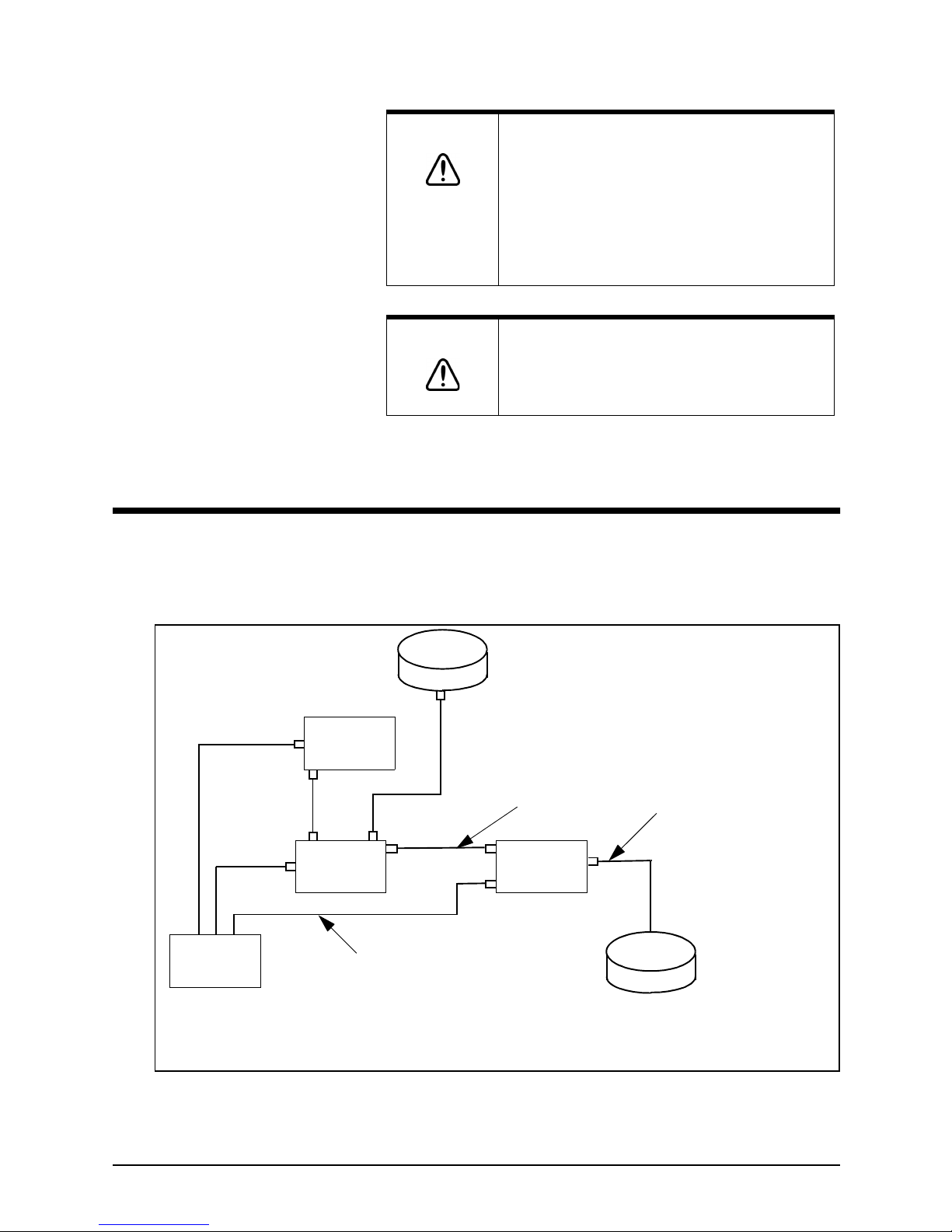
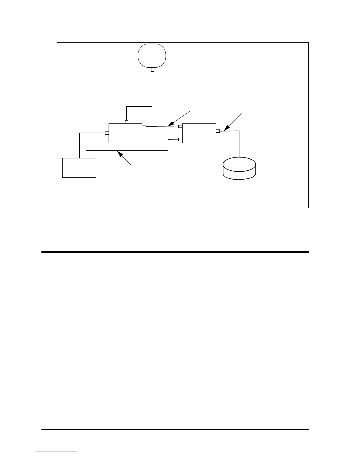
Figure 5 on page 14 shows a configured 961/962 echo sounder
system, and Figure 6 on page 15 shows a configured 957/958
echo sounder system.
Figure 5: 961/962 echo sounder system components
CAUTION!
Be sure that the 490 doesn’t interfere with any of
the on-board systems. Check all other systems to
ensure that their performance doesn’t degrade
when the 490 is turned on.
If the vessel is out of the water when the echo
sounder is turned on, the transducer may be
damaged.
CAUTION!
Do not open the 490. There are no serviceable
parts inside. Unauthorized tampering with the unit
will automatically void the warranty.
TRANSDUCER
10-FOOT CABLE
(NORTHSTAR-SUPPLIED)
SHIP’S POWER
NORTHSTAR
961/962
PROCESSOR
NORTHSTAR
961/962
DISPLAY
NORTHSTAR
490 ECHO
SOUNDER
GPS/DGPS
ANTENNA
DATA
INTERFACE
RECOMMENDED:
AIRMAR B250 1000-W TRANSDUCER
FOR THE 490-D
AIRMAR B44V/B744V 600-W TRANSDUCER
FOR THE 490-S
10-FOOT CABLE
(NORTHSTAR-SUPPLIED)
33-FOOT CABLE
(PART OF TRANSDUCER)
Page 21
SECTION THREE Installing the 490
490 INSTALLATION MANUAL, Revision B2 Page 15
Figure 6: 957/958 echo sounder system components
Choosing a
mounting
location
Before any drilling or cutting takes place, carefully choose a
mounting location for the 490 that meets the following criteria:
• where the transducer is more than four feet away from the
Northstar 961/962 or 957/958, to prevent mutual electrical
and magnetic interference
• where the transducer cable is kept securely away from
other wires
• where the path for running the required electrical cabling
is reasonably direct; keep in mind the different cable
lengths
• where the 490 won’t be exposed to water
TRANSDUCER
10-FOOT CABLE
(NORTHSTAR-SUPPLIED)
SHIP’S POWER
NORTHSTAR
957/958
NORTHSTAR
490 ECHO
SOUNDER
POWER AND DATA
INTERFACE
RECOMMENDED:
AIRMAR B250 1000-W TRANSDUCER
FOR THE 490-D
AIRMAR B44V/B744V 600-W TRANSDUCER
FOR THE 490-S
10-FOOT CABLE
(NORTHSTAR-SUPPLIED)
33-FOOT CABLE
(PART OF TRANSDUCER)
NORTHSTAR
2201 GPS
Page 22
SECTION THREE Installing the 490
Page 16 490 INSTALLATION MANUAL, Revision B2
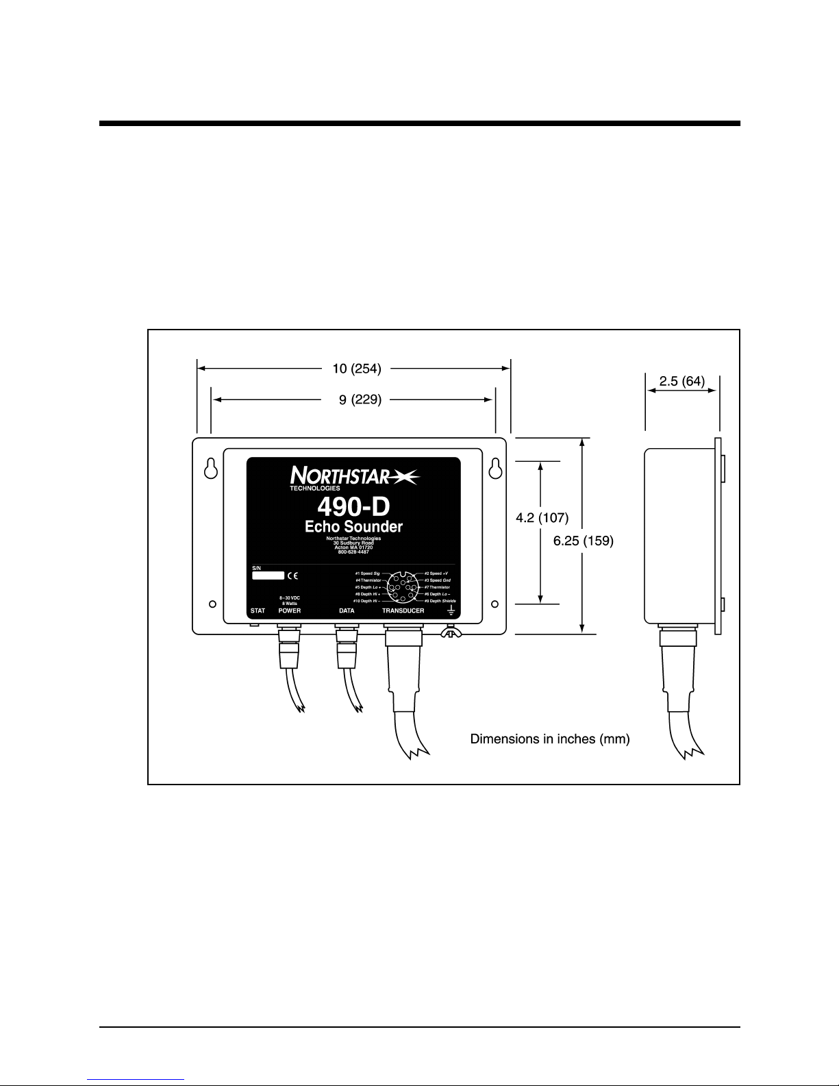
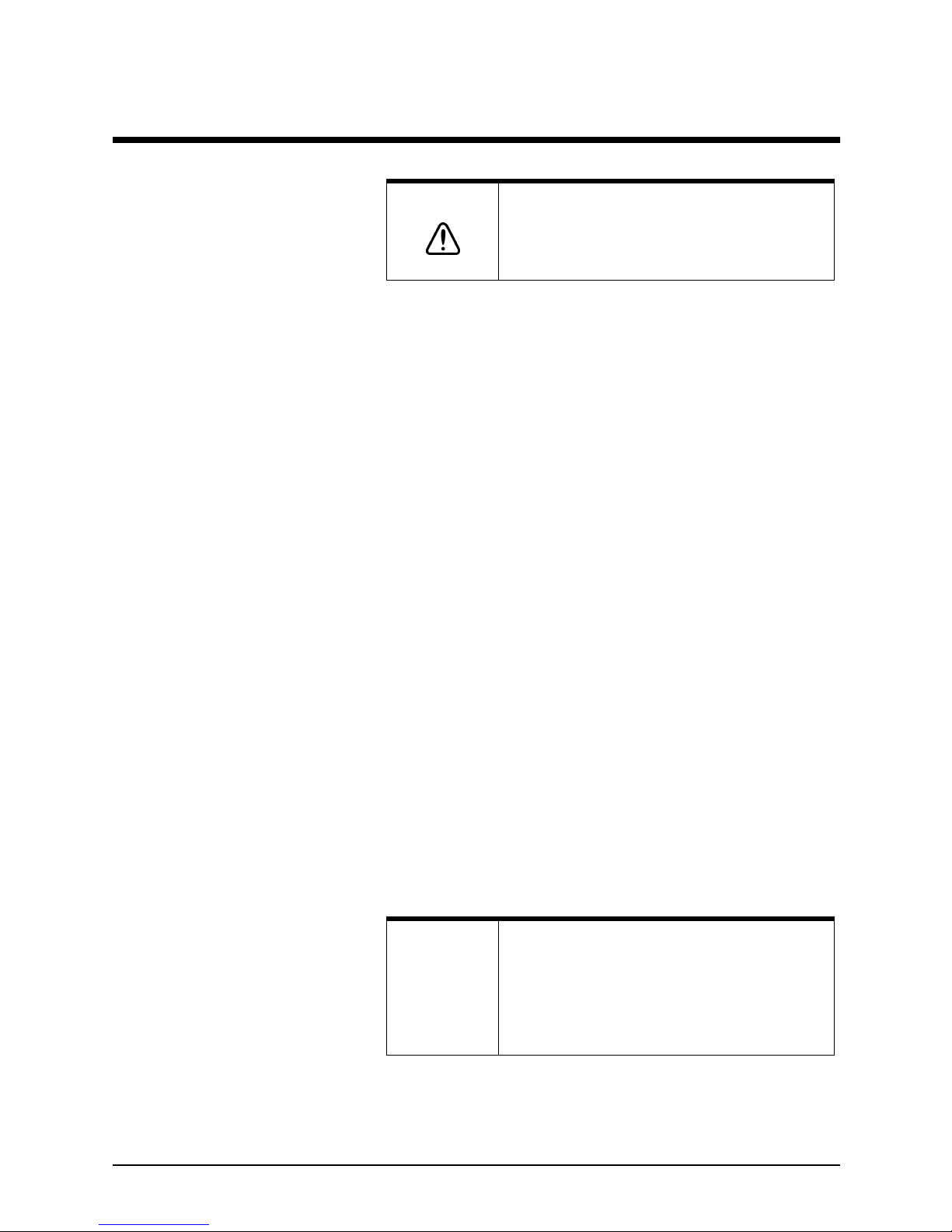
Mounting the 490 Figure 7 below shows the mounting dimensions for the 490.
The 490 may be mounted either horizontally or vertically.
The keyhole slots make installation in hard-to-reach areas
easier, but be sure to tighten all mounting screws securely.
Leave room for installing and removing cables, and be sure you
can see the STAT (status) indicator light. This light illuminates
when the 490’s power is on, and is helpful when
troubleshooting.
Figure 7: 490 mounting dimensions and connector locations
Page 23
SECTION THREE Installing the 490
490 INSTALLATION MANUAL, Revision B2 Page 17
Wiring the 490
The majority of installation problems are caused by shortcuts
taken with system cables. When installing the 490, be sure that
you:
• assemble connectors carefully
• don’t make sharp bends in the cables
• leave service and drip loops, so that moisture won’t run
down the cables and into the 490 or the 961/962 or 957/
958
• tie-wrap all cables to keep them secure
• if cables are shortened, lengthened (not recommended), or
re-terminated, seal all wiring splices
• prevent interference from the transducer cable
Electrical power
requirements
The 490 is a negative-ground system that is reverse-polarity
and overvoltage protected. The unit requires 10 to 30 VDC
power at 8 Watts.
Connecting the 490 to ship’s
power
The connection between ship’s power and the 490 requires the
10-foot (3-meter) power cable supplied by Northstar.
The wires in the power cable must be connected as follows
(black and white can be connected together at the power
source):
• Red → Positive (+) (fused lead)
• Black → Negative (–)
• Green → Ground (earth)
CAUTION!
Make sure that fuse or circuit-breaker protection is
provided at the power source.
NOTE:
The 490 should be grounded to the vessel to
eliminate interference. Secure either the green wire
or a ground wire from the 490’s grounding terminal
(on the far right side of the unit) to the vessel’s
nearest grounding point. Without an earth
grounding, performance may be degraded.
Page 24
SECTION THREE Installing the 490
Page 18 490 INSTALLATION MANUAL, Revision B2
Connecting the 490 to the
961/962
The connection between the 961/962 and the 490 requires the
10-foot (3-meter) data cable supplied by Northstar. The cable
connects to the P1 slot on the back of the 961/962.
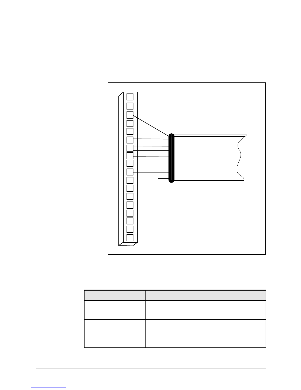
Figure 8 below illustrates the wiring at the 961/962 end of the
cable. Table 3 describes the pin’s functions.
Figure 8: Interface cable connection from 961/962 to 490
Violet
Black
Blue
Brown
Orange
White
Green
Red (not
connected)
961/962 P1 Connector Plug
(Wiring Side View)
Data Cable
16
17
18
13
6
5
4
3
2
1
14
15
11
10
9
8
7
12
Table 3: Cable connection between the 961/962 and 490
961/962 pin number 961/962 P1 signal name Cable wire color
9 Port 3 In (A) Blue
10 Port 3 In (B) Black
11 Ground Brown
12* Port 3 Out (A) Violet
12* Port 3 Out (A) White
Page 25
SECTION THREE Installing the 490
490 INSTALLATION MANUAL, Revision B2 Page 19
Connecting the 490 to the
957/958
The connection between the 957/958 and the 490 requires the
10-foot (3-meter) data cable supplied by Northstar. The cable
connects to the AUX port on the back of the 957/958.
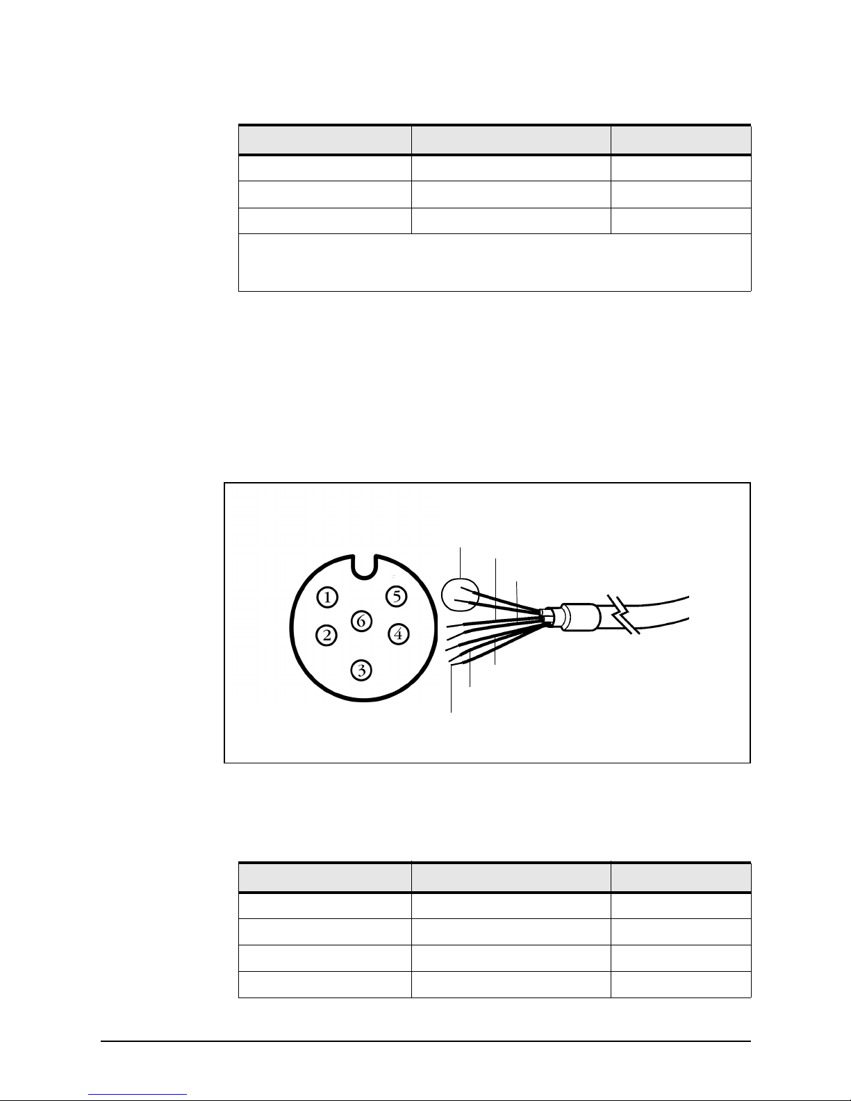
Figure 9 below illustrates the wiring for the 957/958 end of the
cable. Table 4 describes the pin’s functions.
Figure 9: Interface cable connection from 957/958 to 490
13 Port 3 Out (B) Orange
16 Ground Green
** Not connected Red
* Connector P1, pin 12 on the 961/962 requires two connections from the cable.
**The red wire is not connected on the 961/962 end, and should be insulated and capped.
Table 3: Cable connection between the 961/962 and 490 (cont.)
961/962 pin number 961/962 P1 signal name Cable wire color
Brown (1)
Green (1)
Black (3)
Violet (4)
Orange (5)
White (2)
Blue (6)
Table 4: Cable connection between the 957/958 and 490
957/958 pin number AUX port signal name Cable wire color
1* Shield/Gnd Brown
1* Remote On Gnd Green
2 Remote On input White
3 NMEA AUX In (B) Black
Page 26
SECTION THREE Installing the 490
Page 20 490 INSTALLATION MANUAL, Revision B2
Connecting the 490 to a
transducer
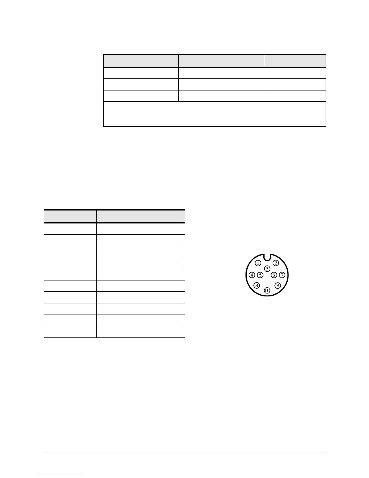
Figure 10 below shows how to terminate the transducer cable
for connection to the 490. Pay close attention to whether you’re
wiring a 490-S or a 490-D. See also the Transducer Connector
Instructions (GM492).
4 NMEA AUX Out (A) Violet
5 NMEA AUX Out (B) Orange
6 NMEA AUX In (A) Blue
* Pin 1 on the 957/958 AUX port requires two connections from the cable.
The red wire is not connected on the 957/958 end, and should be insulated and capped.
Table 4: Cable connection between the 957/958 and 490 (cont.)
957/958 pin number AUX port signal name Cable wire color
Table 5: 490-to-transducer connector pin
wiring
Pin number Connector
1 Speed signal
2 Speed +V
3 Speed ground
4 Thermistor (temperature)
5 Depth low+ (unused on 490-S)
6 Depth low- (unused on 490-S)
7 Thermistor (temperature)
8 Depth high+
9 Depth shields
10 Depth high-
Figure 10: Wiring of transducer cable
(solder-cup side of connector shown)
Page 27

SECTION THREE Installing the 490
490 INSTALLATION MANUAL, Revision B2 Page 21
Powering up,
setting up, and
powering down
the 490
Turning the 490 on For the 961/962
This section assumes that the 490, Northstar 961/962, and
transducer are now all properly connected.
To use the 490 echo sounder, the 961/962 must be running
software version 3.0 or higher. If not, contact Northstar to
obtain the upgrade CD. To install the upgrade, follow the steps
on the back of the jewel box.
Turning on the 961/962 processor automatically turns on the
490 (be sure your vessel is in the water). To turn the 961/962
on, briefly press its
PWR key.
You must set the 961/962’s Port 3 to “490”:
1. Press
STAR to display the SERVICE MENU screen.
2. Press PORT SETUP.
3. Press PORT 3.
4. Set the FORMAT option to 490.
The STAT (status) indicator light on the 490 glows steady green
when the 490’s power is on.
For the 957/958
This section assumes that the 490, Northstar 957/958, and
transducer are now all properly connected. Turning on the 957/
958 automatically turns on the 490 (be sure your vessel is in
the water). To turn the 957/958 on, briefly press its
PWR key.
You must set the 957/958’s AUX port to “490”:
1. Press the
STAR key to display the OPTIONS/SERVICE
INFO screen, then press the
PORT SETUP OPTIONS key.
2. Set the AUX PORT option to 490, then press the ENTER
key.
The STAT (status) indicator light on the 490 glows steady green
when the 490’s power is on.
Page 28
SECTION THREE Installing the 490
Page 22 490 INSTALLATION MANUAL, Revision B2
Setting up the echo sounder You’ll need to set the echo sounder display options on the 961/
962 or 957/958’s ECHO SOUNDER SETUP screen. Press the
STAR key to display this screen and set these options. For
details, see the Northstar 490 Echo Sounder Operations Manual
(GM490).
Turning the 490 off To turn off the 490, turn off the 961/962 or 957/958 by pressing
and holding
PWR until the screen goes dark. The 490 will turn
off automatically.
Installation-test
checklist
1. Make sure the vessel is in the water.
2. To test the system after installation, turn on the 961, 962,
or 957/958 and confirm that power is on with no errors. If
echo sounder data isn’t moving across the ECHO screen
from right to left, see ”Troubleshooting common 490
installation problems” on page 23.
CAUTION!
If the vessel is out of the water when the echo
sounder is turned on, the transducer may be
damaged. Perform all tests on the with the vessel in
the water.
Page 29

490 INSTALLATION MANUAL, Revision B2 Page 23
SECTION FOUR
Troubleshooting
and servicing
the 490
Troubleshooting
common 490
installation
problems
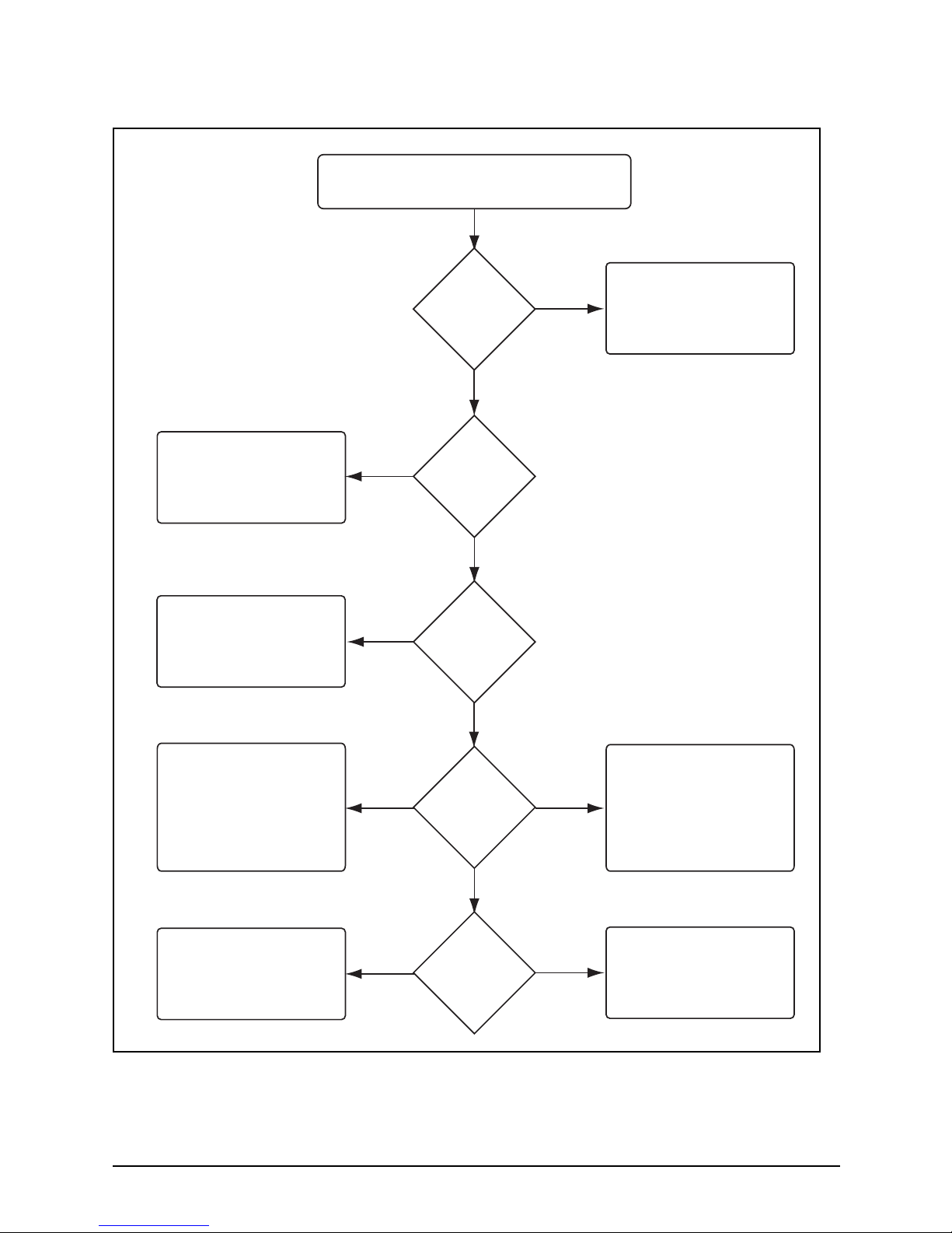
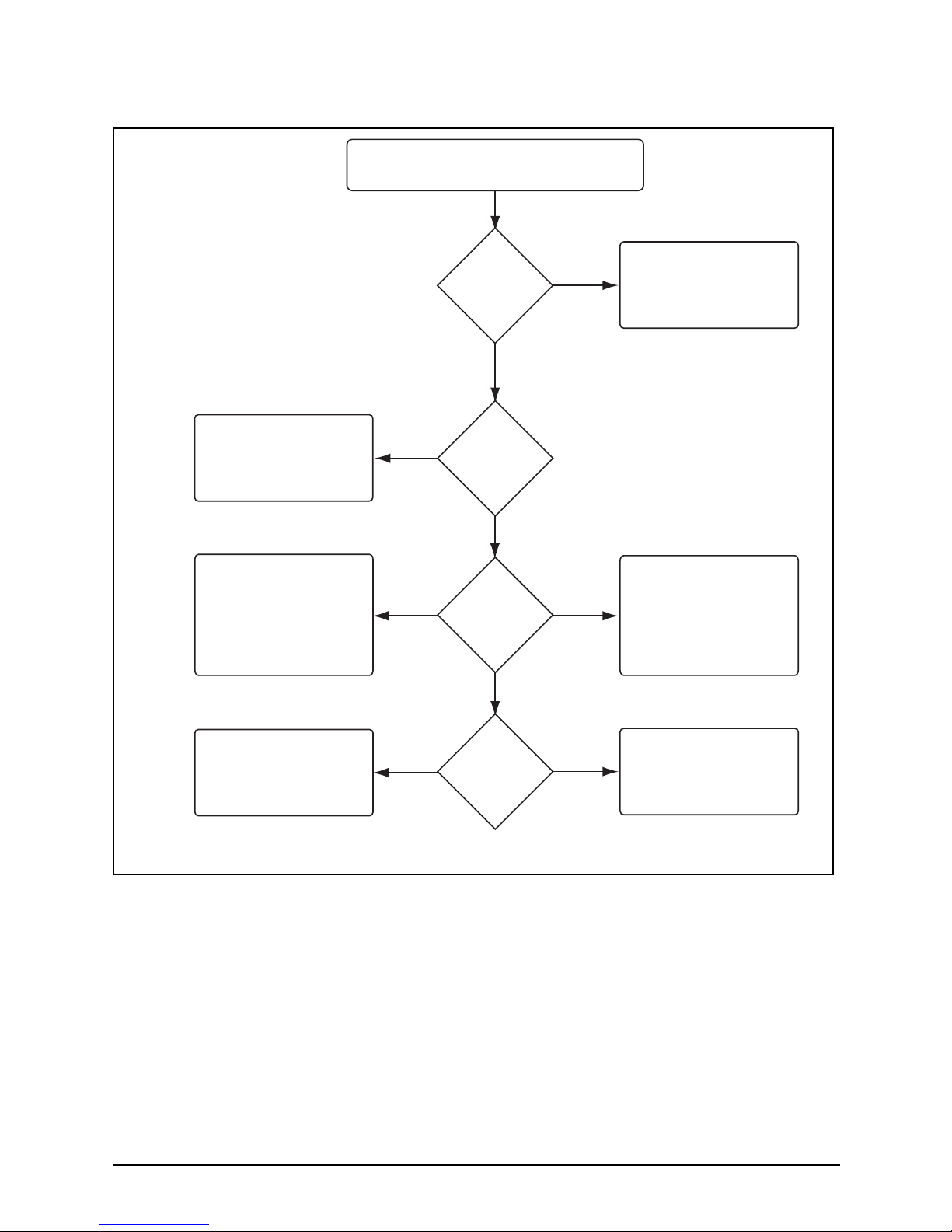
Typical problems you may encounter either during or after the
490 installation process are outlined in Figure 11 on page 24
and Figure 12 on page 25.
In the 961/962, the diagnostics screen may also help pinpoint
the problem.
Page 30
SECTION FOUR Troubleshooting and servicing the 490
Page 24 490 INSTALLATION MANUAL, Revision B2
Figure 11: 961/962 echo sounder system troubleshooting
No echoes displayed when STAR key is pressed.
Is the
961/962
software
Version 3.0 or
greater?
Has
NMEA Port 3
been configured
for the 490?
Check
the 490's STAT
indicator
What
is the flash
rate of the STAT
indicator?
Is the
Advance
Speed set to
zero?
YES
YES
YES
NO
NO
NO
OFF
STEADY
ON
FLASHING
ONCE
PER
SECOND
FOUR
TIMES
PER
SECOND
Contact Northstar Service to
upgrade to the latest version
of 961/962 software.
Change the Advance Speed
setting.
Configure NMEA Port 3 for
the 490. See the 490
Operations Manual (GM490)
for instructions.
1. Check fuses and circuit
breakers
2. Check power to 490 with
a voltmeter.
3. Verify that the data cable
between the 961/962 and
the 490 is properly wired
and connected.
1. Check transducer
connector for the
proper wiring.
2. If wiring is correct,check
transducer impedance
with an ohmmeter.
3. If the transducer is open
or shorted, replace it
There's a hardware problem
with the 490.
The 490 and the 961/962
aren't communicating properly.
Check the wiring of the data
cable between the 961/962
and the 490.
Page 31
SECTION FOUR Troubleshooting and servicing the 490
490 INSTALLATION MANUAL, Revision B2 Page 25
Figure 12: 957/958 echo sounder system troubleshooting
No echoes displayed when STAR key is pressed.
Has
957 Aux Port
been configured
for the 490?
Check
the 490's STAT
indicator
What
is the flash
rate of the STAT
indicator?
Is the
Advance
Speed set to
zero?
Ye s
No
Ye s
No
Off
Steady On
Flashing
Once per
Second
Four Times
per Second
Change the Advance Speed
setting.
Configure 957 Aux Port for
the 490. See the 490
Operations Manual (GM490)
for instructions.
1. Check fuses and circuit
breakers.
2. Check power to 490 with
a voltmeter.
3. Verify that the data cable
between the 957 and
the 490 is properly wired
and connected.
1. Check transducer
connector for the
proper wiring.
2. If wiring is correct,check
transducer impedance
with an ohmmeter.
3. If the transducer is open
or shorted, replace it
There's a hardware problem
with the 490.
The 490 and the 957 aren't
communicating properly.
Check the wiring of the data
cable between the 957 and
the 490.
Page 32
SECTION FOUR Troubleshooting and servicing the 490
Page 26 490 INSTALLATION MANUAL, Revision B2
Getting technical
support
After you’ve followed the instructions in this manual, if you
need additional technical or operations support for the 490, or
if you have any other service-related questions, you can
contact either your dealer or the Northstar Service Department.
You can reach Northstar’s Service Department by email, fax,
U.S. mail, or phone as described in Table 6 below.
Please be as complete and accurate as possible when describing
the problem so that a service technician can research the
problem and provide the quickest response.
Northstar’s Service Department is available between 9:00 AM
and 5:00 PM Eastern Time, Monday through Friday, excluding
major holidays.
If you have questions about purchasing parts or finding an
authorized Northstar dealer, or if you want basic product
information and brochures, contact the Northstar Sales
Department as described in the table below.
You can email the
Northstar Service
Department directly from
Northstar’s website
(www.NorthstarNav.com).
Here, you also can access
additional technical
information under either
the Manuals
link (you can
download manuals in PDF
f
orm) or Support link.
NOTE:
Please have the following items available when you
contact Northstar’s Service Department:
• the 490’s serial number, located on the top of
the unit
• the transducer manufacturer’s name and the
transducer’s model and part number
Table 6: Contacting Northstar
Email:
Service: [email protected]
Sales: [email protected]
Fax:
Service: 978/897-1595
Sales: 978/897-7241
Telephone:
Main number: 978/897-6600 or 800/628-4487
Sales: 978/897-0770
Service: 978/897-6600
U.S. mail:
30 Sudbury Road
Acton, MA 01720
Page 33

SECTION FOUR Troubleshooting and servicing the 490
490 INSTALLATION MANUAL, Revision B2 Page 27
Hearing from you Your feedback is important and helps Northstar ensure that this
manual is a valuable resource for all marine technicians. Send
your questions, comments, or suggestions about this manual
to:
Ordering
replacement
parts
To order spare parts or replacement/missing parts, call the
Northstar Sales Department at 978/897-0770.
Servicing the 490 Repair of the 490 is performed only at the Northstar factory.
Service includes a complete hardware and software check-out.
For a system under warranty, shipping charges to the factory
are the only cost for factory repair. The repaired 490 will be
returned via prepaid economy ground freight (units returned
overseas are chargeable).
The 490 and any accessories returned for warranty repair that
are determined to be without fault are subject to a handling
charge.
Website:
www.NorthstarNav.com (you can send email to
Northstar directly from this site)
Table 6: Contacting Northstar (cont.)
NOTE:
Field repairs are not authorized and will void the
warranty!
For transducer service, including parts and repairs,
please contact the transducer manufacturer.
Page 34
SECTION FOUR Troubleshooting and servicing the 490
Page 28 490 INSTALLATION MANUAL, Revision B2
Returning a 490
for service
The 490 is covered by a two-year hardware-only warranty,
which, in summary, states that if the 490 is returned to the
Northstar factory by the owner or dealer during the warranty
period, Northstar will repair or replace, free of charge, any part
found to be defective due to faulty materials or workmanship if
the system has been properly installed and hasn’t been abused.
See the Limited Warranty Policy at the front of this manual for
further details. The only cost to the owner will be the one-way
shipping charges and any associated charges that may be
imposed by the dealer. If you have overnight or second-day
shipping requirements, before shipping the 490, please call
Northstar for turnaround time, freight charges, and payment
arrangements.
The 490 should be shipped only in a properly designed carton
with packing material. Shipments to the Northstar factory
should be made to the following address:
Northstar Technologies
Service Department
30 Sudbury Road
Acton, MA 01720 USA
Before returning the 490 to
the Northstar factory, to
prevent delays it is critical
that you first obtain a
Return Materials
Authorization (RMA)
number from the Northstar
Service Department. If the
490 was purchased through
a dealer, call the dealer
with the 490 serial number
so they can help you get an
RMA number. The 490’s
serial number can be found
on the label at the top of the
490.
Shipments without a
proper RMA number will
not be accepted!
NOTE:
Return the transducer to its manufacturer, not to
Northstar.
Page 35
490 INSTALLATION MANUAL, Revision B2 Page 29
APPENDIX A
Technical
specifications
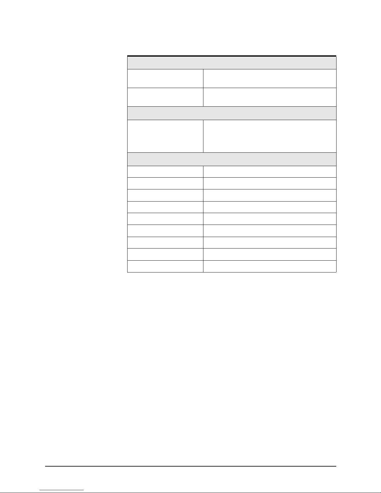
Table 7: 490 technical specifications
Performance characteristics
Frequencies 50 and 200 kHz
Output power 1000 watts (490-D); 600 watts (490-S)
Pulse lengths 0.1 to 2 ms
Pulse repetition rate 30 to 600 pulses/min
Alarms Fish, bottom, and temperature
Update rate 10 Hz maximum (depends on water depth)
Zoom modes Marker, bottom lock, bottom lock/center, bottom
Auto modes Fishing or cruising
Navigation data Shown on bottom of screen
Display modes Single/dual frequency, split-screen, four zoom
modes, A-Scope
Physical characteristics
Dimensions 10 x 6.25 x 2.5 inches (including backplate)
Weight 2 pounds
Page 36
APPENDIX A Technical specifications
Page 30 490 INSTALLATION MANUAL, Revision B2
Environmental characteristics
Temperature -25°C to +60°C operating temperature
-55°C to +90°C storage temperature
Standards Waterproof, sealed design meets the following:
EN60529 IP65; EN60945 emissions; CE
Electrical characteristics
10 to 30 VDC, 8 Watts, reverse polarity and
overvoltage protection
Transducer outputs protected against open circuit/
short circuit
Manual controls
Gain 0 to 75 db
Clutter 0 to 9
Signal level 0 to 5
Noise limiter ON/OFF
White level Background color
Range up to 2400 feet (800 meters)
Advance speed 1/8 to 2/1
Depth units Feet, meters, fathoms
Installation calibrations Speed, temperature, gain, transducer depth/offset
Table 7: 490 technical specifications (cont.)
Page 37

490 INSTALLATION MANUAL, Revision B2 Page 31
Glossary
cavitation The formation of bubbles, which may negatively impact a
transducer’s readings by reducing its ability to put energy into
the water.
deadrise The rise of the bottom of a vessel above a horizontal line at the
center of the vessel; that is, the slope of the hull away from the
horizontal.
echo sounder An instrument that uses sound waves to measure the depth of
a body of water or an object (such as a school of fish) below the
water’s surface.
fairing block A block used to create a horizontal surface for mounting a
thru-hull transducer when the vessel’s deadrise is more than 5
degrees.
transducer The device mounted through the hull to send and receive
ultrasonic beams that determine seabed conditions and locate
fish. Essentially, a transducer is an energy converter, which
changes electricity to sound (send) and sound to electricity
(receive).
Page 38

Glossary
Page 32 490 INSTALLATION MANUAL, Revision B2
water column An imaginary column through the water created by the path of
a single transducer ping and its echoes.
Page 39

490 INSTALLATION MANUAL, Revision B2 Page 33
Index
A
Airmar Technology Corporation 7
C
Cable
490 and 957
19
490 and 961/962 18
490 and ship’s power 17
Cautions
installation
2, 5, 6, 13
interference with 490 13
tampering with the 490 14
transducer 5, 7, 22
troubleshooting the 490 22
wiring the 490 17
E
Echo sounder
components of system
1, 14
definition of 31
installation. See Installation, 490
serial number
28
setup options 22
specifications 29
STAT indicator light 16, 21
turning off 22
turning on 21
wiring 17
Electrical power, requirements 17
F
Fairing block, definition of 31
G
GEM Electronics Company 7
I
Installation
490
cautions
2, 13, 14, 17, 22
connecting to 957 19
connecting to 961/962 18
connecting to ship’s power 17
electrical power requirements 17
general considerations 2
mounting dimensions 16
mounting location 15
overview 13
safety considerations 13
troubleshooting 23
wiring 17
transducer
cautions
5, 7, 22
cavitation 8
hull thickness limits 8
noise problems 8
Page 40

Page 34 490 INSTALLATION MANUAL, Revision B2
preferred mounting location 8
recommended incline angle 10
thru-hull installation with a fairing block 10
M
Maintenance, transducer 11
N
Northstar 490 Echo Sounder. See Echo sounder
Northstar 957 GPS/WAAS Chart Navigator
1, 3, 15, 21
Northstar 961/962 GPS Chart Navigator 1, 3, 15, 21
Northstar Technologies
feedback on manuals
27
sales department 26
service department 26
website. See Website addresses
P
Parts, ordering. See Technical support
S
Safety considerations
490
13
transducer 5
Service. See Technical support
Software upgrades, obtaining
21
Specifications 29
STAT (status) indicator light 16, 21
T
Technical support
contacting Northstar
26
ordering parts 27
repairing the 490 27
repairing the transducer 27
returning the 490 28
Transducer
definition of
31
installation. See Installation, transducer
maintenance. See Maintenance, transducer
mounting. See Installation, transducer
purchasing
7
recommended 6
service, parts and repair 27
Troubleshooting
diagnostics screen
23
flow chart 25
installation checklist 22
installation problems 23
U
Upgrades, obtaining software 21
W
Warranty for the 490 3, 28
Water column, definition of 32
Website addresses
Airmar Technology Corporation
7
Northstar Technologies 7, 26, 27
 Loading...