


Northern Lights 281PSL1500, 281PSL1501, 281PSL1502, 282PSL1503, 282PSL1504 Manual
...MAGNAPLUS® GENERATOR
280–430 Frame
Installation, Operation,
and Maintenance Manual
Marathon Electric Mfg. Corp. A Subsidiary of Regal-Beloit Corp.
P.O. Box 8003 Wausau, WI 54402-8003 Phone: (715) 675 3359 Fax: (715) 675 8026 www.marathonelectric.com

CONTENTS |
|
|
Safety |
|
2 |
Receiving and Storage |
|
2 |
Principles of Operation |
|
3 - 4 |
Installation |
|
4 - 6 |
Wiring Connections |
|
6 - 9 |
Operation |
9 |
- 10 |
Maintenance |
10 |
- 11 |
Testing |
11 |
- 12 |
Service |
12 |
- 14 |
Troubleshooting |
14 |
- 17 |
Specifications |
|
18 |
Parts List & Recommended Spare Parts |
19 |
- 20 |
|
|
|
SAFETY
PLEASE REMEMBER SAFETY FIRST. If you are not sure of the instructions or procedures contained herein, seek qualified help before continuing.
This service manual emphasizes the safety precautions necessary during the installation, operation, and maintenance of your MagnaPLUS generator. Each section of this manual has caution and warning messages. These messages are for your safety, and the safety of the equipment involved. If any of these cautions or warnings are not readily understood, seek clarification from qualified personnel before proceeding.
Before any service work is done, disconnect all power sources and lock out all controls to prevent an unexpected start-up of the generator set driver. Proper grounding (earthing) of the generator frame and distribution system in compliance with local and national electrical codes and specific site requirements must be provided. These safety precautions are necessary to prevent potential serious personal injury, or even death.
The hazards associated with lifting or moving your MagnaPLUS generator are pointed out in the installation and maintenance sections. Incorrect lifting or moving can result in personal injury or damage to the unit.
Prior to start-up of the unit ensure that all generator leads are properly connected to the generator link board located inside the connection box. Always assume that there will be voltage present at the generator terminals whenever the generator's shaft is rotating, and proceed accordingly. Residual voltage is present at the generator terminals and at the automatic voltage regulator panel connections even with the regulator fuse removed. Caution must be exercised, or serious injury or death can result.
This manual is not intended to be a substitute for properly trained personnel. Installation and repairs should only be attempted by qualified, trained people. The cautions and warnings point out known conditions and situations that are potentially hazardous. Each installation may well create its own set of hazards
When in doubt, ask. Questions are much easier to handle than mistakes caused by a misunderstanding of the information presented in this manual.
RECEIVING AND STORAGE
RECEIVING AND STORAGE
Upon receipt of the generator, it is recommended that it be carefully examined for possible shipping damage. The generator was given to the freight carrier in good condition; thus, the carrier is responsible for the product from the factory dock to the destination. Any damage should be noted on the freight bill before accepting the shipment. Any claims for damage must be promptly filed with the delivering carrier.
UNPACKING AND HANDLING
Carefully read all instruction tags shipped with the unit. When lifting, attach an overhead crane to the lifting lug(s) on the generator frame. Apply lifting forces in a vertical direction. When transporting single bearing generators, the generator’s rotor must be adequately supported to prevent damage.
WARNING
THE LIFTING LUG(S) ON THE GENERATOR ARE DESIGNED TO SUPPORT THE GENERATOR ONLY. DO NOT LIFT A COMPLETE GENERATOR AND DRIVER ASSEMBLY BY MEANS OF LIFTING LUG(S) ON THE GENERATOR. PERSONAL INJURY OR EQUIPMENT DAMAGE MAY RESULT.
STORAGE
In the event that the generator is not immediately installed on its prime mover, it is recommended that the unit be stored indoors in a clean, dry area which is not subject to rapid changes in temperature and humidity. If the generator is stored for a long period of time, the generator should be tested, cleaned and dried as required before being put into service. See the maintenance section of this manual for further information. If the unit has been stored in an area where it has been subject to vibration, it is recommended that the bearing(s) be inspected and replaced as necessary.
2

PRINCIPLES OF OPERATION
PMG (optional) |
Rotating Assembly |
|
|
||
PMG Field |
Exciter Field |
Exciter Armature |
Main Field |
Main Armature |
L1 |
(rotor) |
(stator) |
(rotor) |
(rotor) |
(stator) |
|
N |
(+) |
|
|
|
|
|
|
(+) |
|
|
|
|
DC |
|
DC |
|
L2 |
S |
(in) |
|
(in) |
|
|
|
|
|
|
|
|
|
(-) |
|
(-) |
|
|
|
|
|
|
L3 |
|
PMG |
|
3 Phase AC (out) |
|
3 Phase AC (out) |
|
|
|
|
|
|
|
Armature |
|
|
|
|
|
(stator) |
|
|
Rotating Rectifier Assembly |
|
|
|
|
|
3 Phase -- Full Bridge |
|
|
|
Exciter Field Power |
Input Power -- Single Phase |
|
||
|
|
(DC out) |
(shunt powered regulator) |
|
|
PMG Input Power (optional) |
|
Automatic |
|
|
|
|
Voltage |
|
|
||
|
(1 phase, 300/250 hertz) |
|
Regulator |
|
|
Sensing Input -- Single Phase
3 phase (optional)
FIGURE 1 -- MagnaPLUS Circuit Diagram
FIGURE 2 -- Typical MagnaPLUS Layout Diagram
3

PRINCIPLE OF OPERATION
MagnaPLUS generators are a brushless, self excited, externally voltage regulated, synchronous AC generator. The generator is made up of six major components: main stator (armature), main rotor (field), exciter stator (field), exciter rotor (armature), rectifier assembly, and voltage regulator. In understanding the above terminology, note the following: stators are stationary, rotors rotate, a field is an electrical input, and an armature is an electrical output. These system components are electrically interconnected as shown in figure 1 and physically located as shown in figure 2.
The generator’s exciter consists of a stationary field and a rotating armature. The stationary field (exciter stator) is designed to be the primary source of the generator’s residual magnetism. This residual magnetism allows the exciter rotor (armature) to produce AC voltage even when the exciter stator (field) is not powered. This AC voltage is rectified to DC by the rotating rectifier assembly and fed directly to the main rotor (field). As the generator shaft continues to rotate, the main rotor (field) induces a voltage into the generator's main stator (armature). At rated speed, the main stator’s voltage produced by the residual magnetism of the exciter allows the automatic voltage regulator to function. The regulator provides voltage to the exciter resulting in a build-up of generator terminal voltage. This system of using residual magnetism eliminates the need for a special field flashing circuit in the regulator. After the generator has established the initial residual voltage, the regulator provides a controlled DC field voltage to the exciter stator resulting in a controlled generator terminal voltage.
Voltage Regulation
In the standard configuration (shunt excited), the automatic voltage regulator receives both its input power and voltage sensing from the generator's output terminals (See Figure 1). With the optional PMG configuration, the regulator receives input power from the PMG. The regulator automatically monitors the generator's output voltage against an internal reference set point and provides the necessary DC output voltage to the exciter field required to maintain constant generator terminal voltage. The generator's terminal voltage is changed by adjusting the regulator's reference set point. Consult the regulator manual for specific adjustment and operating instructions.
MOTOR STARTING
When a motor is started, a large surge of current is drawn by the motor. This starting current is equivalent to the motors locked rotor or stall current and is 5 to 10 times normal full load current. When the generator supplies this in-rush of starting current, the generator voltage dips temporarily. If the motor is too large for the generator, the generator’s voltage dips greater than 30 percent. This may result in the motor starter de-energizing or the motor stalling. MagnaPlus generators generally supply .3 to .4
horsepower per generator KW in motor starting capability. For specific data contact Marathon Electric.
PARALLEL OPERATION
All MagnaPlus generators are built with 2/3 pitch main stator windings and full amortisseur (damper) windings. These features make the MagnaPlus generators suitable for parallel operation when equipped with the proper voltage regulators and voltage regulator accessories. Consult with the factory for further information relative to parallel operations.
NONLINEAR LOADING
Solid state electronic control devices (variable frequency drives, precision motor controls, battery chargers, etc.) utilize electronic switching circuits (thyristors, SCRs, Diodes, etc.). These switching circuits introduce high frequency harmonics which distort the normal wave form of the generator. This creates additional heat in the generator windings and may cause the generator to over-heat. Problems which can occur are not limited to the generator. Poor wave shape may adversely effect various loads connected to the generator. Consult Marathon Electric for further information relative to nonlinear loads.
INSTALLATION
PREPARATION FOR USE
Although the generator has been carefully inspected and tested in operation prior to shipment from the factory, it is recommended that the generator be thoroughly inspected. Check all bolts for tightness and examine the insulation on lead wires for chafing prior to proceeding with installation. Remove all shipping tapes, bags, skids and rotor support blocking. For two bearing units, rotate the shaft by hand to ensure that it rotates smoothly without binding.
4
WARNING
DISABLE AND LOCKOUT ANY ENGINE CRANKING DEVICES BEFORE ATTEMPTING TO INSTALL OR SERVICE THE GENERATOR. FOR ELECTRIC START SETS, DISCONNECT THE CRANKING BATTERY. FOR AIR START, DISCONNECT THE AIR SUPPLY. FOR MOTOR GENERATOR SETS, OPEN THE POWER SUPPLY TO THE DRIVE MOTOR. FAILURE TO COMPLY WITH THESE SAFETY PROCEDURES COULD RESULT IN SEVERE PERSONAL INJURY OR EQUIPMENT DAMAGE.
NEVER "BAR OVER" THE ENGINE GENERATOR SET USING THE GENERATOR'S FAN. THE FAN IS NOT DESIGNED FOR THIS PURPOSE. BARRING OVER THE SET WITH THE FAN COULD DAMAGE THE FAN AND RESULT IN PERSONAL INJURY OR EQUIPMENT DAMAGE.
GENERATOR MOUNTING
Single Bearing Units.
Single bearing units are provided with an SAE flywheel housing adapter flange and flexible drive discs. Coupling the generator's shaft to the engine flywheel is accomplished with special steel drive discs bolted to the shaft. In addition to the drive discs, there may be a hub spacer, spacer discs, or a combination of hub spacer and spacer discs inserted between the drive discs and the shaft to achieve the proper shaft extension ("G" dimension per SAE J620c). Holes are provided in the periphery of the coupling discs which correspond to tapped holes in the prime mover's flywheel. The outside diameter of the drive discs fit in a rabbet in the flywheel so that concentricity is assured.
Grade 8 place bolts and hardened washers are recommended to mount the drive discs to the flywheel. DO NOT USE SPLIT TYPE LOCK WASHERS. Split lock washers when biting into the drive disc cause stress risers which may result in the disc fracturing.
The SAE flywheel housing adapter ring and the engine flywheel housing are designed to match each other with no further alignment necessary. Use grade 5 or greater mounting bolts. MagnaPLUS generator frames are constructed with two or three bolt holes per foot. The feet should be shimmed where necessary to obtain solid contact with the sub-base. With the frame securely bolted to the engine flywheel housing, there is no side thrust or pull on the generator frame, thus no real need to secure the feet with more than one bolt per foot.
GENERATOR MOUNTING
Two Bearing Generators -- Direct Drive
Two bearing generators are provided with a keyed shaft extension. For direct drive generators, the assembler furnishes a flexible coupling which is installed between the
driver and the generator's shaft. Aligning the generator and its driver as accurately as possible will reduce vibration, increase bearing life, and ensure minimum coupling wear. It may be necessary to shim the generator feet for proper support and alignment. Secure the feet of the generator with grade 5 or greater bolts through the holes provided in the mounting feet. Consult the coupling manufacturer's instructions for alignment specifications and procedures.
GENERATOR MOUNTING
Two Bearing Units -- Belt Driven
Two bearing MagnaPLUS generators can be belt driven provided belts are sized and applied correctly. Please refer to your supplier of belts and sheaves for correct sizing and tensioning specifications. A bearing life calculation should be performed. Marathon Electric recommends a minimum B-10 life of 40,000 hours. If cog type belts are used, a vibration may be introduced which could lead to premature failure of the bearings.
END PLAY TESTING
Refer to the engine manual for recommended end play specifications and measurement procedures. If end play is not to specification, it is an indication that the generator shaft is not moving freely in the assembly, and normal life of the thrust bearing could be impaired. Probable causes of this problem are:
1. Improper seating of drive discs in the flywheel resulting in misalignment.
2.Improper mating of generator frame to engine flywheel housing resulting in misalignment.
3.Improper "G" dimension per SAE J620c on either the engine or generator.
TORSIONAL VIBRATION
Torsional vibrations are generated in all rotating shaft systems. In some cases, the amplitude of these vibrations at critical speeds may cause damage to either the generator, its driver, or both. It is therefore necessary to examine the torsional vibration effect on the entire rotating system. IT IS THE RESPONSIBILITY OF THE GENERATOR SET ASSEMBLER TO ASSURE THE TORSIONAL COMPATIBILITY OF THE GENERATOR AND ITS DRIVER. Drawings showing pertinent dimensions and weights of the rotating assembly will be supplied by Marathon Electric upon request.
5
ENVIRONMENTAL CONSIDERATIONS
The MagnaPLUS generator is designed for heavy duty industrial applications; however, dirt, moisture, heat and vibration are enemies of rotating electrical machinery. Excessive exposure to the elements may shorten generator life. The temperature of the cooling air entering the intake openings of the generator should not exceed the ambient temperature shown on the generator’s nameplate. Generators intended for outdoor application should be protected with housings having adequate ventilation. Although the standard insulation systems are moisture and humidity resistant, space heaters are recommended for extreme conditions. If the generator is to be installed in an area where blowing sand and dust are present, the enclosure should be fitted with filters. Filters reduce erosion on the generator's insulation by blocking high velocity abrasive particles generated by the flow of cooling air through the generator. Consult the factory for appropriate filters and generator deratings required.
WIRING CONNECTIONS
Wiring of the generator and accessories should be done in accordance with good electrical practices. Follow government, industry and association standards.
The generator conduit box construction allows cable entry from multiple sides. A hole saw or other appropriate tool may be used to provide for conduit entrance. Protect the
interior of the generator from shavings when drilling or sawing. An approved connector must be used in conjunction with the conduit. To minimize the transmission of vibration, it is essential that flexible conduit be used for all electrical entrance to the generator conduit box.
All MagnaPLUS generators are equipped with link boards (terminal strips) for both internal and external connections. All connections made to the studs of the link board should be made with high quality ring terminals. Ring terminal sizes are: 6 mm (280 Series Frames) and 10 mm (360 and 430 Series Frames). Torque link board connections to the following specifications: 280 frame -- 5.4 NM (4 Ft Lb); 360 & 430 frame -- 27 NM (20 Ft Lb).
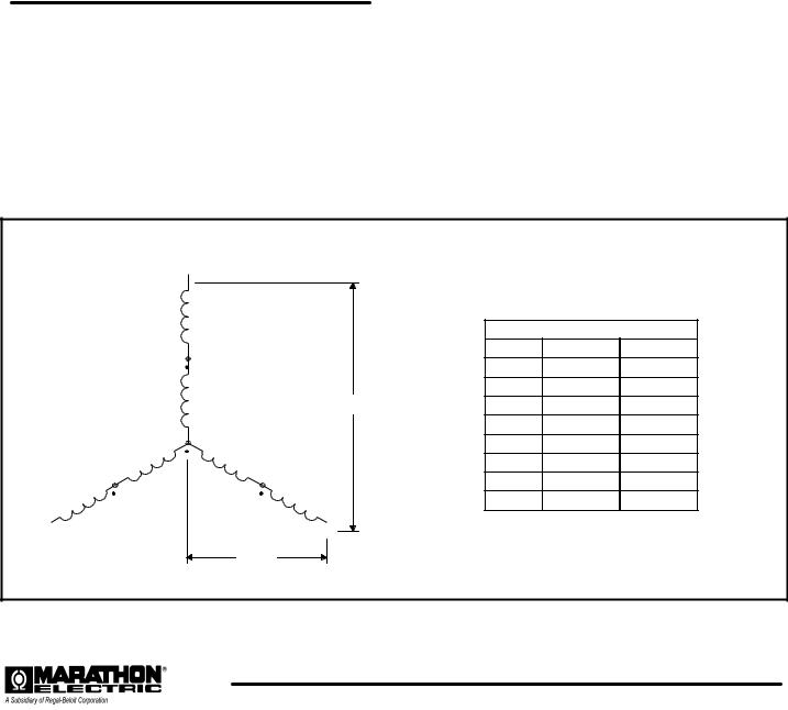
Refer to the connection diagram supplied with the generator and / or the proper diagrams shown in this manual. Install all inter-component and external wiring in accordance with national and local electrical codes. The neutral in the following connection diagrams shown below may be either grounded (earthed) or left above ground potential (floating). See national and local codes and / or the system distribution wiring schematic diagram for the proper connection of the neutral.
The following connection diagrams are shown for twelve lead generators. Ten lead generators have the same terminal designations except for leads T10, T11, and T12. These three leads are internally connected inside the generator and brought out as a single lead (T0). Ten lead generators can only be connected in a wye configuration
|
HIGH (SERIES) WYE CONNECTION |
|
|
||
|
L1 |
|
|
|
|
|
T1 |
|
|
|
|
|
|
VOLTAGE (HIGH WYE) |
|||
|
T4 |
Hz |
L-L |
L-N |
|
|
60 |
480 |
277 |
||
|
|
||||
|
T7 |
L - L |
460 |
266 |
|
|
|
440 |
254 |
||
|
T10 |
|
416 |
240 |
|
|
|
380 |
219 |
||
|
T12 |
50 |
416 |
240 |
|
T9 |
T11 |
||||
|
400 |
231 |
|||
T6 |
T8 |
|
380 |
219 |
|
T |
|
||||
T |
|
|
|
||
3 |
5 |
|
|
|
|
L3 |
T2 |
L |
|
|
|
|
L - N |
2 |
|
|
|
|
|
|
|
||
6
 Loading...