

Page 1
SM32A
VR28-013
DC/DC Power Converter
Serial Numbers 1221 and later
INSTALLATION AND OPERATION MANUAL
REV 4.00 Aug 21, 2006
Northern Airborne Technology Ltd.
1925 Kirschner Road
Kelowna, BC, Canada.
V1Y 4N7
Telephone (250) 763-2232
Facsimile (250) 762-3374
Copyright 2006 by Northern Airborne Technology
CONFIDENTIAL AND PROPRIETARY TO NORTHERN AIRBORNE TECHNOLOGY LTD.
Page 2

Page 3
SM32A Rev 4.00 VR28-013 DC/DC Power Converter Manual
Periodically NAT will release manual amendments. In order to maintain the most
accurate and up to date manual these amendments should be carried out immediately
upon receipt and recorded on the following amendment record.
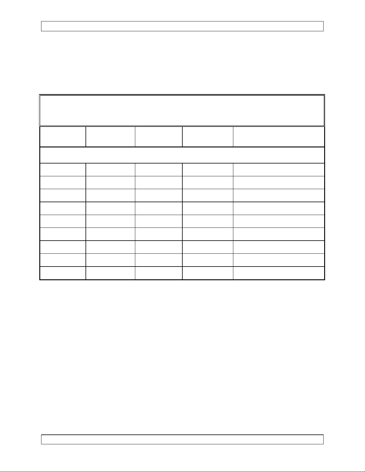
AMENDMENT RECORD
Amendment
Number
Note: Revision 4.00 is the first public release of this document
Amendment
Date
Section(s)
Changed
Date
Entered
Entered By
Insert any Amendment Instruction sheets after this page.
Aug 21, 2006 Page ii
ENG-FORM: 820-0110.DOT
CONFIDENTIAL AND PROPRIETARY TO NORTHERN AIRBORNE TECHNOLOGY LTD.
Page 4

Page 5

SM32A Rev 4.00 VR28-013 DC/DC Power Converter Manual
Table of Contents
Section Title Page
1 Description
1.1 Introduction 1-1
1.2 Purpose of Equipment 1-1
1.3 Features 1-1
1.4 Specifications 1-1
1.4.1 Electrical Specifications 1-1
1.4.2 Physical Specifications 1-2
1.4.3 Miscellaneous Specifications 1-3
1.4.4 Environmental Specifications 1-3
2 Installation
2.1 Introduction 2-1
2.2 Unpacking and Inspection 2-1
2.2.1 Warranty 2-1
2.3 Installation Procedures 2-1
2.3.1 Warnings 2-1
2.3.2 Cautions 2-1
2.3.3 Cabling and Wiring 2-2
2.3.4 Post-Installation Checks 2-2
2.4 Continued Airworthiness 2-3
2.5 Accessories Required But Not Supplied 2-3
2.6 Installation Drawings 2-3
3 Operation
3.1 Introduction 3-1
3.2 General 3-1
3.3 Operation Specifics 3-1
Aug 21, 2006 Page iii
ENG-FORM: 820-0110.DOT
CONFIDENTIAL AND PROPRIETARY TO NORTHERN AIRBORNE TECHNOLOGY LTD.
Page 6

Page 7

SM32A Rev 4.00 VR28-013 DC/DC Power Converter Manual
Section 1 Description
1.1 Introduction
This manual contains information on the VR28-013 DC/DC Power Converter (serial
numbers 1221 and later). All derivative products will be covered by manual
supplements, which can be obtained from NAT as required.
Information in this section consists of purpose of equipment, features and specifications.
1.2 Purpose of Equipment
The VR28-013 is an efficient voltage converter designed to power non-aircraft radios or
equipment from a 28 Vdc aircraft power buss. It is a remote bulkhead mounted unit
designed to convert a nominal +28 Vdc input to a nominal +13 Vdc output at up to 6 Amps.
1.3 Features
The VR28-013 uses the same switched-mode power supply (SMPS) circuitry utilized by
NT-series radios to provide constant output power without excessive heat generation.
The unit has remote on/off switching.
An output power LED is provided to give a visual indication that the unit is operating.
Power In, Power Out, and Ground pins are grouped together and internally connected
for installation versatility.
The unit has over-voltage and reverse-voltage protection to ensure operation in severe
aircraft environments.
1.4 Specifications
1.4.1 Electrical Specifications
Power Supply: Switched-mode regulated power supply with input reverse-polarity, over-
current, over-voltage, and output short-circuit protection.
Operating Voltages
Nominal +28.0 Vdc
Minimum +22.0 Vdc
Maximum +30.3 Vdc
Emergency +18.0 Vdc
Aug 21, 2006 Page 1-1
ENG-FORM: 800-0108.DOT
CONFIDENTIAL AND PROPRIETARY TO NORTHERN AIRBORNE TECHNOLOGY LTD.
Page 8

VR28-013 DC/DC Power Converter Manual SM32A Rev 4.00
Current Consumption
Standby 0.03 A nom. (Off)
No Load 0.1 A nom. (@ I
Low Current Load 0.5 A nom. (@ I
0.8 A nom. (@ I
High Current Load 2.0 A nom. (@ I
4.0 A nom. (@ I
=0.0 A)
OUT
=0.6 A)
OUT
=1.2 A)
OUT
=3.0 A)
OUT
=6.0 A)
OUT
Power Output
Intermittent Operation +13.0 Vdc ±10%, 6.0 A max.
Continuous operation +13.0 Vdc ±10%, 20% duty cycle:
1 minute at I
4 minutes at I
=6.0 A,
OUT
OUT
=1.2 A
Efficiency 80% typical
Input Overcurrent Protection Internal Fuse, 7 A capacity
Input Signals
Power On/Off: Voltage: <1 Vdc (logic LO) for ON
Current: 15 mA nom., sink
Output Signals N/A
1.4.2 Physical Specifications
Height 1.85" (47.0 mm) max
Depth 5.32" (135.1 mm) max
Width 3.99" (101.3 mm) max
Weight 1.02 lbs (0.46 kg) max
Mounting Remote bulkhead mount with four 10-32 screws
Material/Finish:
Chassis and cover Brushed aluminum with chromate conversion finish
Heatsink Aluminum extrusion with clear anodized finish
Connectors: J3 Male 15 pin D-submin connector with jackposts
Page 1-2 Aug 21, 2006
ENG-FORM: 800-0108.DOT
CONFIDENTIAL AND PROPRIETARY TO NORTHERN AIRBORNE TECHNOLOGY LTD.
Page 9

SM32A Rev 4.00 VR28-013 DC/DC Power Converter Manual
1.4.3 Miscellaneous Specifications
External Input Overcurrent Protection: 5 A External Circuit Breaker recommended
External Output Overcurrent Protection: 7.5 A External Fuse recommended
1.4.4 Environmental Specifications
Temperature:
Operating -20° C. to +55° C
Survival -55° C. to + 85° C
Vibration/Shock DO-160C Cat B/M/N
Altitude 35,000 feet
Humidity 95% Non-condensing
End of section 1
Aug 21, 2006 Page 1-3
ENG-FORM: 800-0108.DOT
CONFIDENTIAL AND PROPRIETARY TO NORTHERN AIRBORNE TECHNOLOGY LTD.
Page 10

Page 11

SM32A Rev 4.00 VR28-013 DC/DC Power Converter Manual
Section 2 Installation
2.1 Introduction
Information in this section consists of: unpacking and inspection procedures, installation
procedures, post-installation checks, and installation drawings.
2.2 Unpacking and Inspection
Unpack the equipment carefully and locate the warranty card. Inspect the unit visually
for damage due to shipping and report all such claims immediately to the carrier
involved. Note that each unit should have the following:
- VR28-013 DC/DC Power Converter
- Warranty Card
- Release certification
Verify that all items are present before proceeding and report any shortage immediately
to your supplier.
2.2.1 Warranty
Complete the warranty card information and send it to NAT when the installation is
complete. If you fail to complete the warranty card, the warranty will be activated on
date of shipment from NAT.
Note: An appropriately rated facility, e.g. Certified Aircraft Repair Station, must install this
equipment in accordance with applicable regulations. NAT Ltd’s warranty is not
valid unless the equipment is installed by an authorized NAT Dealer. Failure to
follow any of the installation instructions, or installation by a non-certified individual
or agency will void the warranty, and may result in a non-airworthy installation.
2.3 Installation Procedures
2.3.1 Warnings
Do not bundle any lines from this unit with transmitter coax lines. Do not bundle any
logic or audio lines with this unit. Do not position this unit next to any device
with audio
interfaces, or significant audio interference will result.
2.3.2 Cautions
In all installations, use shielded cable exactly as shown, and ground as indicated.
Significant problems may result from not following these guidelines.
Aug 21, 2006 Page 2-1
ENG-FORM: 805-0109.DOT
CONFIDENTIAL AND PROPRIETARY TO NORTHERN AIRBORNE TECHNOLOGY LTD.
Page 12

Page 13

VR28-013 DC/DC Power Converter Manual SM32A Rev 4.00
2.3.3 Cabling and Wiring
All wiring should be at least 22 AWG, except power and ground lines, which should be
at least 18 AWG. Ensure that all ground connections are clean and well secured.
All unshielded wire shall be selected in accordance with AC43.13-1B Change 1,
Paragraphs 11-76 through 11-78. Wire types should be to MIL-W-22759 as specified in
AC43.13-1B Change 1, Paragraphs 11-85, 11-86, and listed in Table 11-11. For
shielded wire applications, use Tefzel MIL-C-27500 shielded wire with solder sleeves
(for shield terminations) to make the most compact and easily terminated interconnect.
Follow the wiring diagrams in Section 2.6 as required.
Allow 3 inches from the end of the wire to the shield termination to allow the hood to be
easily installed. Note that the hood is a ‘clamshell’ hood, and is installed after the wiring
is complete.
All wiring should be at least 22 AWG, except power and ground lines, which should be
at least 20 AWG. Ensure that all ground connections are clean and well secured.
2.3.4 Post-Installation Checks
If any preset requires adjustment, be sure this is carried out before the aircraft leaves,
and that the unit and its mating connector are secured before departure. Make all
required log book entries, electrical load, weight and balance amendments and other
paperwork as required by your local regulatory agency.
2.3.4.1 Voltage/resistance checks
Do not attach the VR28-013 until the following conditions are met.
Check the following:
a) Check harness pins <1>, <2> and <9> for +28 Vdc relative to ground.
b) Ensure +13 Vdc lines pins <6>, <7> and <14> are not shorted to ground.
c) Check P101, pins <4> <11> and <12> for continuity to ground (less than 0.5 Ω).
2.3.4.2 Power On checks
Power up the aircraft's system with the VR28-013 installed, and confirm that the unit is
operating properly and the Power Output LED is on.
Double-check that the mounting and connector hardware is tightened securely.
Upon satisfactory completion of all performance checks, make the required log
entries and complete the necessary Regulatory Agency paperwork before
releasing the aircraft for service.
Page 2-2 Aug 21, 2006
ENG-FORM: 805-0109.DOT
CONFIDENTIAL AND PROPRIETARY TO NORTHERN AIRBORNE TECHNOLOGY LTD.
Page 14

Page 15

SM32A Rev 4.00 VR28-013 DC/DC Power Converter Manual
2.4 Continued Airworthiness
Maintenance of the VR28-013 is ‘on condition’ only. Periodic maintenance of this
product is not required.
2.5 Accessories Required But Not Supplied
Installation kit p/n VR28-IKC (crimp) is required to complete the installation. The kit
consists of the following:
VR28-IKC 15-pin D-min Female Crimp Kit (NAT Part No. D15SL-IKC)
Quantity Description NAT Part #
1 D-min 15 Socket Housing 20-21-015
15 MS Crimp Socket 20-26-901
1* Jack Screw Set 20-27-002
1* Lock Clip Set 20-27-004
1 15 Pin Connector Hood 20-29-015
* Use as required.
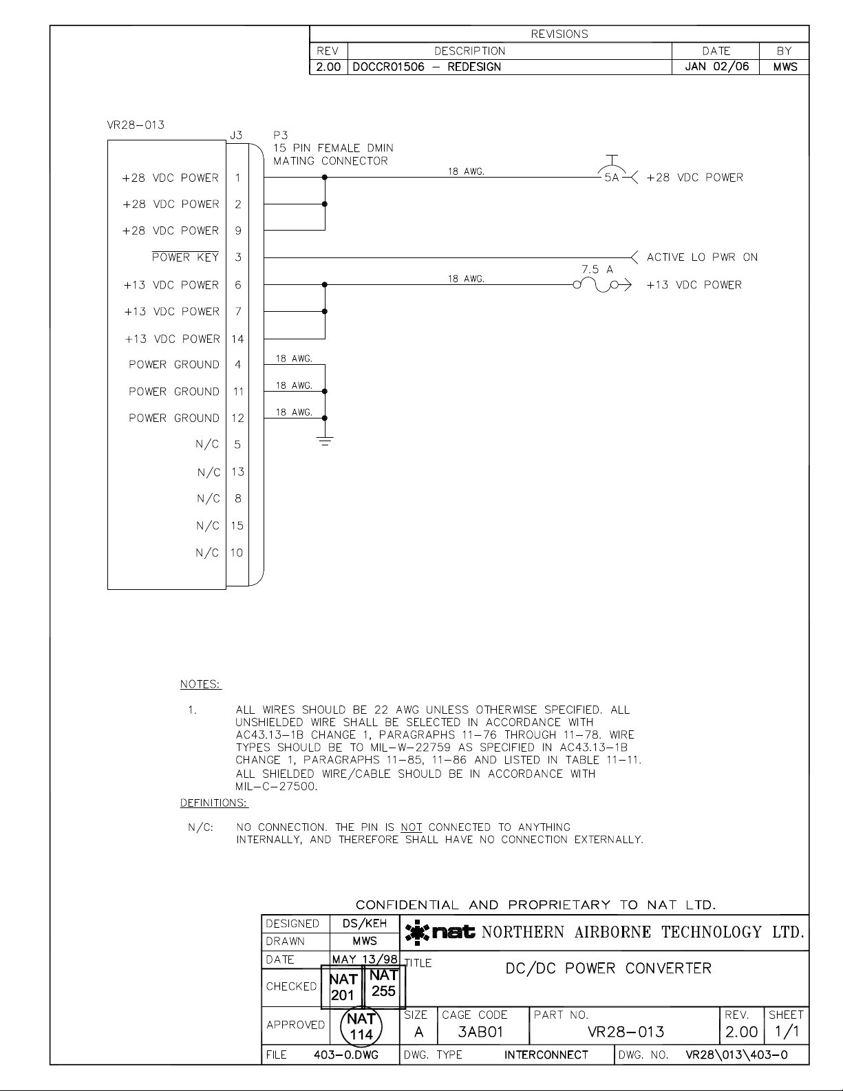
2.6 Installation Drawings
DRAWING REV. DESCRIPTION TYPE SERIAL #
VR28\013\403-0 2.00 DC/DC Power Converter Interconnect 1221 and up
VR28\013\405-0 2.00 DC/DC Power Converter Connector Map 1221 and up
VR28\013\922-0 2.00 DC/DC Power Converter Mech. Installation 1221 and up
Section 2 ends after these Drawings
Aug 21, 2006 Page 2-3
ENG-FORM: 805-0109.DOT
CONFIDENTIAL AND PROPRIETARY TO NORTHERN AIRBORNE TECHNOLOGY LTD.
Page 16

Page 17
Page 18

Page 19

Page 20

Page 21

Page 22

Page 23

SM32A Rev 4.00 VR28-013 DC/DC Power Converter Manual
Section 3 Operation
3.1 Introduction
Information in this section consists of the functional and operational procedures for the
VR28-013 DC/DC Power Converter.
3.2 General
When the Power Key line (J2 - pin 3) is grounded, the unit will turn on and the preset
output voltage will be generated.
An external LED located near the connector illuminates green to indicate that the
circuitry is working and that output power is being generated.
3.3 Operation Specifics
The VR28-013 has no user operational aspects.
End of section 3
Aug 21, 2006 Page 3-1
ENG-FORM: 806-0106.DOT
CONFIDENTIAL AND PROPRIETARY TO NORTHERN AIRBORNE TECHNOLOGY LTD.
Page 24

 Loading...