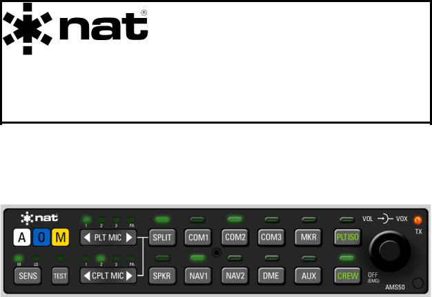
Northern Airborne Technology AMS50 User Manual

SM50
AMS50-000
Stereo Audio Panel with Marker
INSTALLATION AND OPERATION MANUAL
REV 4.00 November 12, 2003
Northern Airborne Technology Ltd.
1925 Kirschner Road
Kelowna BC, Canada
V1Y 4N7
Telephone (250) 763-2232
Facsimile (250) 762-3374
Copyright 2003 by Northern Airborne Technology
CONFIDENTIAL AND PROPRIETARY TO NORTHERN AIRBORNE TECHNOLOGY LTD.

SM50 Rev 4.00 |
AMS50-000 Stereo Audio Panel with Marker Manual |
Periodically NAT will release manual amendments. In order to maintain the most accurate and up to date manual these amendments should be carried out immediately upon receipt and recorded on the following amendment record.
AMENDMENT RECORD
Amendment |
Amendment |
Section(s) |
Date |
Entered By |
Number |
Date |
Changed |
Entered |
|
1 |
Jan 18\05 |
2 |
|
|
|
|
|
|
|
2 |
Mar 20\06 |
2, 3 |
|
|
|
|
|
|
|
|
|
|
|
|
|
|
|
|
|
|
|
|
|
|
|
|
|
|
|
|
|
|
|
|
|
|
|
|
|
|
|
|
|
|
|
|
|
|
|
Insert any Amendment Instruction sheets after this page.
Nov 12, 2003 |
Page ii |
ENG-FORM: 820-0109.DOT |
|
CONFIDENTIAL AND PROPRIETARY TO NORTHERN AIRBORNE TECHNOLOGY LTD.

INSTALL_OPS
MANUAL AMENDMENT
|
|
|
|
|
|
|
|
Manual: SM50 (AMS50) |
Amendment #: 2 |
||
Document # SM50\Install_Ops\809-0002 |
Amendment Date: Mar 20, 2006 |
||
|
|
|
|
The purpose of this amendment is to correct the PTT function description and change a connector reference.
Amendment Instructions:
1 |
Remove Pages |
Replace With Pages |
|
|
|
|
|
|
|
2-9 and 2-10 Rev 4.00 Amendment # 1 |
2-9 and 2-10 Rev 4.00 Amendment # 2 |
|
3-1 and 3-2 Rev 4.00 |
3-1 and 3-2 Rev 4.00 Amendment # 2 |
|
|
|
|
|
|
2Update the Amendment Record sheet at the front of the manual.
3Insert this page into the manual after the Amendment Record sheet (page ii).
Manual Amendment ends after the following amended pages
Amendment # 2 |
Mar 20, 2006 |
Page 1 |
ENG-FORM: 809-0109.DOT |
|
|
CONFIDENTIAL AND PROPRIETARY TO NORTHERN AIRBORNE TECHNOLOGY LTD.


INSTALL_OPS
MANUAL AMENDMENT
|
|
|
|
|
|
|
|
Manual: SM50 (AMS50) |
Amendment #: 1 |
||
Document # SM50\Install_Ops\809-0001 |
Amendment Date: Jan 18, 2005 |
||
|
|
|
|
The purpose of this amendment is to add the Environmental Qualification Form (521-0) to section 2.5 and to update section 2.3.3 Cable and Wiring statement paragraph 1.
1 |
Remove Pages |
Replace With Pages |
|
|
|
|
|
|
|
2-1, 2-2, 2-9 and 2-10 Rev 4.00 |
2-1, 2-2, 2-9 and 2-10 Amendment #1 Rev 4.00 |
2 |
|
|
|
|
|
|
|
|
Remove Drawings/Documents (Section 2) |
Replace or add Drawings/Documents (Section 2) |
|
|
|
|
|
|
|
|
- |
AMS50\000\521-0 Rev 1.00 |
|
|
|
|
|
|
Note: Ensure that all drawings are inserted in the order shown on the latest drawing lists.
3Update the Amendment Record sheet at the front of the manual.
4Insert this page into the manual after the Amendment Record sheet (page ii).
Manual Amendment ends after the following amended pages
Amendment #1 |
Jan 18, 2005 |
Page 1 |
ENG-FORM: 809-0109.DOT |
|
|
CONFIDENTIAL AND PROPRIETARY TO NORTHERN AIRBORNE TECHNOLOGY LTD.

|
SM50 Rev 4.00 |
AMS50-000 Stereo Audio Panel with Marker Manual |
||
|
|
|
|
|
|
|
Table of Contents |
|
|
|
Section |
Title |
Page |
|
|
|
|
|
|
|
1.0 |
Description |
|
|
1.1 |
Introduction |
1-1 |
|
|
1.2 |
Purpose of Equipment |
1-1 |
|
|
1.3 |
Features |
1-1 |
|
|
1.4 |
Specifications |
1-2 |
|
|
1.4.1 |
Electrical Specifications |
1-2 |
|
|
1.4.2 |
Physical Specifications |
1-4 |
|
|
1.4.3 |
Environmental Specifications |
1-4 |
|
|
1.4.4 |
Certification |
1-4 |
|
|
1.5 |
Unit Nomenclature |
1-5 |
|
|
1.5.1 |
Marker Beacon |
1-5 |
|
|
1.5.2 |
Special Features |
1-5 |
|
|
1.5.3 |
Cosmetic Differences |
1-5 |
|
|
|
2.0 |
Installation |
|
|
2.1 |
Introduction |
2-1 |
|
|
2.2 |
Unpacking and Inspection |
2-1 |
|
|
2.2.1 |
Warranty |
2-1 |
|
|
2.3 |
Installation Procedures |
2-1 |
|
|
2.3.1 |
Warnings |
2-1 |
|
|
2.3.2 |
Cautions |
2-2 |
|
|
2.3.3 |
Cabling and Wiring |
2-2 |
|
|
2.3.4 |
Accessories Supplied |
2-3 |
|
|
2.3.5 |
Mechanical Installation |
2-4 |
|
|
2.3.6 |
Installation Options and Features |
2-5 |
|
|
2.3.7 |
Adjustments |
2-7 |
|
|
2.3.8 |
Post-Installation Checks |
2-9 |
|
|
2.4 |
Continued Airworthiness |
2-10 |
|
|
2.5 |
Installation Drawings |
2-10 |
|
|
Nov 12, 2003 |
Page iii |
ENG-FORM: 820-0109.DOT |
|
CONFIDENTIAL AND PROPRIETARY TO NORTHERN AIRBORNE TECHNOLOGY LTD.
|
SM50 Rev 4.00 |
AMS50-000 Stereo Audio Panel with Marker Manual |
||
|
3.0 |
Operation |
|
|
3.1 |
Introduction |
3-1 |
|
|
3.2 |
Controls and Indicators |
3-1 |
|
|
3.2.1 |
Transmit Operation |
3-1 |
|
|
3.2.2 |
Receive Functions |
3-2 |
|
|
3.2.3 |
ICS Functions |
3-3 |
|
|
3.2.4 |
Speaker and Test Buttons |
3-4 |
|
|
3.2.5 |
ICS and VOX Volume Control |
3-5 |
|
|
3.2.6 |
Marker Beacon |
3-6 |
|
|
3.2.7 |
Automatic Fail-safe |
3-6 |
|
|
3.2.8 |
Optional Features |
3-7 |
|
|
3.3 |
Start-Up Selections |
3-7 |
|
|
Nov 12, 2003 |
Page iv |
ENG-FORM: 820-0109.DOT |
|
CONFIDENTIAL AND PROPRIETARY TO NORTHERN AIRBORNE TECHNOLOGY LTD.

SM50 Rev. 4.00 |
AMS50-000 Stereo Audio Panel Manual |
Section 1.0 Description
1.1Introduction
This manual contains information on the AMS50-000 Stereo Audio Panel.
Information in this section consists of purpose of equipment, features and specifications.
1.2Purpose of Equipment
The AMS50-000 is a full-function stereo audio panel with a six-place, voice-activated
(VOX) intercom and an optional built-in Marker Beacon receiver. The front panel controls feature clean responsive switching for crucial audio management. Transmitter and receiver selections are quick and precise using soft touch push-buttons. Positive feedback is provided in two formats: tactile and visual (colored LED's).
1.3Features
Radio functions include independently selectable transmit capability for Pilot and Co-pilot on 3 COM radios. Pilot’s transmit selection also has remote capability (yoke or cyclic).
Receive audio selections include: COM1, COM2, COM3, MKR, NAV1, NAV2, DME and AUX. COM3 is configurable at time of installation for use with an aviation phone.
The built-in six-place VOX intercom system with ALL, CREW, and PLT ISO modes, features NAT’s Active Noise Filtering (ANF ) system. This advanced technology filters out unwanted ambient noise entering the intercom channel, thus better isolating the human voice. Clear, clean intercom communications result in a safer and more comfortable flight.
Wind, engine and other fatigue noises are significantly reduced within the intercom system by utilizing independent microphone circuits. By ‘turning on’ only the active microphone, internal communications are quieter and less stressful.
Protection circuits help to prevent accidental damage from overvoltage and reverse voltage conditions.
Accommodation is provided for two (2) direct unswitched inputs for functions such as telephone ringer, Rad Alt, GPS alerts, and an Option Select input controls firmware related functions (i.e. Karaoke).
Automatic fail-safe operation is provided in the event of a power failure. The Pilot is routed directly to COM1 and the unswitched direct audio inputs. This mode can also be manually selected using the OFF (EMG) switch (see section 3.2.5.3 of this manual.)
Nov 12, 2003 |
Page 1-1 |
ENG-FORM: 800-0106.DOT |
|
CONFIDENTIAL AND PROPRIETARY TO NORTHERN AIRBORNE TECHNOLOGY LTD.

AMS50-000 Stereo Audio Panel Manual |
SM50 Rev. 4.00 |
1.4Specifications
1.4.1Electrical Specifications
Power Supply |
|
|
|
|
Input voltage: |
11-33 Vdc @ 3.0 A max. (one input for both) |
|
|
|
Note: For emergency voltages below 11 Vdc, the |
|
|
|
Manual Fail-safe mode must be used. |
|
|
Internal supply: |
± 8 Vdc for ICS and music to phones, |
|
|
|
+ 12 Vdc for speaker and front panel lighting |
|
|
|
+ 5 Vdc for logic circuitry |
|
|
Nominal Lighting Voltage: |
27.5 Vdc @ 10 mA max |
two separate inputs |
|
|
13.8 Vdc @ 10 mA max |
|
|
|
|
|
Input Signals |
|
|
|
|
Microphone: |
6 inputs, 250 mVrms into 150 Ω (Fixed) |
|
|
Receive Audio: |
3 COM inputs , 5 NAV inputs. (COM3 |
|
|
|
configurable for use with aviation phone). |
|
|
|
2.5 Vrms into 510 Ω (Fixed) |
|
|
RX detection: |
50 mVrms min |
|
|
Sidetone Level: |
2 mW (1 Vrms) min into 510 Ω |
|
|
Keylines: |
Two TX keys (Pilot and Co-pilot). |
|
|
Music input: |
Stereo input, switchable between portable |
|
|
|
cassette/CD player or rack mounted CD player. |
|
|
Portable Cassette or CD: |
400 mVrms (Nominal) into 610 Ω |
|
|
|
250 mVrms to 700 mVrms |
|
|
Rack mounted CD Player: |
2.5 Vrms (Nominal) into 3.5 kΩ |
|
|
|
1.0 Vrms to 4.5 Vrms |
|
Output Signals |
|
|
|
|
Headphones: |
6 stereo outputs, at full volume, > 70 mW into 300 Ω, |
|
|
|
< 10% THD each side. (> 100 mW into 150 Ω). |
|
|
ICS Volume Range: |
40 ± 5 dB |
|
|
Radio Audio Adjustments: |
Controlled at each radio source. |
|
|
Speaker: |
Adjustable: 0-7 W into 4 Ω @ 27.5 Vdc supply |
|
|
|
0-3.5 W into 4 Ω @ 13.8 Vdc supply |
|
|
COM MIC |
3 outputs @ 250 mVrms into 150 Ω each, |
|
|
|
controlled by either PLT or CPLT. |
|
|
PA MIC |
1 output @ 250 mVrms into 150 Ω, controlled |
|
|
|
by either PLT or CPLT. |
|
|
|
|
|
|
Page 1-2 |
|
Nov 12, 2003 |
|
ENG-FORM: 800-0106.DOT |
|
|
CONFIDENTIAL AND PROPRIETARY TO NORTHERN AIRBORNE TECHNOLOGY LTD.
SM50 Rev. 4.00 |
AMS50-000 Stereo Audio Panel Manual |
Performance/Function |
|
TSO-C50c |
RTCA DO-170 Class II |
Rated Output Power |
40 mW into 300 Ω (each phone channel) |
Rated Speaker Output Power |
7 W into 4 Ω (3.5 W into 8 Ω) |
|
2 W into 4 Ω @ 13.8 Vdc power |
Audio freq. response: |
|
Receive |
< 3 dB from 350 - 6000 Hz |
Intercom |
< 3 dB from 350 - 3000 Hz |
Music |
< 3 dB from 50 - 15000 Hz |
Speaker |
< 3 dB from 450 – 6000 Hz |
Distortion: |
< 10% at rated power |
Input - Input crosstalk: |
> 30 dB |
Input - Output crosstalk: |
> 50 dB |
Input - Mic crosstalk: |
< 1.0 mVrms |
Audio noise: |
< -50 dB |
Output Regulation: |
< 3 dB output power variance < 10% THD |
Audio Communication: |
Loud & Clear |
ICS Volume controls: |
40 ± 5 dB |
Receive Input impedance: |
510 Ω ± 5% |
Mic Input impedance: |
150 Ω ± 5% |
Music Input impedance: |
610 Ω ± 5% and 3.5 kΩ ± 10% |
Marker Beacon |
|
TSO-C35d |
Class A |
Receiver Frequency: |
75 MHz |
Sensitivity: |
|
Lo |
1000 µV |
Hi |
200 µV |
Selectivity: |
6 dB (min.) @ ± 10 kHz |
|
40 dB (max.) @ ± 200 kHz |
Input Impedance: |
50 Ω (ohm) |
Lamp Output: |
400 Hz Blue indicator marked ‘O’ (Outer) |
|
1300 Hz Amber indicator marked ‘M’ (Middle) |
|
3000 Hz White indicator marked ‘A’ (Airways) |
External lamps: |
Active Lo 125 mA max. sink current. |
|
|
Nov 12, 2003 |
Page 1-3 |
ENG-FORM: 800-0106.DOT |
|
CONFIDENTIAL AND PROPRIETARY TO NORTHERN AIRBORNE TECHNOLOGY LTD.

AMS50-000 Stereo Audio Panel Manual |
SM50 Rev. 4.00 |
Middle Marker sense: |
Active Hi (4.5 Vdc) during Middle Marker |
|
acquisition, for autopilot. |
Audio level: |
Phones audio level side adjustable: 0.5 - 2.5 Vrms. |
Distortion: |
<30% (Input signal from receiver threshold to 50 mV.) |
1.4.2Physical Specifications
Enclosure size behind panel: |
|
Height |
1.13” (28.7 mm) max. |
Length |
6.70” (170.2 mm) max. |
Width |
6.25” (158.8 mm) max. |
Weight |
2 lb. (909 g) |
Mounting |
Tray mount with center securing rod - 3/32” hex |
|
(Allen) key. |
Connectors |
44-pin card edge connectors. Crimp contacts |
|
#18-22 AWG and #22-26 AWG gold plating |
|
over nickel plate. |
Material/Finish |
|
Chassis & Cover |
Brushed aluminum with chromate conversion. |
Tray |
Stainless Steel |
1.4.3Environmental Specifications
Temperature: |
|
Operating |
-20°C to +55°C |
Survival |
-55°C to +85°C |
Altitude |
50,000 ft |
Humidity |
95% |
Shock, Crash Safety |
6g, 20g |
DO-138 |
[Z] |
RTCA DO-160D Env. Cat. [A1D1]-BAB[(SBM)(UF)]XXXXXXABABA[(TTX)]MXXXX.
1.4.4 |
Certification |
|
Audio Selector Panels and Amplifiers: |
RTCA DO-170, Class II |
|
|
|
RTCA DO-160D |
Airborne Radio Marker Receiver: |
RTCA DO-143, Class A |
|
|
|
RTCA DO-138, DO-160D |
Page 1-4 |
Nov 12, 2003 |
ENG-FORM: 800-0106.DOT |
|
CONFIDENTIAL AND PROPRIETARY TO NORTHERN AIRBORNE TECHNOLOGY LTD.

SM50 Rev. 4.00 |
AMS50-000 Stereo Audio Panel Manual |
1.5Unit Nomenclature
Variants of the AMS50 series Stereo Audio Panel will be covered by manual supplements to be inserted in Section 8 (Supplements) of this manual, and are identified as follows:
AMS50 - 000
Marker Beacon Capabilities |
Cosmetic Differences |
|
Special Features |
||
|
1.5.1Marker Beacon
The digit in the first position of the unit suffix indicates the Marker Beacon Capabilities.
AMS50 - 000
0 |
= |
Marker Beacon Capabilities |
1 |
= |
No Marker Beacon Capabilities |
1.5.2Special Features
The digit in the second position of the unit suffix indicates any special features installed.
AMS50 - 000
0 |
= |
No Special Features |
Other = |
Special Features (see relevant supplement for details.) |
|
1.5.3Cosmetic Differences
The digit in the third position of the unit suffix indicates Cosmetic Differences.
AMS50 - 000
0= Black faceplate with silver crown
1= Black faceplate with black crown
Other = Other cosmetic differences (see relevant supplement for details.)
End of section 1.0
Nov 12, 2003 |
Page 1-5 |
ENG-FORM: 800-0106.DOT |
|
CONFIDENTIAL AND PROPRIETARY TO NORTHERN AIRBORNE TECHNOLOGY LTD.
 Loading...