

Page 1
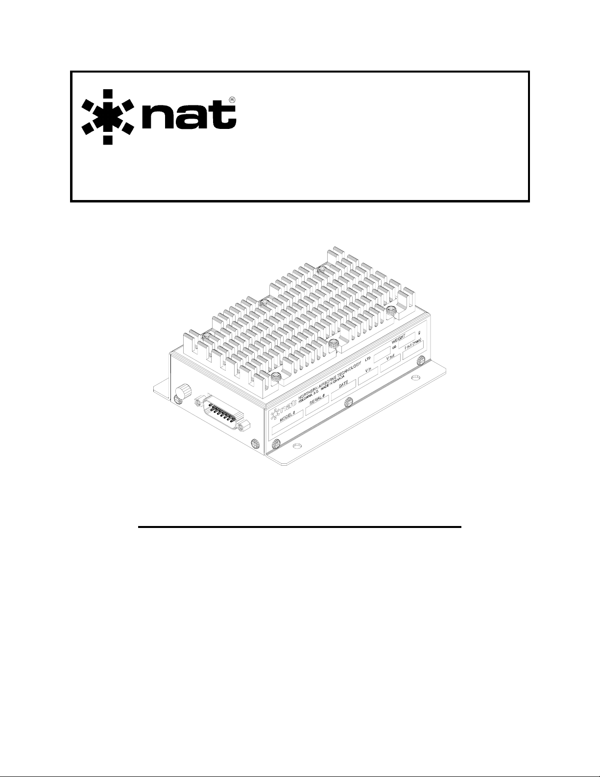
SM32
VR28-013
Voltage Regulator
Up to Serial Number 1220
INSTALLATION AND OPERATION MANUAL
REV 4.00 Nov 10, 2003
Northern Airborne Technology Ltd.
1925 Kirschner Road
Kelowna BC, Canada
V1Y 4N7
Telephone (250) 763-2232
Facsimile (250) 762-3374
Copyright 2003 by Northern Airborne Technology
Amendment # 1 Aug 17, 2006
Page 2

Page 3
SM32 Rev. 4.00 VR28-013 Voltage Regulator Manual
Performed at factory
Periodically NAT will release manual amendments. In order to maintain the most
accurate and up to date manual these amendments should be carried out immediately
upon receipt and recorded on the following amendment record.
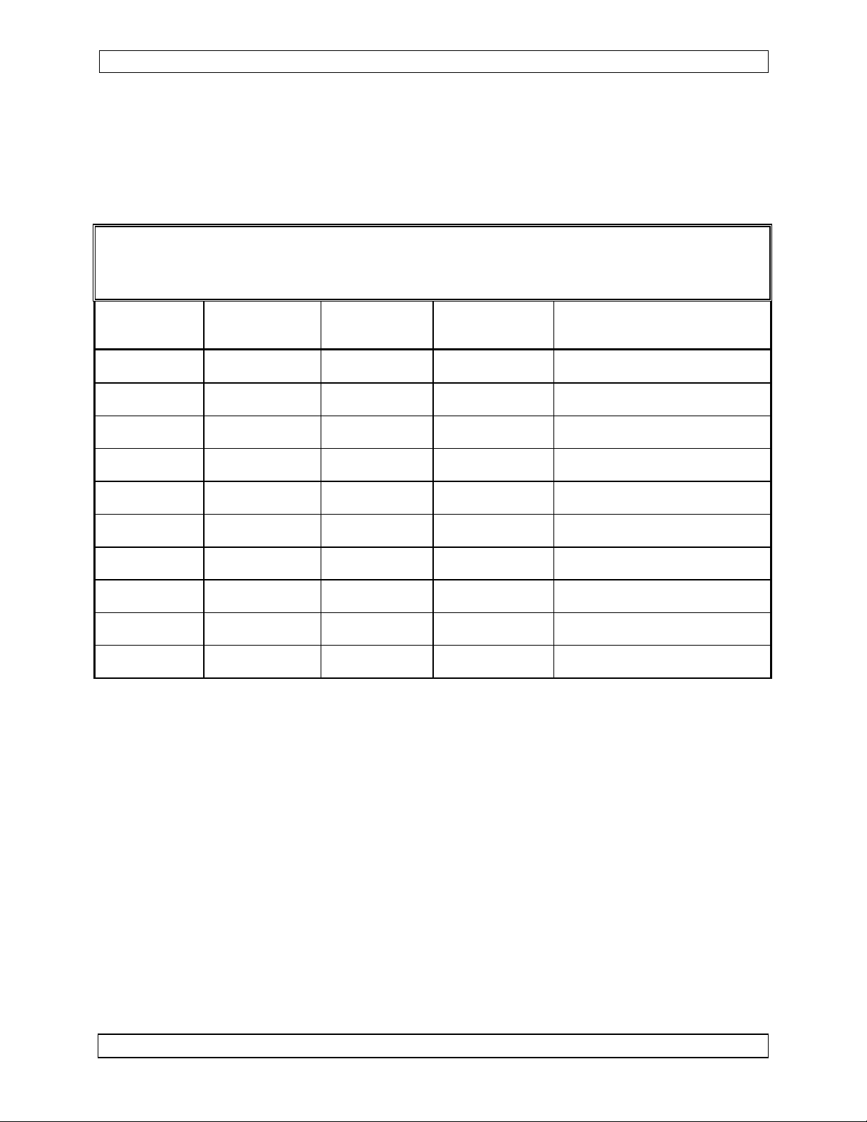
AMENDMENT RECORD
Amendment
Number
Amendment
Date
Section(s)
Changed
Date
Entered
Entered By
1 Aug 17/06 Title, i-iii
Insert any Amendment Instruction sheets after this page.
Nov 10, 2003 Page ii
ENG-FORM: 820-0109.DOT Amendment # 1 Aug 17, 2006
CONFIDENTIAL AND PROPRIETARY TO NORTHERN AIRBORNE TECHNOLOGY LTD.
Page 4

Page 5
INSTALL_OPS
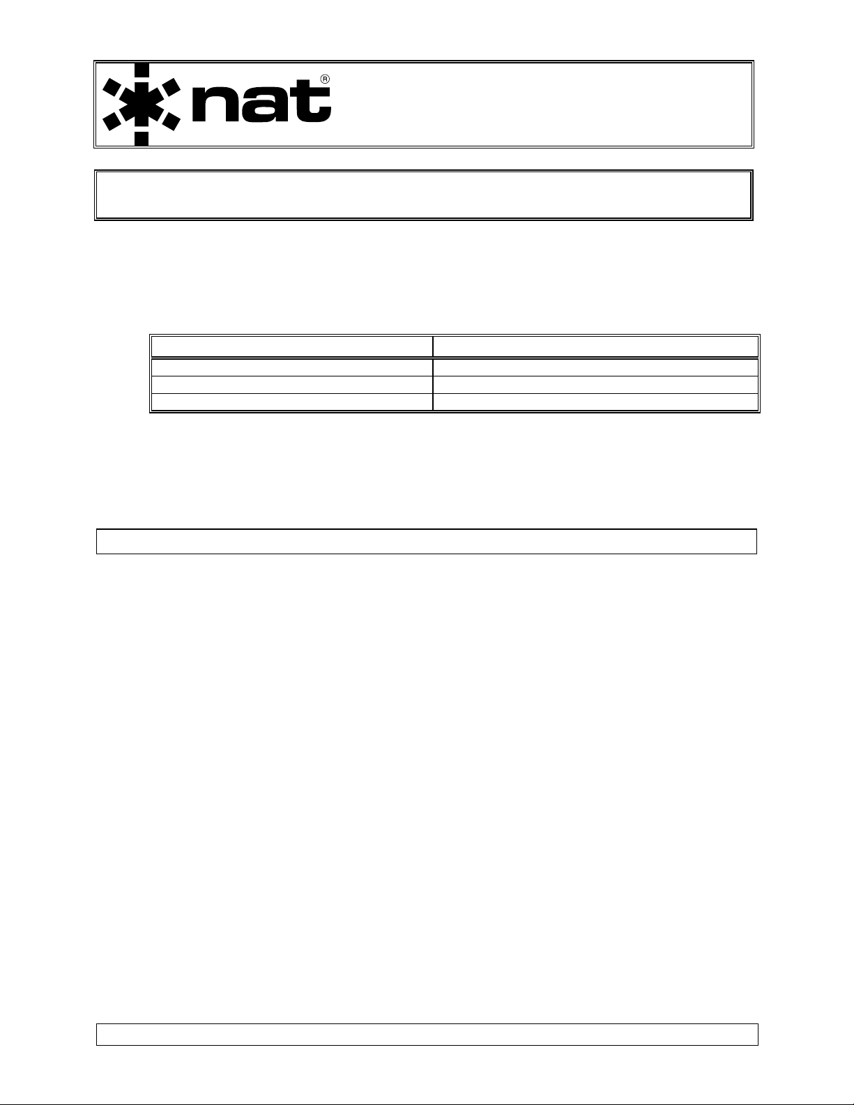
MANUAL AMENDMENT
Manual: SM32 (VR28-013 up to s/n 1220) Amendment #: 1
Document # SM32\Install_Ops\809-0001 Amendment Date: Aug 24, 2006
The purpose of this amendment is to insert serial number effectivity for the first version
of the VR28-013 Voltage Regulator manual SM32.
Amendment Instructions:
1
Title section (Pages i-iii) Rev 4.00 Title section (Pages i-iii) Rev 4.00 Amendment # 1
2 Update the Amendment Record sheet at the front of the manual.
3 Insert this page into the manual after the Amendment Record sheet (page ii).
Manual Amendment ends after the following amended pages
Remove Pages Replace With Pages
Amendment # 1 Aug 17, 2006 Page 1
ENG-FORM: 809-0109.DOT
CONFIDENTIAL AND PROPRIETARY TO NORTHERN AIRBORNE TECHNOLOGY LTD.
Page 6

Page 7

SM32 Rev. 4.00 VR28-013 Voltage Regulator Manual
Table of Contents
Section Title Page
1.0 Description
1.1 Introduction 1-1
1.2 Purpose of Equipment 1-1
1.3 Design Features 1-1
1.4 Specifications 1-1
1.4.1 Electrical Specifications 1-1
1.4.2 Physical Specifications 1-2
1.4.3 Environmental Specifications 1-2
2.0 Installation
2.1 Introduction 2-1
2.2 Unpacking and Inspection 2-1
2.3 Installation Procedures 2-1
2.3.1 Warnings 2-1
2.3.2 Cautions 2-1
2.3.3 Cabling and Wiring 2-1
2.3.4 Post-Installation Checks 2-2
2.4 Continued Airworthiness 2-2
2.5 Accessories Required But Not Supplied 2-2
2.6 Installation Drawings 2-3
3.0 Operation
3.1 Introduction 3-1
3.2 General 3-1
3.3 Operation Specifics 3-1
Nov 10, 2003 Page iii
ENG-FORM: 820-0109.DOT Amendment # 1 Aug 17, 2006
CONFIDENTIAL AND PROPRIETARY TO NORTHERN AIRBORNE TECHNOLOGY LTD.
Page 8

Page 9

SM32 Rev. 4.00 VR28-013 Voltage Regulator Manual
Section 1.0 Description
1.1 Introduction
The VR28-013 is a bulkhead mounted Voltage Regulator. Its adjustable output is
normally set to +13.0 Vdc with a maximum current of 5.5 Amps.
Note: Although only one model is currently available, a major revision was
implemented for serial numbers 1033 and following. The information contained
in this manual pertains to both revisions except where noted.
1.2 Purpose of Equipment
The VR28-013 is specifically designed to provide a method for installing +12 or +14 Vdc
equipment into an aircraft that has only +28 Vdc available.
1.3 Design Features
The VR28-013 uses the same switched mode power supply (SMPS) circuitry utilized by
NT series radios to provide constant output power without excessive heat generation.
The unit has remote on/off switching.
An output power LED is provided to give a visual indication that the unit is operating.
Power In, Power Out, and Ground pins are grouped together and internally connected
for installation versatility.
The unit has over-voltage and reverse-voltage protection to ensure operation in severe
aircraft environments.
1.4 Specifications
1.4.1 Electrical Specifications
Input Power: 24.8 to 29 Vdc.
Supply Current: 3.2 Amps at maximum load.
Output Power: Adjustable from +7 to +14 Vdc.
Output Current: 5.5 Amps (maximum) at 13.0 Vdc.
Nov 10, 2003 Page 1-1
ENG-FORM: 800-0106.DOT
CONFIDENTIAL AND PROPRIETARY TO NORTHERN AIRBORNE TECHNOLOGY LTD.
Page 10

SM32 Rev. 4.00 VR28-013 Voltage Regulator Manual
Indicators: Green Power Input monitor (internal).
Red Power Output monitor (external).
Keying: Power Key active low.
1.4.2 Physical Specifications
Height 1.77" (44.9 mm) max
Length 5.21" (132.3 mm) including connector
Width 3.95" (100.3 mm) including flanges
Weight 14.0 oz (400 g)
Mounting Remote bulkhead mount with four 10-32 screws
Material/Finish Chassis and cover are 5052-H32 brushed
aluminum with chromate conversion finish.
Heatsink is clear anodized aluminum.
Connectors Male 15 pin D-submin connector with jackposts
1.4.3 Environmental Specifications
Temperature:
Operating -20° C. to +55° C.
Survival -55° C. to + 85° C.
Vibration/Shock DO-160C Cat B/M/N
Altitude 35,000 feet.
Humidity 95% Non-condensing.
End of section 1.0
Page 1-2 Nov 10, 2003
ENG-FORM: 800-0106.DOT
CONFIDENTIAL AND PROPRIETARY TO NORTHERN AIRBORNE TECHNOLOGY LTD.
Page 11

SM32 Rev. 4.00 VR28-013 Voltage Regulator Manual
Section 2.0 Installation
2.1 Introduction
Information in this section consists of: unpacking and inspection procedures, installation
procedures, post-installation checks, and installation drawings.
2.2 Unpacking and Inspection
Unpack the equipment carefully and locate the warranty card. Inspect the unit visually
for damage due to shipping and report all such claims immediately to the carrier
involved. Note that each unit should have the following:
- VR28-013 Voltage Regulator
- Warranty Card
- Release certification
Verify that all items are present before proceeding and report any shortage immediately
to your supplier.
Complete the warranty card information and send it to NAT when the installation is
complete. If you fail to complete the warranty card, the warranty will be activated on
date of shipment from NAT.
2.3 Installation Procedures
2.3.1 Warnings
Do not bundle any lines from this unit with transmitter coax lines. Do not bundle any
logic or audio lines with this unit. Do not position this unit next to any device
with audio
interfaces, or significant audio interference will result.
2.3.2 Cautions
In all installations, use shielded cable exactly as shown, and ground as indicated.
Significant problems may result from not following these guidelines.
2.3.3 Cabling and Wiring
All wiring should be at least 22 AWG, except power and ground lines, which should be
at least 18 AWG. Ensure that all ground connections are clean and well secured.
Nov 10, 2003 Page 2-1
ENG-FORM: 805-0105.DOT
CONFIDENTIAL AND PROPRIETARY TO NORTHERN AIRBORNE TECHNOLOGY LTD.
Page 12

VR28-013 Voltage Regulator Manual SM32 Rev. 4.00
2.3.4 Post-Installation Checks
2.3.4.1 Voltage/resistance checks
Do not attach the VR28 until the following conditions are met.
Check the following:
a) Check harness pins <1> <2> and <9> for +28 Vdc relative to ground.
b) Check pins <4> <11> and <12> for continuity to ground (less than 0.5 Ω).
c) Ensure +13 Vdc lines pins <6>, <7> and <14> are not shorted to ground.
2.3.4.2 Power On checks
Power up the aircraft's system with the VR28 installed, and confirm that the unit is
operating properly and the Power Output LED is on.
Double check that the mounting and connector hardware is tightened securely.
Upon satisfactory completion of all performance checks, make the required log
entries and complete the necessary MOT/FAA paperwork before releasing the
aircraft for service.
2.4 Continued Airworthiness
Maintenance of the VR28 is ‘on condition’ only. Periodic maintenance of this product is
not required.
2.5 Accessories Required But Not Supplied
Installation kit p/n VR28-IKC (crimp) or VR28-IKS (solder) is required to complete the
installation. They consist of the following:
VR28-IKC 15-pin D-min Female Crimp Kit (NAT Part No. D15SL-IKC)
Quantity Description NAT Part #
1 D-min 15 Socket Housing 20-21-015
15 MS Crimp Socket 20-26-901
1* Jack Screw Set 20-27-002
1* Lock Clip Set 20-27-004
1 15 Pin Connector Hood 20-29-015
* Use as required.
Page 2-2 Nov 10, 2003
ENG-FORM: 805-0105.DOT
CONFIDENTIAL AND PROPRIETARY TO NORTHERN AIRBORNE TECHNOLOGY LTD.
Page 13

SM32 Rev. 4.00 VR28-013 Voltage Regulator Manual
VR28-IKS 15-pin D-min Female Solder Kit (NAT Part No. D15SL-IKS)
Quantity Description NAT Part #
1 D-min 15 Socket Solder Cup 20-20-015
1* Jack Screw Set 20-27-002
1* Lock Clip Set 20-27-004
1 15 Pin Connector Hood 20-29-015
* Use as required.
2.6 Installation Drawings
DRAWING REV. DESCRIPTION TYPE SERIAL #
VR28\013\403-0 1.00 Voltage Regulator Interconnect All
VR28\013\405-0 1.00 Voltage Regulator Connector Map All
VR28\013\922-0 1.00 Voltage Regulator Mech. Installation 1033 – 1041
VR28\013\922-0 1.10 Voltage Regulator Mech. Installation 1042 - 1064
VR28\013\922-0 1.20 Voltage Regulator Mech. Installation 1065 and up
Section 2.0 ends after these Drawings
Nov 10, 2003 Page 2-3
ENG-FORM: 805-0105.DOT
CONFIDENTIAL AND PROPRIETARY TO NORTHERN AIRBORNE TECHNOLOGY LTD.
Page 14

Page 15

Page 16

Page 17

Page 18

Page 19

Confidential and Proprietary to NAT
Page 20

Page 21

Page 22

Page 23

Page 24

Page 25

SM32 Rev. 4.00 VR28-013 Voltage Regulator Manual
Section 3.0 Operation
3.1 Introduction
Information in this section consists of the functional and operational procedures for the
VR28-013 Voltage Regulator.
3.2 General
When the Power Key line (J2 - pin 3) is grounded, the unit will turn on and the preset
output voltage will be generated.
An external LED located near the connector illuminates red to indicate that the circuitry
is working and that output power is being generated.
3.3 Operation Specifics
The VR28-013 has no user operational aspects.
End of section 3.0
Nov 10, 2003 Page 3-1
ENG-FORM: 806-0106.DOT
CONFIDENTIAL AND PROPRIETARY TO NORTHERN AIRBORNE TECHNOLOGY LTD.
Page 26

 Loading...