

Northern Airborne Technology THxxx User Manual
SM06
TAC/COM SERIES
Control Head
INSTALLATION AND OPERATION MANUAL
REV 4.10 January 4, 2006
Northern Airborne Technology Ltd.
1925 Kirschner Road
Kelowna, BC, Canada
V1Y 4N7
Telephone (250) 763-2232
Facsimile (250) 762-3374
Copyright 2006 by Northern Airborne Technology
CONFIDENTIAL AND PROPRIETARY TO NORTHERN AIRBORNE TECHNOLOGY LTD.

SM06 Rev. 4.10 Tac/Com Control Head Manual
Performed at factory
Periodically NAT will release manual amendments. In order to maintain the most
accurate and up to date manual these amendments should be carried out immediately
upon receipt and recorded on the following amendment record.
AMENDMENT RECORD
Amendment
Number
1 Oct 22/07 2
Amendment
Date
Section(s)
Changed
Date
Entered
Entered By
Insert any Amendment Instruction sheets after this page.
Jan 4, 2006 Page ii
ENG-FORM: 820-0110.DOT
CONFIDENTIAL AND PROPRIETARY TO NORTHERN AIRBORNE TECHNOLOGY LTD.

INSTALL_OPS
MANUAL AMENDMENT
Manual: SM06 (Tac/Com Series Control Head) Amendment #: 1
Document # SM06\Install_Ops\809-0001 Amendment Date: Oct 22, 2007
The purpose of this amendment is to update sections 2.3.3 and 2.3.4.
Amendment Instructions:
1
2-1, 2-2, 2-3, 2-4, 2-5 and 2-6 Rev. 4.10 2-1, 2-2, 2-3, 2-4, 2-5 and 2-6 Rev. 4.10
Note: Ensure that all drawings are inserted in the order shown on the latest drawing lists.
2 Update the Amendment Record sheet at the front of the manual.
3 Insert this page into the manual after the Amendment Record sheet (page ii).
Manual Amendment ends after the following amended pages
Remove Pages Replace With Pages
Amendment # 1
Amendment # 1 Oct 22, 2007 Page 1
ENG-FORM: 809-0109.DOT
CONFIDENTIAL AND PROPRIETARY TO NORTHERN AIRBORNE TECHNOLOGY LTD.


SM06 Rev. 4.10 Tac/Com Control Head Manual
Table of Contents
Section Title Page
1 Description
1.1 Introduction 1-1
1.2 General 1-1
1.2.1 Tac/Com Control Head Family 1-2
1.2.2 Accessories 1-3
1.3 Purpose of Equipment 1-5
1.3.1 Interface Considerations 1-6
1.3.2 Mixed Transceiver System 1-6
1.3.3 Radio Capability Increase With Tac/Com 1-7
1.3.4 Master/Slave Configuration 1-8
1.3.5 Frequency Data Considerations 1-9
1.4 Hardware Design Features & Considerations 1-10
1.4.1 General 1-10
1.4.2 Display Filtering/Lighting Options 1-10
1.5 Specifications 1-11
1.5.1 Electrical Specifications 1-11
1.5.2 Physical Specifications 1-12
1.5.3 Environmental Specifications 1-13
1.6 Unit Nomenclature 1-13
1.6.1 Series Designation 1-13
1.6.2 Number Of Radios 1-13
1.6.3 Display Type 1-14
1.6.4 Display Filter/Lighting Suffix Information 1-14
1.6.5 Interface-Specific Suffix Information 1-15
2 Installation
2.1 Introduction 2-1
2.2 Unpacking and Inspection 2-1
2.2.1 Warranty 2-1
2.3 Installation Procedures 2-1
2.3.1 Warnings 2-1
2.3.2 Cautions 2-2
2.3.3 Cabling and Wiring 2-2
2.3.4 Mechanical Mounting 2-3
2.3.5 Notes 2-3
2.4 Post Installation Checks 2-4
2.4.1 Voltage/Resistance Checks 2-4
2.4.2 Power On Checks 2-4
Jan 4, 2006 Page iii
ENG-FORM: 820-0110.DOT
CONFIDENTIAL AND PROPRIETARY TO NORTHERN AIRBORNE TECHNOLOGY LTD.


SM06 Rev. 4.10 Tac/Com Control Head Manual
Section Title Page
2.5 Troubleshooting 2-6
2.5.1 Weak Receive/Transmit, Intermittent Operation, Erratic Squelch 2-6
2.5.2 Strange Noises, No Receive Audio, Transmit Keying problems 2-6
2.5.3 Some Frequencies Can't be Edited 2-6
2.5.4 Display Brightness is Too Low, Can't Increase to Full Brightness 2-6
2.5.5 Amber (RX) Squelch light comes on, but no RX audio is heard. 2-7
2.6 Final Inspection 2-7
2.7 Continued Airworthiness 2-7
2.8 Installation Drawings 2-8
2.8.1 Outline drawings 2-8
2.8.2 System Connector (J-100) 2-8
3 Operation
3.1 Introduction 3-1
3.2 General 3-1
3.3 Initial Operation 3-2
3.3.1 Power-up Help 3-2
3.3.2 Initial Operating Display 3--2
3.4 Front Panel Controls 3-3
3.4.1 Radio Specific Controls 3-4
3.4.2 General Controls - NORMAL Operation 3-6
3.5 Editing 3-10
3.5.1 Channel Editing 3-11
3.5.2 Summary of Channel Editing 3-14
3.5.3 Summary of Channel Labels 3-15
3.5.4 Summary of Subaudible Tones 3-16
3.6 Status Line Editing 3-19
3.6.1 NEXT and SELECT Switch Use 3-20
3.6.2 Status Edit Features 3-21
3.7 Channel Display Summary 3-23
3.7.1 Display Switch Set to 'ID' 3-23
3.7.2 Display Switch Set to 'RX' 3-24
3.7.3 Display Switch Set to 'TX' 3-24
3.8 Changing Display Brightness 3-25
3.9 Scanning 3-25
3.9.1 Scan Modes 3-27
3.10 NAT NTX138 Wide-band/Narrow-band Operation 3-28
3.11 Master Edit Mode 3-29
3.11.1 Entering Master Edit Mode 3-29
3.11.2 How Data is Stored in the Control Head 3-30
3.11.3 Editing Considerations 3-30
3.12 Installation & Configuration Mode 3-31
3.12.1 Entering Configuration Mode 3-31
3.12.2 Configuration Option Table 3-32
Jan 4, 2006 Page iv
ENG-FORM: 820-0110.DOT
CONFIDENTIAL AND PROPRIETARY TO NORTHERN AIRBORNE TECHNOLOGY LTD.

SM06 Rev. 4.10 Tac/Com Control Head Manual
Section 1 Description
1.1 Introduction
This manual contains information on the NAT Tac/Com control heads. All derivative
products and interface cards will be covered by manual supplements, which can be
obtained from NAT as required.
Information in this section consists of purpose of equipment, features and specifications.
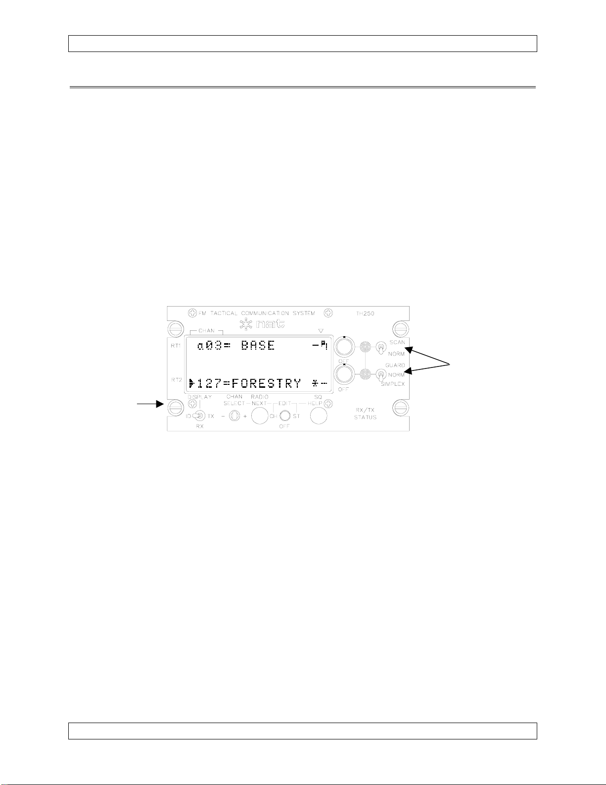
1.2 General
The Tac/Com control head provides exceptional flexibility and ease of operation while
using minimal panel space. In a Dzus panel height of only 4⅞ inches, up to four
transceiver systems can be controlled and accessed using a Tac/Com control head.
The controlled radio systems may be either NAT transceivers or combinations of
different manufacturer's transceivers.
Tac/Com controls are available in two basic families: Tac/Com I (both LED and LCD
displays), and Tac/Com II (LED only). Note that the Tac/Com I or ‘CH ‘ series control
heads have been discontinued since 1995. Tac/Com II control head variations include
2-, 3- or 4-transceiver support, master or slave versions and custom panel lighting, and
support expanded channel storage (up to 128 channels per radio), remote channel
selection, display auto-dimming, and full software configuration of the control head.
Features Tac/Com I Tac/Com II
Control/Display
Types
2 & 4 Radio LCD,
2 & 4 Radio LED
2, 3 & 4 Radio LED.
Channels/Radio 32 (NT) or 56 (non-scanning) 128 maximum.
Special
Features
HELP, Alphanumeric
Labelling of Channels
HELP, Alphanumeric
Labelling of Channels, Highspeed Scrolling, Remote
Radio/Channel Selection,
Auto Night Dimming.
Master/Slave Yes Yes
DTE12 Support No Yes
USFS Guard &
No Yes
Tone Capability
NT136-PAS
No Yes
Compatible
Jan 4, 2006 Page 1-1
ENG-FORM: 800-0108.DOT
CONFIDENTIAL AND PROPRIETARY TO NORTHERN AIRBORNE TECHNOLOGY LTD.
Tac/Com Control Head Manual SM06 Rev. 4.10
The Tac/Com control head carries its own operator's manual in internal software, and
can provide on-line help to the operator for all functions. An initial help mode at powerup can provide a complete tutorial of the control head and its operating and storage
functions, and pressing the HELP button during either EDIT operation brings up
context-sensitive help for the specific storage or data entry function being carried out.
This provides a simple way for new staff to train, as well as providing a private method
to refresh their knowledge of the system whenever they chose. The help information
‘manual’ can never be lost or misplaced because it forms part of the basic control head
itself.
Radio control functions and transceiver interfaces are determined by a combination of
Tac/Com control head software and internal radio-specific interface cards. To specify a
complete control head, you must select the basic size format and the internal interfaces.
The range of control heads is shown graphically in the Tac/Com control head family
drawing below.
1.2.1 Tac/Com Control Head Family
Each control head type can have user-specified interfaces installed as required. Control
heads with LCD displays are no longer available (available as Tac/Com I only). Current
models are available with LED displays (Tac/Com II).
Two-Radio Control Heads
Three-Radio Control Heads
Page 1-2 Jan 4, 2006
ENG-FORM: 800-0108.DOT
CONFIDENTIAL AND PROPRIETARY TO NORTHERN AIRBORNE TECHNOLOGY LTD.
SM06 Rev. 4.10 Tac/Com Control Head Manual
Four-Radio Control Heads
1.2.2 Accessories
The Tac/Com family encompasses numerous specialized accessories to extend system
capability, as well as transceivers and the control heads reviewed in this manual.
NAT transceiver capabilities are covered in separate manuals. For reference, the
additional system components include:
1.2.2.1 Remote Mount VHF FM Transceivers
*NT030A-xxx Low Band
*NT030B-xxx Low Band
*NT136-xxx High Band
*NT150-xxx High Band
NTX066-xxx Mid Band
NTX138-xxx High Band/Narrow Band Compatible, available with USFS
Custom Guard option
NTX138E-100 High Band/Direction Finding (DF) Capability/Enhanced
environmental specifications
1.2.2.2 Remote Mount UHF FM Transceivers
*NT403-xxx Low Band
*NT450-xxx High Band
*NT450x-xxx High Band
*NT806-000 800 MHz
NTX403-xxx Low/High Band
* No longer available as new products.
Jan 4, 2006 Page 1-3
ENG-FORM: 800-0108.DOT
CONFIDENTIAL AND PROPRIETARY TO NORTHERN AIRBORNE TECHNOLOGY LTD.

Tac/Com Control Head Manual SM06 Rev. 4.10
1.2.2.3 TE12/DTE12/DP12 DTMF Tone Generator/Keyboard Data Entry Unit
These devices can output DTMF signalling tones from either keyboard control or stored
sequences, and can serve as a direct keyboard data entry system for Tac/Com control
heads to change channels and frequencies. Consult NAT Ltd. for further information.
1.2.2.4 RA10 Remote Attenuator
This group of remote signal attenuators can be used to alter receive and transmit
performance and range under operator control. They allow compliance with restricted
transmit power regulations even when the radio itself cannot alter its transmit level.
They are used extensively in Europe for changing TX power to even lower levels than
the 1W output possible via Tac/Com transceivers directly, and to reduce RX
interference from closely spaced repeaters by reducing RX sensitivity.
1.2.2.5 Tactical Direction Finding (TDF) System
This 2-axis DF system allows both left-right and fore-aft sensing with a pictorial display.
This provides exceptional accuracy during search and rescue and remote tracking
operations, and also provides a positive indication of station passage (impossible with
single axis systems) to aid in exact target location.
1.2.2.6 CC250/450 Communications Controllers
The CC250/450 is a compact, easy to install communications controller. It is designed
to provide relay and/or simulcast operation for up to 4 transceivers. With these
functions, the aircraft can become an airborne repeater or a multi-frequency transmitting
platform. When used to its potential, the CC250/450 provides increased efficiency and
reduced workload for communication operations. Only the CC450-0V2 is currently in
production.
1.2.2.7 CTE12 Calquest Headset Adapter
The CTE12-100 Calquest Headset Adapter is designed to interface standard avionics
headsets to the Calquest Cabin Network Unit (CNU). The headset adapter provides a
DTMF keypad, status indicators, ring chime control, ring/in-use annunciator control and
VOX squelch capability. The headset adapter can interface directly to a headset or a
standard avionics audio panel.
1.2.2.8 UT12 Universal Tone Encoder/Decoder
The UT12-000 is capable of encoding and decoding 5-tone CCIR tone sequences and
DTMF tones. It is compatible with the NAT Tac/Com system, and when used in
conjunction with a TH-series Tac/Com control head provides broader and easier control
over tones. The control head or transceiver can select, enable, disable and display
tones by communicating with the UT12-000 through a serial port.
Page 1-4 Jan 4, 2006
ENG-FORM: 800-0108.DOT
CONFIDENTIAL AND PROPRIETARY TO NORTHERN AIRBORNE TECHNOLOGY LTD.
SM06 Rev. 4.10 Tac/Com Control Head Manual
1.3 Purpose of Equipment
The Tac/Com series of control heads provides a centralized location for tactical radio
control and channelling of up to four independent transceiver systems. Only the
Tac/Com II series will be considered; for further information, contact NAT Ltd.
Alphanumeric labeling of each radio channel is provided, as well as a display of receive
and transmit frequencies, to ease pilot identification of the selected channel on each
radio.
At the Tac/Com (master) control head, individual radio receive volume and radio power
on/off status can be controlled. Individual radio functions can also be set, such as
scanning, tones, simplex/duplex, TX power and others. Annunciation is provided for TX
and RX activity on a per transceiver basis, and the main display can be set to show the
channel name (alphabetic label), the receive frequency and tone data, or the transmit
frequency and tone data for all radios via the general control group.
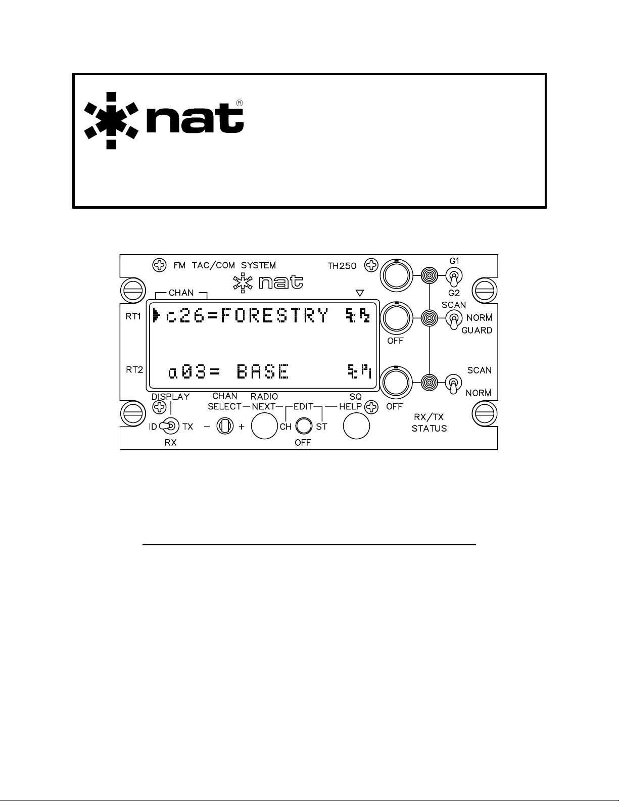
Radio
Controls
General
Controls
TH250 Control
(2 Radios, 256 Total Channels)
Within the control head, individual radio interface cards translate the control head
commands into suitable channelling data for each specific type of radio connected.
Software controlling these functions, as well as the built-in help screens for control head
operation, is located on the main control head CPU board and can be easily replaced to
upgrade or improve control head functions.
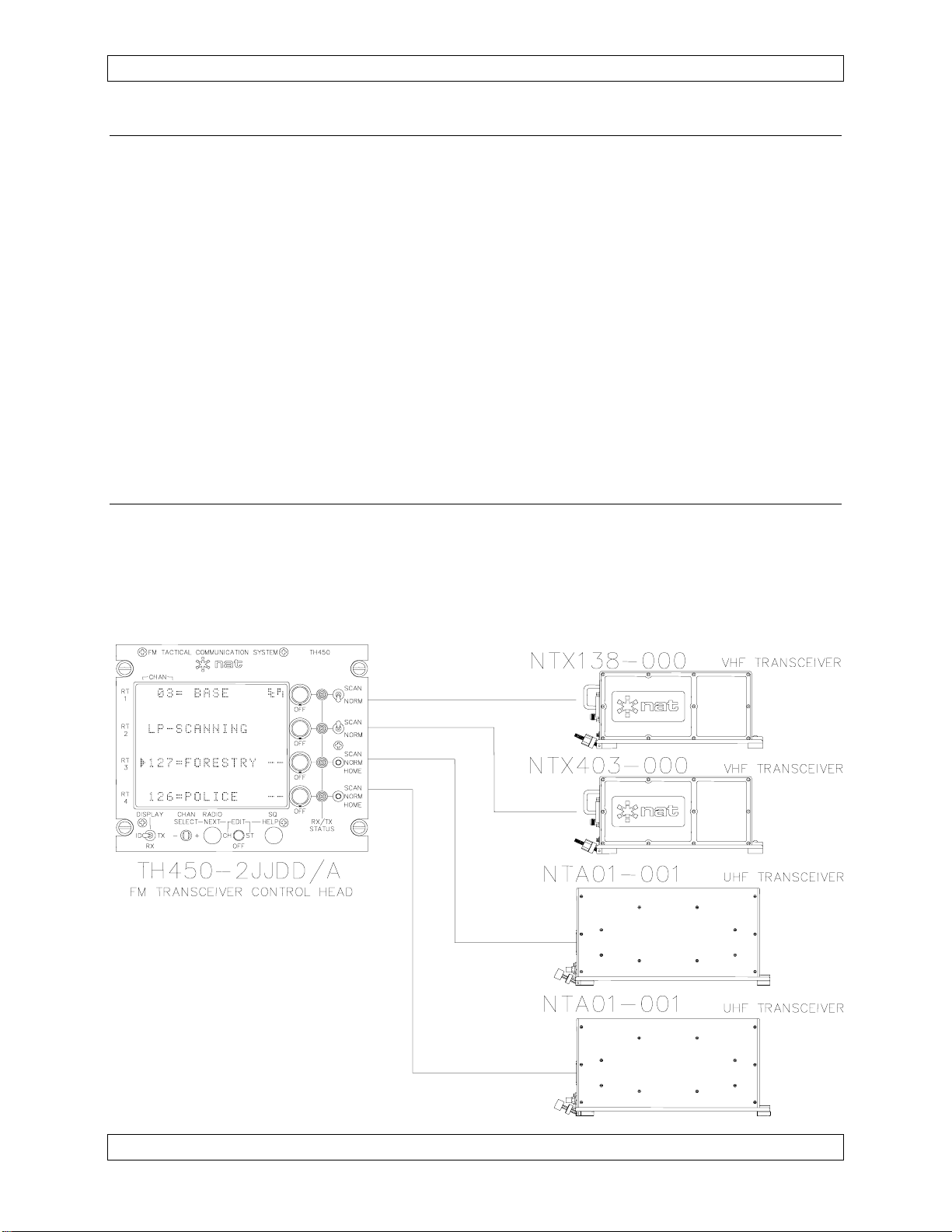
The software of the control head's computer can emulate many types of parallel tuned
radio controls and this allows the Tac/Com system to directly replace many existing
controls such as the C-960, C-961, C-962A, C-722A and C-1000. In addition, since the
Tac/Com control allows control of up to four simultaneous radio systems, the single
Tac/Com control can replace up to four individual controls, with a substantial reduction
in cost and panel space. The following diagram illustrates a system that shows this
multiple radio capability using NAT NT-series agile transceivers. Any combination of
radios could be used by installation of the appropriate interface cards within the control
head. In the example below, an accessory DTE12 is used for DTMF tone generation
and direct keyboard data input to the TH450.
Jan 4, 2006 Page 1-5
ENG-FORM: 800-0108.DOT
CONFIDENTIAL AND PROPRIETARY TO NORTHERN AIRBORNE TECHNOLOGY LTD.
Tac/Com Control Head Manual SM06 Rev. 4.10
1.3.1 Interface Considerations
Tac/Com offers direct plug compatibility for replacement of C-962/A and C-722/A control
heads (for use with the RT-9600 and RT-7200), including the second audio connector.
For USFS applications, Tac/Com provides some additional capability when used with the
RT-9600. Full guard receiver control can be brought out on the front panel, and the
limited tone capability of the RT-9600 (8 variable tones) can be replaced with the internal
tone capability of the Tac/Com ‘U’ interface, which provides all 32 standard CTCSS tones.
This interface remains plug-compatible, and also eliminates the awkward external tone
encoder required on USFS contracts. A USFS-compatible ‘V’ interface is provided for
use with NT150-050 guard-equipped radios, and the 'H' interface is designed for use with
the NTX138-050.
For use with existing Flexcomm installations, NAT provides an adapter cable (p/n
FC41-000 Flexcable) that permits direct connection from C-1000 airframe connectors
to the ‘F’ interface.
1.3.2 Mixed Transceiver System
The example shows a four radio Tac/Com control head running a mixed transceiver
group, to illustrate what is possible with the interface flexibility of Tac/Com internal
architecture. Transceivers may be a combination of fixed and agile radios, with and
without scanning, and can be from any of the supported interfaces that NAT provides.
See section 1.6.5 or consult Product Support at NAT for further information.
Page 1-6 Jan 4, 2006
ENG-FORM: 800-0108.DOT
CONFIDENTIAL AND PROPRIETARY TO NORTHERN AIRBORNE TECHNOLOGY LTD.

SM06 Rev. 4.10 Tac/Com Control Head Manual
1.3.3 Radio Capability Increase With Tac/Com
Wherever possible, NAT has increased the capability of other transceivers via the
Tac/Com control head, and those features are summarized below, compared to the
original controls:
Feature Tac/Com I Tac/Com II C1000 C962/722
Stored Channels
PL Tones*
No. of Transceivers
32/56 per Radio 128 per Radio 30 Total 15 Total
38 + 83 DPL
38 + 83 DPL
32 for W.E.D.
32
32 for W.E.D.
8
1 - 4 1 - 4 1 1
(simultaneous)
Alpha Labels
Remote Selection
Yes Yes No No
No Yes No No
(channels & radio)
Master/Slave
Yes Yes No No
(both active)
*NAT NT-series Radios have the capability shown. Tac/Com controls can provide 32
PL tones for Flexcomm. Tac/Com II can also provide an internal tone upgrade for the
RT-9600/7200 to provide all 32 standard EIA CTCSS tones (‘U’ interface).
PL = Private Line (also known as CTCSS)
DPL = Digital Private Line
W.E.D. = Wulfsberg Electronics Division
Note: Only NAT's own NT-series transceivers support all the features provided by
Tac/Com controls. Tac/Com controls cannot give a radio functions of which it is
inherently incapable. For example, older crystal-controlled Flitefone 40's do not
become agile radios when connected to a Tac/Com head, and Flexcomm radios
do not acquire high speed scanning or DPL capability.
Jan 4, 2006 Page 1-7
ENG-FORM: 800-0108.DOT
CONFIDENTIAL AND PROPRIETARY TO NORTHERN AIRBORNE TECHNOLOGY LTD.
Tac/Com Control Head Manual SM06 Rev. 4.10
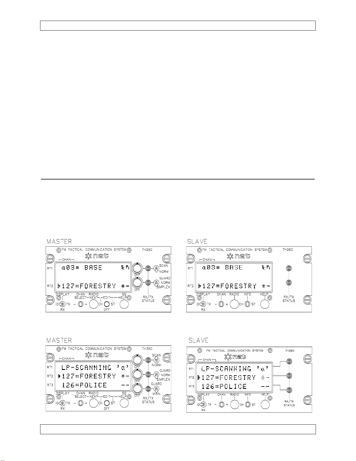
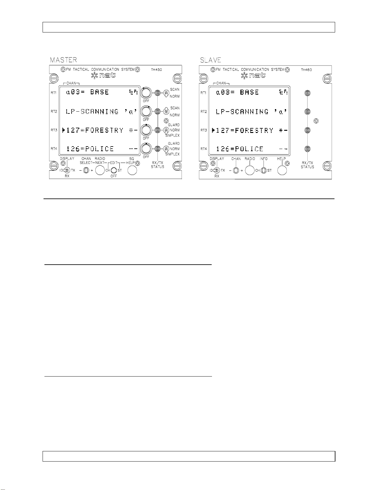
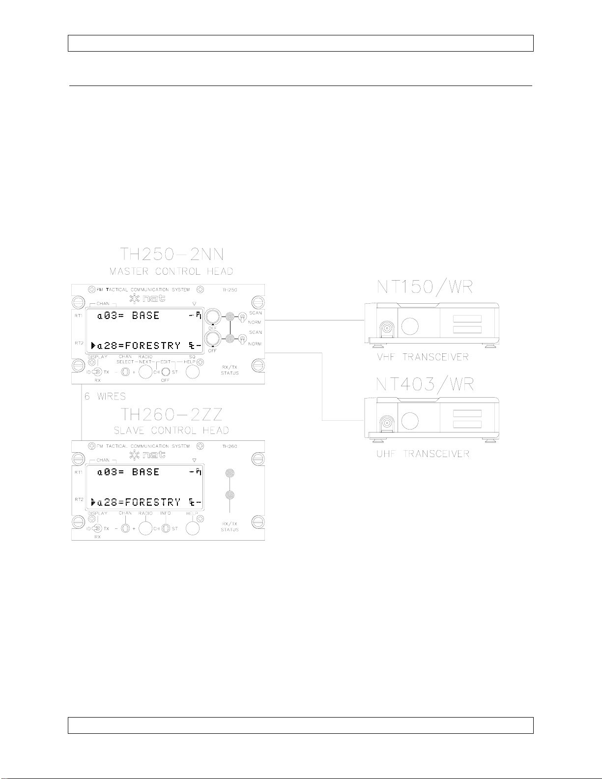
1.3.4 Master/Slave Configuration
One powerful configuration that NAT's Tac/Com controls support is the master/slave
configuration. In this configuration, two controls can be active at the same time (flight
crew and medical crew, for example), and both can select channels and radios. The
extraordinary aspect of this interface is the fact that this interconnect requires only 6
additional wires to give full support to both stations. Dual controls wired with other units
often require hundreds of wires, and still permit only a single control to be active at one
time.
A typical master/slave interconnect is illustrated below for clarification. Many
variations are possible, and the controls can be 2, 3 or 4 radio types, if required.
Page 1-8 Jan 4, 2006
ENG-FORM: 800-0108.DOT
CONFIDENTIAL AND PROPRIETARY TO NORTHERN AIRBORNE TECHNOLOGY LTD.

SM06 Rev. 4.10 Tac/Com Control Head Manual
1.3.5 Frequency Data Considerations
Tac/Com controls have an intelligent editor that prevents incorrect data entry when
programming frequencies for a given agile radio. VHF radios can receive only valid
VHF frequencies; UHF radios only UHF frequencies at the correct intervals, and so on.
This greatly eases operator use, and prevents many common pilot errors. The C-1000
permits many types of incorrect entries for radios because of its thumbwheel entry
system. This intelligent editor is especially useful when the Tac/Com control head has
been set to emulate a C-1000 (i.e., channel any Flexcomm radio), as it detects the
range of the radio as the data is being entered, and then restricts subsequent
information to correspond to the exact radio type.
Radios in each band-split have specific channel interval assignments (by law), and are
typically on 25 kHz, 15 kHz, 12.5 kHz, 6.25 kHz, 5 kHz or 2.5 kHz intervals. Which
multiples are possible depends on the design of the radio's synthesizer circuitry, history
and restrictions of the country of operation. Tac/Com automatically picks the correct
multiples for each radio type based on the stored installation data, and ensures that only
valid choices are possible for the operator.
If the operator enters invalid data via either external data entry or other procedure, the
control will advise of this error. User intervention is then required to correct the data
before proper radio operation can be achieved.
1.3.5.1 Frequency Programming
There are three ways to program channel data into a Tac/Com control head:
a) From the front panel controls (edit mode).
b) From a DTE12 Keyboard/Data Unit (edit mode, Tac/Com II only).
c) From a PC via NAT's data loading software & the system serial port.
1.3.5.2 Channel Selection
There are three ways to select a channel on a Tac/Com control head:
a) From the front panel controls.
b) From the remote select switches (Tac/Com II only).
c) From a DTE12 Keyboard/Data Unit (Tac/Com II only).
Jan 4, 2006 Page 1-9
ENG-FORM: 800-0108.DOT
CONFIDENTIAL AND PROPRIETARY TO NORTHERN AIRBORNE TECHNOLOGY LTD.

Tac/Com Control Head Manual SM06 Rev. 4.10
1.4 Hardware Design Features & Considerations
1.4.1 General
The Dzus mounted Tac/Com control heads use extremely high quality components,
including sealed gold contact switches, gold contact connectors and fully masked,
conformal-coated FR4 flame retardant circuit boards. Each unit is fully temperature
cycled, life-tested, and then supported with a solid one-year warranty and extensive
field support to ensure the best possible customer satisfaction.
A wide range energy conversion power supply is used in the control head, allowing
operation from 16-33 Vdc, for nominal 28 Vdc systems. Panel lighting must be adjusted
to suit the specific application, and is normally supplied as natural colouration 28 Vdc
incandescent lighting. Options include blue/white or NVG lighting available in +5, +14
or +28 operating voltages.
For ease of service, integrated circuits are socketed where possible, allowing fast return
to service of failed control heads and quicker bench troubleshooting. Control head
software is easily updated for improved features or expanded capability by an internal
EPROM exchange. Internal interface cards are plug-in modules to facilitate quick
service exchange or upgrade.
Wherever possible, fully plug-compatible interconnects are provided for existing systems
replaced by Tac/Com controls, making retrofits and test flights both easy to accomplish
and inexpensive. Where it is not possible to directly accomplish this within the control
head itself, an adapter cable or plug replacement on an existing cable is used.
1.4.2 Display Filtering/Lighting Options
Current LED displays used in Tac/Com II control heads are green (first generation
Tac/Com I controls used a yellow display), with fully formed 5x7-pixel alphanumeric
characters. They have a large character height of 5 mm/0.2" and a very wide viewing
angle (>150 degrees) that provides good readability from virtually all cabin mounting
locations, including centre consoles such as in the Bell 412/212.
Several display filter/panel lighting options are provided with LED controls to give the
best visual presentation in different ambient lighting conditions. ‘Filter’ refers to the
DISPLAY colour and appearance and ‘Panel Lighting’ refers to the panel legend back
lighting colour & voltage.
See Section 1.6 Unit Nomenclature for complete option list details.
The backlighting for the control head (which includes the LCD display) can be run from a
dimmer separate from other cockpit controls if more adjustment over the LCD back lighting is
desired. This will permit both backlighting and contrast to be adjusted for the best presentation.
The LED display automatically dims (on current production units) to 50% intensity when voltage
is detected on the control head light bus. The LED display is adjustable in 7 steps via the
SELECT (+/-) switch, when the Bright +/Dim - screen is displayed.
Page 1-10 Jan 4, 2006
ENG-FORM: 800-0108.DOT
CONFIDENTIAL AND PROPRIETARY TO NORTHERN AIRBORNE TECHNOLOGY LTD.

SM06 Rev. 4.10 Tac/Com Control Head Manual
1.5 Specifications
1.5.1 Electrical Specifications
Input Power: 16-33 Vdc.
Current: 0.25 A/LED Control 250 Series
0.35 A/LED Control 350 Series
0.45 A/LED Control 450 Series
0.15 A/LCD Control 400 Series
+0.075 A/Interface Card Installed (for all types)
+0.250 A/28 Vdc for panel lighting
Values above are maximum, display set to full intensity.
Panel Indicators: Two-colour LED indicates: TX - Green
RX (SQ) - Orange
One LED per radio, except when the interface
supports separate guard controls (‘U’, ‘V’, etc.), in
which case a second LED is provided for the guard
receiver.
Channel Storage: CH-series (Tac/Com I) 32/56 Channels per radio
TH series (Tac/Com II) 128 Channels per radio
Data Interface: Programming via standard RS-232 from a PC (NAT
software), or front panel for all functions.
Scanning: NT -series transceivers: 90 channels/second/radio.
NTX -series transceivers: 10-20 channels/second/radio.
Modes are LIST, PRIORITY, LIST + PRIORITY.
Priority monitoring is 3 times/second for 10-15 ms sample.
Radio will re-channel to the priority channel if traffic is
detected, and returns to the monitor channel after a 2
second latency.
All CTCSS tones or DPL codes are inactive during
scanning (due to lock delay).
Other scanning parameters depend on the radio type.
Jan 4, 2006 Page 1-11
ENG-FORM: 800-0108.DOT
CONFIDENTIAL AND PROPRIETARY TO NORTHERN AIRBORNE TECHNOLOGY LTD.

Tac/Com Control Head Manual SM06 Rev. 4.10
1.5.2 Physical Specifications
Height
Tac/Com Series Rail Height Required
250/260 and 350/360 3.00”
450A 3.75”
450B and 460B 3.375”
450/460 4.875”
Length 6.27 inches (159.3 mm) excluding connector
Width 5.8 inches (146.1 mm)
Weight 2.2 to 2.9 lbs (1 kg to 1.3 kg) depending on model
Mounting Horizontal through-panel Dzus mount.
Fits standard opening (5" clearance/5.75" panel width)
Requires 3" of rail height (450 series require 4.875")
Front Panel Controls: Radio Volume/Power ON-OFF
One or two radio-specific controls
Display Contrast (LCD)
Display Mode (ID/RX/TX)
Channel/Select (+/-)
Radio/Next
Edit Switch (Channel-Off-Status)
Squelch/Help
Internal Controls: Agile Channel Defeat/Enable (on interface cards)
Lamp Dimmer Voltage (Panel Overlay)
Squelch, Tone & Level Preset where applicable
Tac/Com I Only, pre-s/n 1129:
NAT R/T Band Select
RT-9600/7200 Mode Select
Flexcomm Band Select
Overall form factor matches C-722A/C-962A/C-1000
QA/Manufacturing Processes: TC AWM PART 561
MIL-STD-2000 (MU) Assembly
ISO9001-1994
Page 1-12 Jan 4, 2006
ENG-FORM: 800-0108.DOT
CONFIDENTIAL AND PROPRIETARY TO NORTHERN AIRBORNE TECHNOLOGY LTD.
SM06 Rev. 4.10 Tac/Com Control Head Manual
1.5.3 Environmental Specifications
Altitude: Pressurized alt. equivalent to 15,000'
Unpressurized alt. equivalent to 35,000'
Temperature: -20º C to +60º C Operating
-55º C to +85º C Survival
Humidity: 90% @ +60º C
Vibration: DO-160 category K/P/S, console or panel mounting in
both helicopters or fixed-wing. All Dzus fasteners
MUST be secured.
1.6 Unit Nomenclature
Tac/Com control heads are identified by two groups of numbers. The first defines the
general capability of the control head in terms of the total number of radios controlled
and type of display, and the second specifically defines the display filter and backlight
type, as well as the radio types supported. Each section of the part number defines part
of the control head capability.
General Capability Specific Interfaces
TH450 - 2NNFE
Display Filter Information
1.6.1 Series Designation
TH450 - 2NNFE
CH = Tac/Com I Series Controls
TH = Tac/Com II Series Controls Above example: Tac/Com II
1.6.2 Number Of Radios
TH250 - 2NN
2 = Two Radio Control
3 = Three Radio Control
4 = Four Radio Control Above example: 2 Radio
Jan 4, 2006 Page 1-13
ENG-FORM: 800-0108.DOT
CONFIDENTIAL AND PROPRIETARY TO NORTHERN AIRBORNE TECHNOLOGY LTD.

Tac/Com Control Head Manual SM06 Rev. 4.10
1.6.3 Display Type
TH450 - 2FFNN
00 = LCD Display, Master (Discontinued)
10 = LCD Display, Slave (Discontinued)
50 = LED Display, Master
60 = LED Display, Slave Above example: LED Master
1.6.4 Display Filter/Lighting Suffix Information
TH260 - 2ZZ
0 = Yellow/Green LED Filter, or Clear LCD Filter, Natural 28 Vdc lighting.
(LCD Standard)
1 = Dark Green LED Filter, NVG-friendly LED 28 Vdc lighting
2 = Dark Green LED Filter, Natural 28 Vdc lighting. (LED Standard)
3 = Yellow/Green LED Filter w/Z-cloth, Natural 28 Vdc lighting
4 = Dark Green LED Filter, Natural 5 Vdc lighting
5 = Dark Green LED Filter, NVG-friendly LED 5 Vdc lighting
6 = Dark Green LED Filter, Blue/White 28 Vdc lighting
7 = Circular Polarized glass, daylight, Natural 28 Vdc lighting
8 = Circular Polarized glass, daylight, Blue/White 5 Vdc lighting
9 = Deep Red Filter with Red LED Displays, Natural 28 Vdc lighting
10 = Yellow/Green with Amber LED Displays, Natural 28 Vdc lighting
11 = Circular Polarized glass, daylight, NVG-friendly LED 5 Vdc lighting
12 = Circular Polarized glass, daylight, NVG-friendly LED 28 Vdc lighting
13 = Circular Polarized glass, Natural 5 Vdc lighting
14 = Dark Green LED Filter, Blue/White 5 Vdc lighting
15 = Circular Polarized glass, daylight, Blue/White 28 Vdc lighting
16 = Circular Polarized glass, daylight, NVIS B Compliant 28 Vdc lighting
17 = Circular Polarized glass, daylight, NVIS B Compliant 5 Vdc lighting
Page 1-14 Jan 4, 2006
ENG-FORM: 800-0108.DOT
CONFIDENTIAL AND PROPRIETARY TO NORTHERN AIRBORNE TECHNOLOGY LTD.
SM06 Rev. 4.10 Tac/Com Control Head Manual
1.6.5 Interface-Specific Suffix Information
The position of the digit in the code reflects the position of the card in the control. The
code position from left to right equals the relevant card position from top to bottom.
TH450 - 2NNNE
A = ARINC 2 of 5 Comm M = Midland Syn-Tech I
B = Blank (No Controls) N = NAT NT-Series
C = Flitefone 40 O = Not Assigned
D = Motorola Astro/XTL Series P = RT9600/7200 Single Connector
D1 = Motorola Astro/XTL with zone function Q = RT9600 with Tones, No Guard
E = NT Slot. Controls only. No Card R = RT9600/7200 Plug Compatible
F = Flexcomm S = Motorola URC-200
G = Flex Slot. Controls only. No Card T = NAT NT-Series with Transcrypt
H = NTX Series with USFS Guard U = RT9600 with USFS Guard & Internal
I = Not Assigned 32 Tones
J = NAT Tac/Com NTX Series V = NAT NT-Series with USFS Guard
J1 = Chelton 805-1, 905-2, 915-1 W = Not Assigned
K = Midland Syn-Tech XTR X = Not Assigned
L = Motorola Spectra Y = Serial I/O Expansion Port
L1 = Motorola Spectra with zone function Z = General Slave Interface
Above example: 3 NAT & 1 Empty (Empty in bottom slot)
Earlier Tac/Com I controls had a different numbering scheme, using only a three
character suffix. If you need to convert an older number to a new one, contact NAT
for details, or consult revision 1.xx of this manual.
End of section 1
Jan 4, 2006 Page 1-15
ENG-FORM: 800-0108.DOT
CONFIDENTIAL AND PROPRIETARY TO NORTHERN AIRBORNE TECHNOLOGY LTD.


SM06 Rev. 4.10 Tac/Com Control Head Manual
Section 2 Installation
2.1 Introduction
Information in this section consists of: unpacking and inspection procedures, installation
procedures, post-installation checks, and installation drawings.
2.2 Unpacking and Inspection
Unpack the equipment carefully and locate the warranty card. Inspect the unit visually
for damage due to shipping and report all such claims immediately to the carrier
involved. Note that each unit should have the following:
Verify that all items are present before proceeding and report any shortage immediately
to your supplier.
2.2.1 Warranty
- Tac/Com Control Head
- Warranty Card
- Operator’s Manual
- Release certification
Complete the warranty card information and send it to NAT when the installation is
complete. If you fail to complete the warranty card, the warranty will be activated on
date of shipment from NAT.
Note: An appropriately rated facility, e.g. Certified Aircraft Repair Station, must install this
equipment in accordance with applicable regulations. NAT Ltd’s warranty is not
valid unless the equipment is installed by an authorized NAT Dealer. Failure to
follow any of the installation instructions, or installation by a non-certified individual
or agency will void the warranty, and may result in a non-airworthy installation.
2.3 Installation Procedures
2.3.1 Warnings
Do not bundle any lines from this unit with transmitter coax lines. Do not bundle any
lines from this unit with 400 Hz synchro wiring, or AC power lines. Failure to observe
these limitations may result in incorrect or intermittent operation, or severe audio
interference on received and transmitted signals.
In all installations, use shielded cable exactly as shown, and ground as indicated.
Significant noise problems and/or improper operation may result from not following
these guidelines.
Jan 4, 2006 Page 2-1
ENG-FORM: 805-0108.DOT Amendment # 1 Oct 22, 2007
CONFIDENTIAL AND PROPRIETARY TO NORTHERN AIRBORNE TECHNOLOGY LTD.

Tac/Com Control Head Manual SM06 Rev. 4.10
2.3.2 Cautions
All audio installations can be severely degraded by incorrect wiring and shielding, and
may result in much higher cross-talk, hum, and ground-loop interference. This should be
considered when installing audio wiring to and from the specific radio. Both the audio Hi
and Lo wires must be connected from the radios (audio outputs are floating transformer
windings on NT-series radios), and should be grounded only at the audio panel via the
audio common.
If multiple transceivers are installed, it is very beneficial to use tri-axial cable for the
antenna feedlines, with the outer shield grounded at the radio end only. This added
electro-static shielding greatly reduces cable coupling, and eliminates many types of
interference in the final installation. Observe proper antenna spacing and good routing
practice for all RF lines to avoid cross-talk, squelch interference, and phantom sidetone
problems.
2.3.3 Cabling and Wiring
All unshielded wire shall be selected in accordance with the original aircraft
manufacturer’s maintenance instructions or AC43.13-1B Change 1, Paragraphs 11-76
through 11-78. Wire types should be to MIL-W-22759 as specified in AC43.13-1B
Change 1, Paragraphs 11-85, 11-86, and listed in Table 11-11. For shielded wire
applications, use Tefzel MIL-C-27500 shielded wire with solder sleeves (for shield
terminations) to make the most compact and easily terminated interconnect. Follow the
wiring diagrams in Section 2.9 as required.
Installation cabling must allow the unit to be easily withdrawn for disconnection, switch
and pot settings (internal), and removal. Ensure an adequate service loop is allowed in
the routing of the cable. This can become a serious problem if the unit is installed with
the cables so short that the unit cannot be removed without disassembly of the
mounting console. At least 1 foot (30 cm) of free cable is recommended.
Allow 3 inches (8 cm) from the end of the wire to the shield termination to allow the
hood to be easily installed. Note that the hoods supplied by NAT in installation kits are
'clamshell' hoods, and are installed after the wiring is completed.
Generally, all wiring should be at least 22 AWG, except power and ground connections,
which should be 20 AWG - check the appropriate Interconnect drawing for the unit
under consideration. Ensure that the ground connection is clean and well secured. To
prevent inadvertent system failure, power to this system must be supplied from a
separate breaker or fuse, and not bundled to any other source. A 1A breaker is
suggested (28 Vdc source).
Notes: 1. The case is grounded electrically and should be attached to a grounded
surface for correct RFI shielding. A pin is provided for grounding the case,
and this must be connected via its own wire to a suitable ground, not
jumpered to the power ground wire connection.
Page 2-2 Jan 4, 2006
ENG-FORM: 805-0108.DOT Amendment # 1 Oct 22, 2007
CONFIDENTIAL AND PROPRIETARY TO NORTHERN AIRBORNE TECHNOLOGY LTD.
SM06 Rev. 4.10 Tac/Com Control Head Manual
2. The interface cards for the RT9600 and RT7200 have different locks from
those on the original harness. The tight packaging on the Tac/Com control
head does not allow spring locks to be used. The harness locks must be
changed to jackscrews to match the Tac/Com connectors before flight.
New locking hardware is furnished with the control head when these cards
are installed.
2.3.4 Mechanical Mounting
Installation should be in accordance with the aircraft manufacturer’s instructions for
continued airworthiness or AC 43.13-1B Change 1, chapter 7, sections 2 to 7 and AC
43.13-2A chapter 2.
Mounting is accomplished in a standard Dzus rack or rail assembly with a clearance
opening of 5", and full width dimension of 5.75". The rail height required for mounting
the various control heads is shown below.
Tac/Com Series Rail Height Required
250/260 and 350/360
450A
450B and 460B
450/460
3.00"
3.75"
3.375"
4.875"
Be sure that adequate rear cable clearance is allowed when planning console
installations. Refer to the aircraft structural repair manual and maintenance manual for
instructions and information pertinent to this installation.
2.3.5 Notes
2.3.5.1 Control Head System Connector
The J100 System Connector Power/Lights/Ground connections must be provided for
operation of the overall system, in addition to the basic interface card-to-radio
connections. For specific RT9600/7200 radios, see the relevant Interface Card
supplement (SM06\PQRU\810-0) for an alternative method for providing these
connections to the control head.
Pins 7, 10 and 22 are serial data control lines that may be brought out to a connector for
serial loading of the control by a PC. This allows easy large scale data changes without
removing the control head from the aircraft. NAT provides a special software package
for this function. This port may also be used for Master/Slave operation or the DTE12
DTMF/Keyboard Data Unit.
2.3.5.2 Additional Mounting Considerations
LED display units come in several different display filter styles (see Section 1.6), and
the panel location and filter type should be matched for the best performance. LED
Jan 4, 2006 Page 2-3
ENG-FORM: 805-0108.DOT Amendment # 1 Oct 22, 2007
CONFIDENTIAL AND PROPRIETARY TO NORTHERN AIRBORNE TECHNOLOGY LTD.

Tac/Com Control Head Manual SM06 Rev. 4.10
displays offer very wide viewing angles, and are suitable for centre console mounting
and locations not in the pilot's direct field of vision.
2.4 Post Installation Checks
Before the unit is permanently mounted, perform the following functional tests and make
any needed adjustments and switch or jumper settings. Ensure that the unit is securely
mounted before any flight is attempted.
2.4.1 Voltage/Resistance Checks
DO NOT ATTACH THE TAC/COM CONTROL HEAD UNTIL THE FOLLOWING
CONDITIONS ARE MET.
With the Tac/Com control head disconnected from all of its mating connectors, make
the following measurements on the system connector P100 mating plug (25-pin)
whether it comes from an FC41 adapter cable or from the basic airframe wiring:
a) Check pins <1> and <2> for +28 Vdc relative to ground.
b) Check pins <13>, <14> and <15> for continuity to ground (below 0.5 ohms).
c) Check pin <3> (28 Vdc), pin <4> (14 Vdc) or pin <5> (5 Vdc) for proper lamp
dimmer voltage.
d) Check pin <16>, <17> or <18> for continuity to ground as above (lamp return).
If the control head uses only the RT9600/7200 plug-compatible interface card, it is
permissible to not use the system connector, and instead use the existing wiring from
the C-962/722. In that case, make the following checks on the C-962/722 25-pin audio
connector:
a) Check pin <19> for +28 Vdc relative to ground.
b) Check pins <10>, <12> and <20> for continuity to ground (below 0.5 ohms). Pin
<12> should be a separate wire to ground.
c) Check pin <16> (28 Vdc), pin <15> (14 Vdc) or pin <17> (5 Vdc) for proper lamp
dimmer voltage.
2.4.2 Power On Checks
WARNING:
High volume settings can cause hearing damage.
Set the headset volume control to the minimum volume
setting prior to conducting this test and slowly increase the
headset volume level to a comfortable listening level.
Page 2-4 Jan 4, 2006
ENG-FORM: 805-0108.DOT Amendment # 1 Oct 22, 2007
CONFIDENTIAL AND PROPRIETARY TO NORTHERN AIRBORNE TECHNOLOGY LTD.
 Loading...