

Page 1
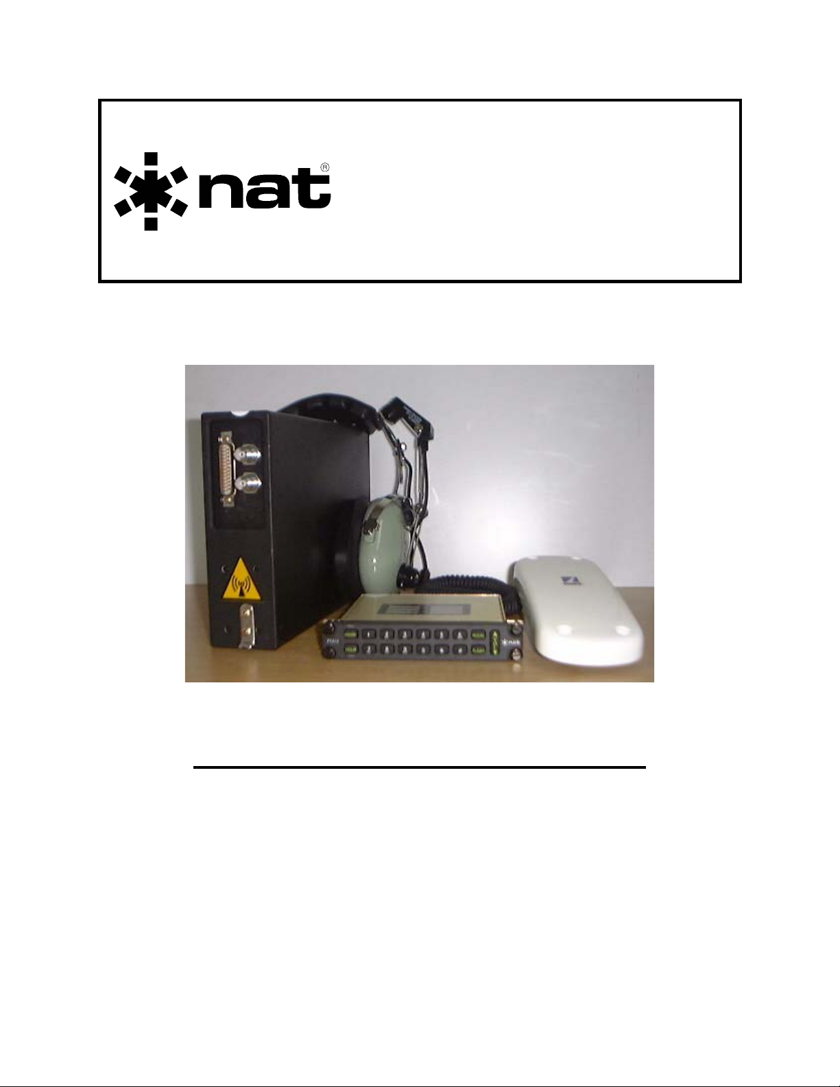
STX100-000
SM67
Globalstar™
Satphone Transceiver
INSTALLATION AND OPERATION MANUAL
REV 4.10 September 7, 2005
Northern Airborne Technology Ltd.
1925 Kirschner Road
Kelowna BC, Canada.
V1Y 4N7
Telephone (250) 763-2232
Facsimile (250) 762-3374
Copyright 2005 by Northern Airborne Technology
Page 2

Page 3

SM67 Rev. 4.10 STX100-000 Globalstar™ Satphone Transceiver Manual
IMPORTANT INFORMATION
FOR AVIONICS INSTALLATION FACILITIES
The STX100-000 Globalstar™ Satphone Transceiver is
supplied without TSO certification, as no such standard presently
exists for airborne Satphone transceivers. This equipment provides
what is considered as “supplemental” communications, and can be
installed in an aircraft on a “Non interference” basis. Installation
should be performed using standard procedures applicable to aircraft
radio installation, to ensure that the newly installed equipment does not
interfere with any other equipment in the aircraft.
This device complies with Part 15 of the FCC Rules. Operation is
subject to the condition that this device does not cause harmful
interference.
Sep 7, 2005 Page ii
ENG-FORM: 820-0104.DOT
CONFIDENTIAL AND PROPRIETARY TO NORTHERN AIRBORNE TECHNOLOGY LTD.
Page 4

Page 5
SM67 Rev. 4.10 STX100-000 Globalstar™ Satphone Transceiver Manual
Performed at factory
Periodically NAT will release manual amendments. In order to maintain the most
accurate and up to date manual these amendments should be carried out immediately
upon receipt and recorded on the following amendment record.
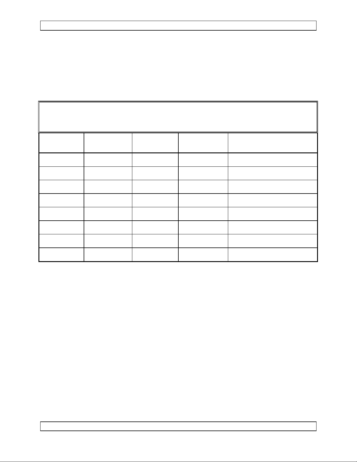
AMENDMENT RECORD
Amendment
Number
#1 Jan 25/06 2
Amendment
Date
Section(s)
Changed
Date
Entered
Entered By
Insert any Amendment Instruction sheets after this page.
Sep 7, 2005 Page iii
ENG-FORM: 820-0104.DOT
CONFIDENTIAL AND PROPRIETARY TO NORTHERN AIRBORNE TECHNOLOGY LTD.
Page 6

Page 7
INSTALL_OPS
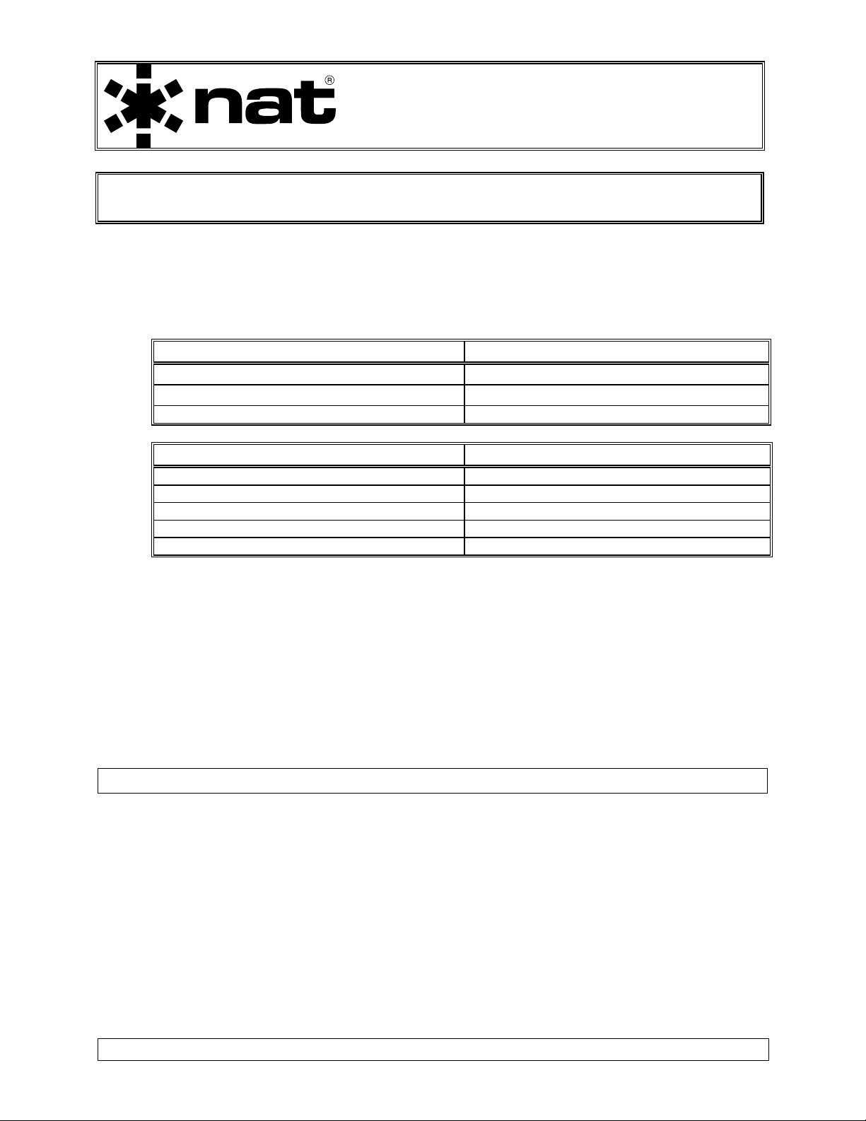
MANUAL AMENDMENT
Manual: SM67 STX100-000 Amendment #: 1
Document # SM67\Install_Ops\809-0001 Amendment Date: Jan 25, 2006
The purpose of this amendment is to make minor corrections to the Interconnect
drawings.
Amendment Instructions:
1
2
STX100\000\403-4 Rev 1.10 STX100\000\403-4 Rev 1.11
STX100\000\403-5 Rev 1.10 STX100\000\403-5 Rev 1.11
STX100\000\403-7 Rev 1.00 STX100\000\403-7 Rev 1.01
Note: Ensure that all drawings are inserted in the order shown on the latest drawing lists.
Remove Drawings (Section 2) Replace or add Drawings (Section 2)
3 Update the Amendment Record sheet at the front of the manual.
4 Insert this page into the manual after the Amendment Record sheet (page ii).
Manual Amendment ends after the following amended pages
Remove Pages Replace With Pages
2-7 and 2-8 rev 4.10 2-7 and 2-8 rev 4.10 Amendment #1
Amendment #1 Jan 25, 2006 Page 1
ENG-FORM: 809-0108.DOT
PROPRIETARY AND CONFIDENTIAL TO NORTHERN AIRBORNE TECHNOLOGY LTD.
Page 8

Page 9

SM67 Rev. 4.10 STX100-000 Globalstar™ Satphone Transceiver Manual
Table of Contents
Section Title Page
1.0 Description
1.1 Introduction 1-1
1.2 Purpose of Equipment 1-1
1.3 Features 1-2
1.4 Specifications 1-2
1.4.1 Electrical Specifications 1-2
1.4.2 Physical Specifications 1-4
1.4.3 Environmental Specifications 1-4
1.4.4 System Specifications 1-5
1.4.5 Installation Approvals 1-5
2.0 Installation
2.1 Introduction 2-1
2.2 Unpacking and Inspection 2-1
2.2.1 Warranty 2-1
2.3 Installation Procedures 2-2
2.3.1 Warnings 2-2
2.3.2 Cautions 2-2
2.3.3 Notes 2-2
2.3.4 Cable and Wiring 2-2
2.3.5 Antennas 2-4
2.3.6 Mechanical Mounting 2-5
2.3.7 Data Port 2-5
2.3.8 Post-Installation Checks 2-6
2.3.9 Post Installation EMI Test 2-7
2.4 Pilot Advisory Notice 2-7
2.5 Continued Airworthiness 2-7
2.6 Accessories Required But Not Supplied 2-8
2.7 Installation Drawings 2-8
3.0 Operation
3.1 Introduction 3-1
3.2 Operation Specifics 3-1
Sep 7, 2005 Page iv
ENG-FORM: 820-0104.DOT
CONFIDENTIAL AND PROPRIETARY TO NORTHERN AIRBORNE TECHNOLOGY LTD.
Page 10

Page 11

SM67 Rev. 4.10 STX100-000 Globalstar™ Satphone Transceiver Manual
Section 1 Description
1.1 Introduction
This manual contains information on the STX100-000 Globalstar™ Satphone
Transceiver. All derivative products will be covered by manual supplements, which can
be obtained from NAT as required.
Information in this section consists of purpose of equipment, features and specifications.
Note: The STX100-000 is shipped from NAT in a deactivated state. The unit must be
registered with and activated by Globalstar
can be attempted. Please refer to the information sheet packaged with the
STX100-000 for registration details.
1.2 Purpose of Equipment
™ before any operation of the system
The STX100-000 is a complete, self-contained airborne Satphone Transceiver for use
on the Globalstar
™ satellite communications system. The system is voice and data
capable (single channel), and is designed for use with the PTA12 POTS Telephone
Adapter and the LMC01 Latitude Mobile Controller, both manufactured by NAT Ltd.
The LMC01 is used to provide asset management and positioning capability (e.g., flight
following). The LMC01 is a remote mounted unit, and connects to the data port on the
STX100-000. The LMC01 is optional, and is set-up at time of installation to operate
automatically. Refer to the LMC/LMC01 Users Manual for more information.
The voice connection is made with a standard two-wire connection (tip/ring). This is also
referred to as a POTS (Plain Old Telephone Service) interface and is the audio path
to/from the PTA12. This will also allow connection of a standard, 2-wire handset for
cabin purposes, if needed.
Note: Due to current limitations (30 mA) on the POTS interface, the handset should be
powered from the aircraft to ensure proper operation of the system.
The data connection is through the STX100-000's data port. The data port supports
asynchronous and packet data services. Asynchronous data services allow for the
transmission of ASCII or binary data between a computer or other device connected to
the STX100-000 and any Hayes™ compatible modem connected to the Public Switched
Telephone Network (PSTN). Packet data services allow for the connection of a device
able to support a PPP session using TCP/IP. This is the typical standard used by
computers for dial-up service.
Sep 7, 2005 Page 1-1
ENG-FORM: 800-0107.DOT
CONFIDENTIAL AND PROPRIETARY TO NORTHERN AIRBORNE TECHNOLOGY LTD.
Page 12

STX100-000 Globalstar™ Satphone Transceiver Manual SM67 Rev. 4.10
1.3 Features
• Voice and Data Capable • Lightweight, Compact Tray Mount
• Easy Cockpit Integration • Aircraft Grade Enclosure
• Easy Installation & Removal for Mission & Aircraft Flexibility
The basic voice ‘system’ is comprised of three units: the STX100-000 Satcom Satphone
Transceiver, the PTA12-xxx Series control panel, and a Comant CI480-1 (or equivalent)
approved antenna. The STX100-000 is a remote mounted, 1/4 ATR type unit that is
tray mounted. Its simple interconnect allows for easy installation and operation. The
PTA12 unit replaces the typical handset and provides a direct interface to the aircraft
audio system, allowing the STX100-000 transceiver system to be selected in the same
manner as the other aircraft radios. The antenna is typically a low profile type, designed
for use with Globalstar
™ system.
The basic data system is comprised of the STX100-000, CI480-1 (or equivalent)
antenna, and the LMC01-xxx.
The heart of the STX100-000 is the Qualcomm
™ Globalstar™ Satphone Transceiver.
The STX100-IKC (crimp) install kit is needed to complete the installation. The install kit
includes the TX Filter that should be mounted near the STX100-000.
1.4 Specifications
1.4.1 Electrical Specifications
Power Supply
The STX100-000 utilizes an internal 'Quarter-Brick' DC/DC converter which
converts the supplied 28 Vdc aircraft voltage down to the 12 Vdc internal
operating voltage required by the Qualcomm transceiver.
System Input Requirements:
Voltage 27.5 Vdc nominal
30.3 Vdc maximum
22.0 Vdc minimum
18.0 Vdc Emergency Operation
Current 3.0 Amps maximum (internal fuse)
Page 1-2 Sep 7, 2005
ENG-FORM: 800-0107.DOT
CONFIDENTIAL AND PROPRIETARY TO NORTHERN AIRBORNE TECHNOLOGY LTD.
Page 13

SM67 Rev. 4.10 STX100-000 Globalstar™ Satphone Transceiver Manual
Input Signals
+28 Vdc Power Main input power
On/Off Control On - 15 mA maximum
Off - open circuit
Chassis Ground Airframe connection
RF RX 50 Ω - receive RF
TX Data Data Port serial data - Transmit Data
DTR Data Port serial data - Data Terminal Ready
RFR Data Port serial data - Ready For Receiving
DM TX Data DM Port serial data - Transmit Data
DM RTS DM Port serial data - Request To Send
Output Signals
Power Ground Main input power ground
RF TX 50 Ω - transmit RF, 2 W maximum
RLSD Data Port serial data - Received Line Signal Detect
RX Data Data Port serial data - Receive Data
CTS Data Port serial data - Clear To Send
RI Data Port serial data - Ring Indicator
DM RX Data DM Port serial data - Receive Data
DM CTS DM Port serial data - Clear To Send
Bi-directional Signals
Tip POTS
Ring POTS
Shield POTS
Serial Ground Data Port serial data – Signal Ground
DM Serial Ground DM Port serial data – Signal Ground
Sep 7, 2005 Page 1-3
ENG-FORM: 800-0107.DOT
CONFIDENTIAL AND PROPRIETARY TO NORTHERN AIRBORNE TECHNOLOGY LTD.
Page 14

STX100-000 Globalstar™ Satphone Transceiver Manual SM67 Rev. 4.10
1.4.2 Physical Specifications
Depth 11.20" (284.5 mm) maximum
Height 7.25" (184.2 mm) maximum
Width 2.26" (57.4 mm) maximum
Weight 7.35 lbs (3.3 kg) maximum
Mounting Tray (NTX-VT1)
Material 5052-H32 Aluminum alloy (Top and Bottom Covers)
6061-T6 Aluminum alloy (all other pieces)
Finish Black anodized (exposed surfaces)
per MIL-A-8625 Type III Class 2
Clear chromate conversion (internal chassis and
connector/contact areas)
Connectors One 25-pin male D-subminiature with V5 locking H/W
Two TNC female bulkhead
Installation Kit STX100-IKC
1.4.3 Environmental Specifications
Qualification:
Temperature
(Operating) -30° C to +60° C
(Survival) -40° C to +85° C
Altitude 50,000 ft
Humidity 95%
Shock DO-160D Cat. B
Vibration DO-160D Cat. (SM)
DO-160D Env. Cat. [A4]-BAB(SM)XXXXXXABBXXXLXXXX
Industry Canada Approval: IC:993B-STX100
FCC Approval: Verification to FCC Part 25
Compliance to FCC Part 15
Page 1-4 Sep 7, 2005
ENG-FORM: 800-0107.DOT
CONFIDENTIAL AND PROPRIETARY TO NORTHERN AIRBORNE TECHNOLOGY LTD.
Page 15

SM67 Rev. 4.10 STX100-000 Globalstar™ Satphone Transceiver Manual
1.4.4 System Specifications
Functional Limits
Uplink Band (reverse link) 1610.73 - 1625.49 MHz
Downlink Band (forward link) 2484.39 - 2499.15 MHz
Certification Limits
Uplink Band (reverse link) 1610.5 - 1621.35 MHz
Downlink Band (forward link) 2483.5 - 2500.0 MHz
Operating Mode Full Duplex
RF Input/Output Impedance 50 Ω
Remote Interface POTS
Data Interface Data Port – RS-232
(19200 baud fixed, 8-N-1, hardware)
RF Power Output 2 W maximum (+33 dBm)
1.4.5 Installation Approvals
TC STC No. SA02-64
FAA STC No. ST01824NY
TC STC No. SA03-63
End of section 1
Diagnostic Monitor (DM) Port – RS-232
(115200 baud fixed, 8-N-1, hardware)
Sep 7, 2005 Page 1-5
ENG-FORM: 800-0107.DOT
CONFIDENTIAL AND PROPRIETARY TO NORTHERN AIRBORNE TECHNOLOGY LTD.
Page 16

Page 17

SM67 Rev. 4.10 STX100-000 Globalstar™ Satphone Transceiver Manual
Section 2 Installation
2.1 Introduction
Information in this section consists of: unpacking and inspection procedures, installation
procedures, post-installation checks, and installation drawings.
2.2 Unpacking and Inspection
Unpack the equipment carefully, and locate the warranty card. Inspect the unit visually
for damage due to shipping and report all such claims immediately to the carrier
involved. Note that each unit should have the following:
- STX100-000 Globalstar
- Warranty Card
- Release certification
Verify that all items are present before proceeding, and report any shortage immediately
to your supplier.
Note: The STX100-000 is shipped from NAT in a deactivated state. The unit must be
registered with and activated by Globalstar™ before any operation of the system
can be attempted. Please refer to the information sheet packaged with the
STX100-000 for registration details.
™ Satphone Transceiver
2.2.1 Warranty
Complete the warranty card information and send it to NAT when the installation is
complete. If you fail to complete the warranty card, the warranty will be activated on
date of shipment from NAT.
Note: An appropriately rated facility, e.g. Certified Aircraft Repair Station, must install
this equipment in accordance with applicable regulations. NAT Ltd’s warranty is
not valid unless the equipment is installed by an authorized NAT Dealer. Failure
to follow any of the installation instructions, or installation by a non-certified
individual or agency will void the warranty, and may result in a non-airworthy
installation.
CAUTION:
Any changes or modifications to this equipment not expressly
approved by Northern Airborne Technology Ltd could void the
user's authority to operate the equipment.
Sep 7, 2005 Page 2-1
ENG-FORM: 805-0106.DOT
CONFIDENTIAL AND PROPRIETARY TO NORTHERN AIRBORNE TECHNOLOGY LTD.
Page 18

STX100-000 Globalstar™ Satphone Transceiver Manual SM67 Rev. 4.10
2.3 Installation Procedures
2.3.1 Warnings
Do not bundle any lines from this unit with transmitter coax lines. Do not bundle any
logic, audio, or DC power lines from this unit with 400 Hz synchro wiring or AC power
lines. Do not position this unit next to any device with a strong alternating magnetic field
such as an inverter or significant interference to operation will result. In all installations,
use shielded cable exactly as shown
and ground as indicated. Significant problems
may result if these guidelines are not followed.
2.3.2 Cautions
All audio installations can be severely degraded by incorrect wiring and shielding, and
may result in much higher cross-talk, hum, and ground-loop interference. This should
be considered when audio wiring to and from the radio system installation is performed.
In communication intensive applications, poor cable routing and shielding may drastically
compromise over-all system performance. Use caution in the routing of wire bundles.
The STX100-000 can be connected to and used with a 2-wire handset, however the
handset current must not exceed 30 mA due to restrictions in the loop current available
from the 2-wire POTS interface in the STX100-000. The handset should be powered
from the aircraft’s electrical buss to ensure proper operation of the satphone system.
2.3.3 Notes
The case of the STX100-000 must be electrically grounded for maximum resistance to
low frequency interference. Pin 16
(CHASSIS GROUND) on connector P103 is provided
and must be connected by a short wire to a clean ground, not jumpered to the power
ground wire connection.
2.3.4 Cable and Wiring
All unshielded wire shall be selected in accordance with AC43.13-1B Change 1,
Paragraphs 11-76 through 11-78. Wire types should be to MIL-W-22759 as specified in
AC43.13-1B Change 1, Paragraphs 11-85, 11-86, and listed in Table 11-11. For
shielded wire applications, use Tefzel MIL-C-27500 shielded wire with solder sleeves
(for shield terminations) to make the most compact and easily terminated interconnect.
Follow the wiring diagrams in Section 2.7 as required.
All wiring should be 22 AWG minimum, except power and ground connections, which
must be 18 AWG or larger, as indicated on the installation drawings. Ensure that the
ground connection is clean and well secured. To prevent inadvertent system failure,
power to this system must be supplied from a separate breaker or fuse and not
connected to any other device. A 5 A fuse or breaker is recommended (28 Vdc).
Allow 3 inches from the end of the wire to the shield termination to allow the hood to be
easily installed. Note that the hood is installed after the wiring is complete.
Page 2-2 Sep 7, 2005
ENG-FORM: 805-0106.DOT
CONFIDENTIAL AND PROPRIETARY TO NORTHERN AIRBORNE TECHNOLOGY LTD.
Page 19

SM67 Rev. 4.10 STX100-000 Globalstar™ Satphone Transceiver Manual
Fabrication & installation of wiring harness should be in accordance with AC 43.13-1B,
chapter 11, sections 5-12.
Grounding and bonding should be in accordance with AC 43.13-1B, chapter 11, section 15.
2.3.4.1 Coaxial Cables
The RF budget for the STX100-000 is very specific for both the RX and TX paths. The
type and length of coaxial cable is critical in order to achieve proper performance of the
STX100-000 system. It is recommended that the coaxial cables be sourced from a
vendor that specializes in the fabrication of low loss cable sets. Refer to Tables 2-1 and
2-2 for examples.
Coaxial cable should be in accordance with MIL-C-17 unless otherwise specified. Do
not use coax with PVC insulation. Teflon dielectric cable is recommended at or above
UHF frequencies or where cable runs exceed 8 feet. Note that at these frequencies, cable
losses due to long cable runs and tight bends may cut the ERP (Equivalent Radiated
Power) to less than 50% of specification.
RF cables must be neatly terminated (solder or crimp), and tested for shorts prior to system
check-out (not while connected to the radio or antenna). Keep cable bends to a minimum
at the antenna. Avoid sharp bends in the coax cables to prevent severe reflections. If
sharp bends are required, use 90° elbow adapters.
When routing the coaxial cables make sure they are properly identified as they use the
same connector for both the RX and TX connections at the STX100-000. This can also be
true of the antenna, depending on the model used for the installation.
2.3.4.2 Cable Lengths
The transmit and receive coaxial cables and TX Filter have a minimum and maximum
signal loss that must be taken into consideration. Exceeding the min/max signal
strength by having an improper coax length may cause poor system performance. For
reference, the calculations are based on a transmit frequency of 1.6 GHz, and a receive
frequency of 2.5 GHz.
Transmitter path loss (min): 1.35 dB * Receiver path loss (min): 1.50 dB
Transmitter path loss (max): 2.15 dB ** Receiver path loss (max): 8.50 dB
* Includes the transmitter filter insertion loss (nom) of 1.8 dB.
** Includes the transmitter filter insertion loss (max) of 2.0 dB.
The tables below identify examples of coax cable types that can be used and shows the
min/max cable lengths for that type. The calculations take into consideration the losses
associated with the transmitter filter (transmit cable only) but they do not take into
consideration the losses associated with the coaxial connectors. Any other quality coax
cable can be used provided it meets the requirements for min/max cable loss.
Sep 7, 2005 Page 2-3
ENG-FORM: 805-0106.DOT
CONFIDENTIAL AND PROPRIETARY TO NORTHERN AIRBORNE TECHNOLOGY LTD.
Page 20

STX100-000 Globalstar™ Satphone Transceiver Manual SM67 Rev. 4.10
Table 2-1 Example of Transmit Cable Calculations
Part Number Cable OD Bend Radius Min (1.35 dB) Max (2.15 dB) 1.6 GHz
Units Mil's Inches Feet Feet DB/Foot
ECS Cable
311201 317 1.59 20.1 32.1 0.067
310801 452 2.26 28.7 45.7 0.047
8C0500 630 5 45.0 71.7 0.030
PIC Wire&Cable
S55122 300 1.6 19.0 30.3 0.071
S22089 435 2.5 27.6 43.9 0.049
Table 2-2 Example of Receive Cable Calculations
Part Number Cable OD Bend Radius Min (1.50 dB) Max (8.50 dB) 2.5 GHz
Units Mil's Inches Feet Feet DB/Foot
ECS Cable
311901 195 1 8.1 45.9 0.185
311601 229 1.15 11.5 65.4 0.130
311501 229 1.2 13.9 78.7 0.108
PIC Wire&Cable
S86208 130 0.65 6.3 35.8 0.2375
S88207 130 0.65 6.5 37.0 0.230
S44191 195 1 7.6 43.1 0.197
S44193 195 1 8.2 46.6 0.1825
S67163 230 1.2 12.9 73.3 0.116
2.3.5 Antennas
Correct antenna placement and mounting is critical in order to achieve the best possible
performance. In general, keep all antennas as widely separated as possible and clear
of any large airframe obstructions.
Installation of the antenna should be in accordance with AC 43.13-1B, chapter 4,
section 4, and AC 43.13-2A chapter 3. If possible, the antenna should be located a
minimum of 8 feet from aircraft navigation receiver antennas and a minimum of 4 feet
from aircraft communications and ELT antennas.
Note: The STX100-000 antenna should be located a minimum of 6’ from the GPS
antenna, and MUST be top mounted (satellite view).
Avoid antenna locations that may become fouled with oil, water, fuel or dirt, as this will
degrade performance.
CAUTION:
Ensure that the unit is mounted in a location where the general population will
not approach within 8 inches (20cm) of the transmitting antenna. This distance
provides an additional safety margin for the product.
Page 2-4 Sep 7, 2005
ENG-FORM: 805-0106.DOT
CONFIDENTIAL AND PROPRIETARY TO NORTHERN AIRBORNE TECHNOLOGY LTD.
Page 21

SM67 Rev. 4.10 STX100-000 Globalstar™ Satphone Transceiver Manual
2.3.6 Mechanical Mounting
The STX100-000 is a tray-mounted device and uses a standard 1/4 ATR style tray.
Mount (with counter-sunk screws) onto a clean, grounded surface having a resistance
of less than 0.5 ohms to airframe ground. The STX100-000 may be mounted in any
attitude, but upright (mounting hook at the bottom) is preferred for access and
condensation drainage.
The TX Filter Assembly should be mounted in close proximity to the STX100-000. The TX
Filter is supplied as part of the STX100-IKC install kit, which also includes the base plate
and associated hardware that can be used to provide a convenient method of mounting
the TX Filter. The TX Filter (with base plate attached) is secured with four 10-32 screws.
Installation of the STX100-000, its mounting tray, and the TX Filter should be in
accordance with AC 43.13-1B, chapter 4, section 4, and AC 43.13-2A, chapter 2. Ensure
adequate space is available to allow airflow around the STX100-000 unit.
2.3.7 Data Port
The Data Port allows the user to connect a computer to the STX100-000 to access data
services. There are 2 types of data services handled by the Data Port: Asynchronous,
and Packet Data. For both of these services, the equipment interfacing to the STX100000 must be configured for 19200-baud, 8 bits, 1 stop bit, no parity, and hardware
handshaking, with EIA/TIA RS-232 standard signal levels.
Note: The STX100-000 is shipped from NAT in a deactivated state. The unit must be
registered with and activated by Globalstar™ before the following tests can be
conducted. Please refer to the information sheet packaged with the STX100-000
for registration details.
2.3.7.1 Asynchronous Services
Asynchronous Services establishes a data connection between a computer or other
device connected to the data port, and any Hayes compatible modem that is connected
to the Public Switched Telephone Network. The connection between the device and the
remote modem is accomplished by dialing the number of the remote modem from the
AT command line (i.e. ATD18883359533 <ENTER>). Once the connection is
established between the 2 modems, binary data, or ASCII data can be transmitted.
Sending the "+++" followed by a delay of longer than 1 second, followed by "ATH"
terminates the connection.
2.3.7.2 Packet Services
The data connection is established by the computer issuing a dialing command
"ATD#777<enter>". This starts a PPP session using the TCP/IP protocol. Sending the
"+++" followed by a delay of longer than 1 second, followed by "ATH" terminates the
connection.
Sep 7, 2005 Page 2-5
ENG-FORM: 805-0106.DOT
CONFIDENTIAL AND PROPRIETARY TO NORTHERN AIRBORNE TECHNOLOGY LTD.
Page 22

STX100-000 Globalstar™ Satphone Transceiver Manual SM67 Rev. 4.10
The PPP connection using TCP/IP can be set up as a standard Windows Dial Up
networking connection or it can be part of the connecting application. When you use
Packet Data service, Globalstar™ acts as your Internet Service Provider (ISP).
Contact Globalstar
™ for more information on Data Services and system configuration
requirements. You can also check their website (www.globalstar.com) for details and
FAQ's on Data Services.
2.3.8 Post-Installation Checks
2.3.8.1 Voltage/resistance checks
Do not attach the STX100-000 until the following conditions are met.
Check the following:
a) P103 pins <1> and <2> for +28 Vdc relative to ground.
b) P103 pins <14>, <15>, and <16> for continuity to ground (below 0.5 Ω).
Ensure that the antenna is disconnected for the following test or erroneous
readings may be obtained.
c) Radio coax connectors (RX and TX) for continuity to the antenna coax connector
(shield and center conductor), and for open circuit from the center conductor to
ground and open circuit from the center conductor to the shield.
Note: The STX100-000 is shipped from NAT in a deactivated state. The unit must be
registered with and activated by Globalstar™ before the following tests can be
conducted. Please refer to the information sheet packaged with the STX100-000
for registration details.
2.3.8.2 Power On Checks, Voice
a) Install the STX100-000 and associated components. Power up the aircraft’s
systems, and make the necessary selections on the audio control panel(s) to
select the STX100-000 system for voice operation.
b) With the aircraft outside the hangar, use the PTA12 control panel (and/or
handset) to initiate a call and establish two-way communications.
Note: You can place a free (no air-time charge) ‘test call’ to the local gateway by
dialing #8378. If the call is successfully completed, you will hear a
recorded message from the gateway, welcoming you to the Globalstar™
system.
Page 2-6 Sep 7, 2005
ENG-FORM: 805-0106.DOT
CONFIDENTIAL AND PROPRIETARY TO NORTHERN AIRBORNE TECHNOLOGY LTD.
Page 23

SM67 Rev. 4.10 STX100-000 Globalstar™ Satphone Transceiver Manual
c) Check the operation of the VOL, HOLD, REDIAL and FLASH functions on the
PTA12.
d) Request the ‘called party’ to place a call to the aircraft, and confirm ringer
operation and incoming call functions.
2.3.8.3 Power On Checks, Data
a) Following completion of the Voice tests, connect a laptop computer to the data
port on the STX100-000 (this assumes the data port connections are accessible
and allow for easy connection to the laptop).
b) Using a terminal emulator program (i.e. HyperTerminal, TerraTerm, etc.) with the
serial port correctly set to communicate with the STX100-000 (19,200 baud, 8
Bit, 1 Stop Bit, No Parity), type AT <Enter>. You should get an OK back from the
STX100-000, verifying the data port wiring is correct and that you can
communicate with the internal modem of the STX100-000.
Once you have verified connection with the modem, you can test the PPP connection
using TCP/IP. Confirm you have correctly set the modem and dial-up networking
connections, and that you have a working ISP before proceeding with the test.
2.3.9 Post Installation EMI Test
The purpose of this test is to identify any interference that the STX100-000 may cause
with existing aircraft systems. The STX100-000 should be tested in accordance with the
Installation Approval Test Procedure listed in section 2.7, and the test results
documented on the record sheets.
Upon satisfactory completion of all performance checks, make the required log
entries and complete the necessary Regulatory Agency paperwork before
releasing the aircraft for service.
2.4 Pilot Advisory Notice
The operating equipment associated with the STX100-000 Globalstar™ Satphone
Transceiver equipment must be placarded, in clear view of the pilot, with the following:
SATPHONE NOT TO BE USED FOR ATC PURPOSES
DO NOT USE ON GROUND DURING REFUELING
2.5 Continued Airworthiness
Maintenance of the STX100-000 is ‘on condition’ only. Periodic maintenance of this
product is not required.
Sep 7, 2005 Page 2-7
ENG-FORM: 805-0106.DOT Amendment #1 Jan 25, 2006
CONFIDENTIAL AND PROPRIETARY TO NORTHERN AIRBORNE TECHNOLOGY LTD.
Page 24

STX100-000 Globalstar™ Satphone Transceiver Manual SM67 Rev. 4.10
2.6 Accessories Required But Not Supplied
Installation kit p/n STX100-IKC (crimp) is required to complete the installation. It
consists of the following:
STX100-IKC:
Quantity Description NAT Part #
1 D-min 25 Socket housing 20-21-025
25 MS Crimp Socket 20-26-901
1 25 Pin JVL Hood/Locklever 20-29-250
1 Vertical Mount Tray NTX-VT1
1 Base plate 50-08-026
1 TX Filter 54-04-001
6 6-32 Screw, Flathead 25-13-016
2.7 Installation Drawings
DRAWING REV. DESCRIPTION TYPE SERIAL #
STX100\306-0 1.00 STX100 Satcom System Block Diagram System
Configuration All
STX100\000\403-1 1.10 STX100 Globalstar™ Satphone Transceiver Interconnect All
STX100\000\403-2 1.10 STX100 Globalstar™ Satphone Transceiver Interconnect All
STX100\000\403-3 1.10 STX100 Globalstar™ Satphone Transceiver Interconnect All
STX100\000\403-4 1.11 STX100 Globalstar™ Satphone Transceiver Interconnect All
STX100\000\403-5 1.11 STX100 Globalstar™ Satphone Transceiver Interconnect All
STX100\000\403-6 1.00 STX100 Globalstar™ Satphone Transceiver Interconnect All
STX100\000\403-7 1.01 STX100 Globalstar™ Satphone Transceiver Interconnect All
STX100\000\405-0 1.10 STX100 Globalstar™ Satphone Transceiver Connector Map All
STX100\000\634-0 1.00 Post Installation EMI Test Installation Approval Test Procedure All
STX100\000\922-0 1.20 STX100 Globalstar™ Satphone Transceiver Mechanical Up to 2048
STX100\000\922-0 1.30 STX100 Globalstar™ Satphone Transceiver Mechanical 2049 and up
NTX-VT1\922-0 1.00 Vertical Mount Tray Mechanical All
5404002\952-0 1.00 TX Filter Assembly Mechanical All
Section 2 ends after these Drawings
Page 2-8 Sep 7, 2005
ENG-FORM: 805-0106.DOT Amendment #1 Jan 25, 2006
CONFIDENTIAL AND PROPRIETARY TO NORTHERN AIRBORNE TECHNOLOGY LTD.
Page 25

Page 26

Page 27

Page 28

Page 29

Page 30

Page 31

Page 32

Page 33

Page 34

Page 35

Page 36

Page 37

Page 38

Page 39

Page 40

Page 41

Page 42

Page 43

INSTALLATION APPROVAL
NAT Part #: STX100-000
Document #: STX100\000\634-0 Rev: 1.00
1.0 Introduction
The purpose of this test is to identify any interference that the STX100-000 Globalstar™
Satphone Transceiver may cause with existing aircraft systems.
1.1 Test Conditions
The STX100-000 should be installed and function tested in accordance with the
STX100-000 Globalstar™ Satphone Transceiver Installation and Operation manual.
1.2 Methodology
Most of the EMI tests can be accomplished on the ground. In some cases, flight-testing is
required or is easier. If the aircraft is approved for IFR operations, then it is mandatory
that interference between the STX100-000 and the approach aids be checked in flight.
The GPS should be operational and navigating with at least the minimum complement of
satellites. VOR/ILS/GS receivers should be set to the test frequencies and selected for
display. If possible, set up a VOR/ILS ramp test set on the test frequencies and adjust the
output until the flags are out of view. The transponder and encoder should be monitored with
ramp test equipment. If possible set the ADF to a nearby navigation station.
Modulate the STX100-000 transmitter for at least 20 seconds. Observe the GPS for any
degradation in satellite status or availability or flags. Listen for any noise or detected
audio signals on the VHF comm(s). Listen for any noise or detected audio signals on
the VOR/LOC receiver audio; look for any movement of flags or needles on the
VOR/LOC/GS navigation display(s).
Monitor the power plant, fuel and other electric instruments in the chart provided and
note any anomalies that occur while operating the STX100-000. Assess the results.
If the aircraft is equipped with an Automatic Flight Control or Stability Augmentation
System, test fly the aircraft and verify that the operation of the STX100-000 Satphone
Transceiver does not have adverse effects on these systems. After checking for gross
effects at a safe altitude, fly an approach with each of the different navigation systems
coupled to the autopilot (ILS, GPS etc.) and look for any anomalies.
1.3 Results
TEST PROCEDURE
Description: Globalstar
™ Satphone Transceiver
If the installed system passes all of the applicable EMI tests, then no further action is
required. If interference is observed, then the interference must be assessed against
Rev. 1.00 May 24, 2002 Page 1 of 4
ENG-FORM: 634-0100.DOT
CONFIDENTIAL AND PROPRIETARY TO NORTHERN AIRBORNE TECHNOLOGY LTD.
Page 44

STX100-000 Installation Approval Test Procedure
the appropriate standards of airworthiness for the system in question. For example: it is
permissible for a VFR certified GPS to lose navigation capability while the STX100-000
is transmitting, providing that it recovers properly and promptly, but it is not permissible
for an IFR Approach certified GPS to be affected in the same way. A complete
discussion of all the standards of airworthiness to be applied in assessing EMI effects is
beyond the scope of this document.
2.0 System Ground functional Tests
Prior to connecting equipment and commencing system ground functional tests, ensure
that system point-to-point wire checks and system power checks have been completed.
Prior to turning on aircraft power ensure all system circuit breakers and all system
controls ON/OFF switches are in the OFF position.
2.1 Electrical Power
a. Apply electrical DC power to aircraft as per the aircraft maintenance manual.
b. Check for Power, Ground and Lights at the following points:
Equipment Connector
or Termination
PTA12-000
Telephone
Adaptor
STX100-000
Globalstar™
Satphone
Transceiver
-1, -2
-14, -15, -16
-3
-1, -2
-3, -14, -15,
-16
Voltage
Readout
28 Vdc
Gnd
28 Vdc Lights
28 Vdc
Gnd
Control Circuit
Breaker
As per aircraft
installation data
As per aircraft
installation data
Results
c. Connect electrical equipment.
2.2 STX100-000 System
The STX100-000 will be checked out as follows:
a. Push in STX100-000 system circuit breakers.
b. Select STX100-000 on the pilot and co-pilot’s audio panels.
c. Dial a phone number using the PTA12 and establish two-way communication.
Test the VOL, HOLD, REDIAL and FLASH functions. Ask the call recipient to
phone back to confirm operation of the ringer function.
Page 2 of 4 May 24, 2002 Rev. 1.00
E NG-FORM: 634-0100.DOT
CONFIDENTIAL AND PROPRIETARY TO NORTHERN AIRBORNE TECHNOLOGY LTD.
Page 45

STX100-000 Installation Approval Test Procedure
3.0 GROUND FUNCTION TEST SPECIFICATION - EMI/RFI Testing
3.1 Scope
This document provides guidance for conducting ground procedures and EMI/RFI
testing of an aircraft’s added or removed electrical equipment.
3.2 Acceptance Criteria
While performing testing, the systems under test (i.e. the added equipment) are
considered to have passed if the aircraft instrument and data displays and/or equipment
operate normally and NO failing criteria, as described below, are witnessed.
The System Under Test (SUT) passes if the existing aircraft system only indicates a
momentary flicker or slight movement of the display, as long as the movement is not a
permanent displacement.
The SUT passes if evidence of interference can be determined only by an audible
change of aircraft speaker and/or headsets and the change exhibits a ‘pop’ or other
transitory noise when the SUT is operated in its various modes.
The SUT passes from the standpoint of Automatic Flight Control and Stability
Augmentation System equipment if the SUT does not cause a detectable response from
these flight control systems.
3.3 Ground Test Procedures
All tests may be performed using an external power source, or during a ground engine
run with all electrical systems on line and operating normally.
With the equipment power connectors disconnected, apply ground power and
energize the circuit breakers.
Using the wiring diagram, verify the voltage (power in, and ground) at each of the added
components’ power and ground terminals. Determine, record and correct all
discrepancies before continuing.
Note: During the next step observe the aircraft electrical load meter and verify that it
stays within safe operating range and does not exceed the aircraft’s electrical
generating capacity.
Energize the individual items of the system being installed, one at a time, and apply
power to each. Ensure that each system is operating correctly, referring to equipment
installation and operation manuals for correct operation procedures.
Rev. 1.00 May 24, 2002 Page 3 of 4
E NG-FORM: 634-0100.DOT
CONFIDENTIAL AND PROPRIETARY TO NORTHERN AIRBORNE TECHNOLOGY LTD.
Page 46

STX100-000 Installation Approval Test Procedure
3.4 EMI Testing
Perform an EMI ground test with engine(s) operating, using the criteria in section 3.2
above; with all additional equipment required by the newly installed system.
Note: All of the equipment in the table below may not be present in the aircraft.
Operate and observe the following aircraft systems for anomalies.
Note: Data observed should be reasonable and stable, and equipment operation
should be normal.
(Equipment not installed should be noted in the comments column. T=Threat, V=Victim)
System to be Verified Pass/fail Comments
VHF Comm. (T/V)
VHF Nav (T/V)
ILS (T/V)
NAV. Equipment (T/V)
GPS system (T/V)
Cockpit Displays (T/V)
Cockpit and Cabin Audio
Cockpit Voice Recorder (T/V)
Marker Beacon (T/V)
ADF (T/V)
Transponders (T/V)
Loud hailer (T only)
Heading Source (T/V)
Air Data System (T/V)
Automatic Pilot/Flight Director (T/V)
ELT (Do not test for threat)
Resource tracking (T only)
VHF FM (T only)
UHF FM (T only)
OTHER
OTHER
OTHER
End of Installation Approval Test Procedure
Page 4 of 4 May 24, 2002 Rev. 1.00
E NG-FORM: 634-0100.DOT
CONFIDENTIAL AND PROPRIETARY TO NORTHERN AIRBORNE TECHNOLOGY LTD.
Page 47

Page 48

Page 49

Page 50

Page 51

Page 52

Page 53

Page 54

Page 55

SM67 Rev. 4.10 STX100-000 Globalstar™ Satphone Transceiver Manual
Section 3 Operation
3.1 Introduction
Information in this section consists of the functional and operational procedures for the
STX100-000 Globalstar
3.2 Operation Specifics
The STX100-000 Globalstar
operational aspects.
All operational functions of the STX100-000 Globalstar
controlled by the NAT PTA12 POTS Telephone Adapter, and/or a standard 2-wire
aviation handset. Complete information for the PTA12 can be found in the PTA12
Operator’s manual.
Additionally, the STX100-000 can be controlled by the LMC01 Latitude Mobile
Controller, which is used to provide asset management and positioning capability (e.g.,
flight following). The LMC01 is a remote mounted unit, and connects to the data port on
the STX100-000. The LMC01 is optional, and is set-up at time of installation to operate
automatically. Refer to the LMC/LMC01 Users Manual for more information.
If further information is required, please contact the Product Support department at NAT Ltd.
Any changes or modifications to this equipment not expressly
approved by Northern Airborne Technology Ltd could void the
user's authority to operate the equipment.
™ Satphone Transceiver.
TM
Satphone Transceiver has no normal user
CAUTION:
End of section 3
™ Satphone Transceiver are
Sep 7, 2005 Page 3-1
ENG-FORM: 806-0106.DOT
CONFIDENTIAL AND PROPRIETARY TO NORTHERN AIRBORNE TECHNOLOGY LTD.
Page 56

 Loading...