

Page 1
Part of
SM15
RS12/RS24
Remote Switch
INSTALLATION AND OPERATION MANUAL
REV 4.00 November 24, 2003
Northern Airborne Technology Ltd.
1925 Kirschner Road
Kelowna BC, Canada
V1Y 4N7
Telephone (250) 763-2232
Facsimile (250) 762-3374
Copyright 2003 by Northern Airborne Technology
CONFIDENTIAL AND PROPRIETARY TO NORTHERN AIRBORNE TECHNOLOGY LTD.
Page 2

Page 3

SM15 Rev. 4.00 RS12/RS24 Remote Switch Manual
Performed at factory
Sections 1.0 through 3.0 of this Manual are
APPROVED by Transport Canada as
complying with the requirements of AWM511
for Appliance Type Certificate AP-46.
Periodically NAT will release manual amendments. In order to maintain the most
accurate and up to date manual these amendments should be carried out immediately
upon receipt and recorded on the following amendment record.
AMENDMENT RECORD
Amendment
Number
Amendment
Date
Section(s)
Changed
Date
Entered
Entered By
1 May 12/05 1-2
Insert any Amendment Instruction sheets after this page.
Nov 24, 2003 Page ii
ENG-FORM: 820-0109.DOT
CONFIDENTIAL AND PROPRIETARY TO NORTHERN AIRBORNE TECHNOLOGY LTD.
Page 4

Page 5
INSTALL_OPS
MANUAL AMENDMENT
Manual: SM15 (RS12/RS24) Amendment #: 1
Document # SM15\Install_Ops\809-0001 Amendment Date: May 12, 2005
The purpose of this amendment is to update Section 1.0 with environmental information
and descriptions of new products and add updated drawings and documents to and
remove obsolete drawings from Section 2.0
Amendment Instructions:
1
1-3 and 1-4 Rev. 4.00 1-3 through 1-5 Rev. 4.00 Amendment 1
2-1 through 2-3 Rev. 4.00 2-1 through 2-3 Rev. 4.00 Amendment 1
2
RS12\020\403-0 Rev. 1.01 RS12\020\403-0 Rev. 1.02
RS12\020\403-1 Rev. 1.01 RS12\020\403-1 Rev. 1.02
RS12\030\403-0 Rev. 1.01 RS12\030\403-0 Rev. 1.02
RS12\030\403-1 Rev. 1.01 RS12\030\403-1 Rev. 1.02
RS12\350\403-0 Rev. 1.00
RS12\350\403-0 Rev. 1.01
RS12\020\405-0 Rev. 1.01 RS12\020\405-0 Rev. 1.02
RS12\020\922-0 Rev. 1.02 RS12\020\922-0 Rev. 1.04
RS24\020\922-0 Rev. 1.02 RS24\020\922-0 Rev. 1.03
RS12\521-0 Rev. 1.10
RS24\521-0 Rev. 1.10
Remove Drawings (Section 2) Replace or add Drawings (Section 2)
Remove Pages Replace With Pages
Note: Ensure that all drawings are inserted in the order shown on the latest drawing lists.
3 Update the Amendment Record sheet at the front of the manual.
4 Insert this page into the manual after the Amendment Record sheet (page ii).
Manual Amendment ends after the following amended pages
Amendment #1 May 12, 2005 Page 1
ENG-FORM: 809-0109.DOT
CONFIDENTIAL AND PROPRIETARY TO NORTHERN AIRBORNE TECHNOLOGY LTD.
Page 6

Page 7

SM15 Rev. 4.00 RS12/RS24 Remote Switch Manual
Table of Contents
Section Title Page
1.0 Description
1.1 Introduction 1-1
1.2 Purpose of Equipment 1-1
1.3 Features 1-1
1.4 Specifications 1-2
1.4.1 Electrical Specifications 1-2
1.4.2 Physical Specifications 1-2
1.4.3 Environmental Specifications 1-3
1.5 Unit Nomenclature 1-3
2.0 Installation
2.1 Introduction 2-1
2.2 Unpacking and Inspection 2-1
2.3 Installation Procedures 2-1
2.3.1 Warnings 2-1
2.3.2 Notes 2-1
2.3.3 Cabling and Wiring 2-2
2.3.4 External Switches and Lamps 2-2
2.3.5 Post-Installation Checks 2-2
2.4 Continued Airworthiness 2-3
2.5 Installation Drawings 2-3
3.0 Operation
3.1 Introduction 3-1
3.2 General 3-1
3.3 Limitations 3-1
3.4 Emergency Procedures 3-1
3.5 Performance 3-1
Nov 24, 2003 Page iii
ENG-FORM: 820-0109.DOT
CONFIDENTIAL AND PROPRIETARY TO NORTHERN AIRBORNE TECHNOLOGY LTD.
Page 8

Page 9

SM15 Rev. 4.00 RS12/RS24 Remote Switch Manual
Section 1.0 Description
1.1 Introduction
This manual contains information on the RS12/RS24 Remote Switch. Information in this
section consists of purpose of equipment, features and specifications and a listing of all
models available to date of publication.
1.2 Purpose of Equipment
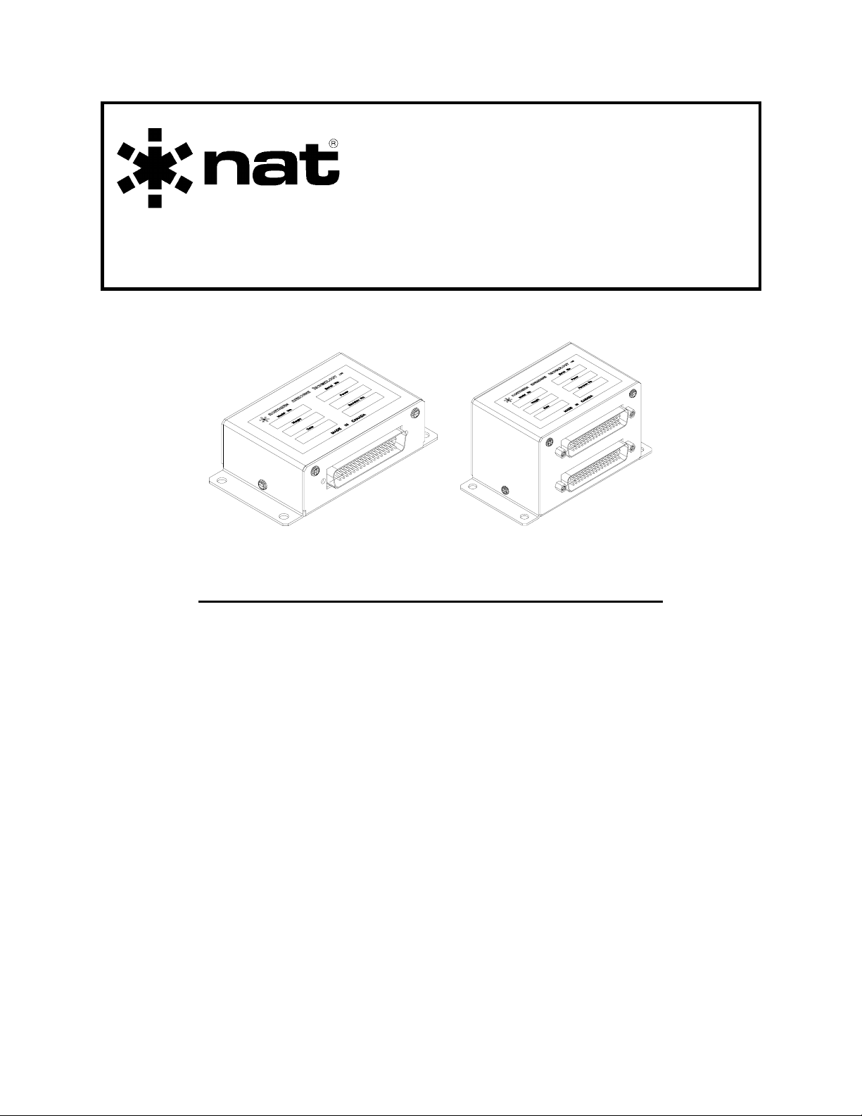
The RS12/RS24 are compact, high density, bulkhead mounted remote switching units
designed to handle the switching requirements of navaid, audio, or other interface
applications.
The RS12 remote switch is a unique interface device that allows large numbers of data
or audio lines to be transferred with a single logic level control line. The RS24 consists
of two completely independent RS12 units packaged in one enclosure.
1.3 Features
The RS12 provides switching for 12 poles of information, organized as three 4PDT
relays, each with an individual key line. Each relay can be used independently, or can
be picked as one group of three relays (12 contact sets) by applying the required logic
level to the respective ALL KEY line.
The RS24 provides switching for 24 poles of information, organized as six 4PDT relays,
each with an individual key line. Each relay can be used independently, can be picked
as two groups of three relays (12 contact sets), or can be picked as one group of six
relays by applying the required logic level to the respective ALL KEY line(s).
These relays can be used for applications from dry circuit to 0.5 A switching, but are
limited to a maximum of 30 Vdc. They can be operated from +10 to +33 Vdc without
changing the interconnect.
All interconnect and relay contacts are gold plated. Relays are sealed, high vibration
rated (50g shock), dry nitrogen filled units.
Circuit boards are constructed of G10-FR (flame retardant) material, with solder masks
and reflowed tin plating; they are environmentally protected with conformal coating.
Nov 24, 2003 Page 1-1
ENG-FORM: 800-0106.DOT
CONFIDENTIAL AND PROPRIETARY TO NORTHERN AIRBORNE TECHNOLOGY LTD.
Page 10

RS12/RS24 Remote Switch Manual SM15 Rev. 4.00
1.4 Specifications
1.4.1 Electrical Specifications
Input Power +10 to +33 Vdc at 200 mA typical (RS12-030
28Vdc only). Case is internally grounded
Keying Ground keying for all models except RS12-030
which requires voltage keying at 28 Vdc.
Contacts HSI levels (500 µA) or up to .5A at 28 Vdc or
26 Vac
Flag bias 0.5 mA and 1.0 mA, if required
Loads External 1 kΩ, if required
1.4.2 Physical Specifications
1.4.2.1 RS12
Height 1.25 inches (31.7 mm)
Length 2.40 inches (61.0 mm) excluding connector
Width 4.50 inches (114.3 mm)
Weight 0.35 lb (154 g) excluding connector
Mounting Bulkhead attachment (4 x 1032/AN3)
1.4.2.2 RS24
Height 2.35 inches (59.7 mm)
Length 2.40 inches (61.0 mm) excluding connector
Width 4.50 inches (114.3 mm)
Weight 0.57 lb (260 g) excluding connector
Mounting Bulkhead attachment (4 x 1032/AN3)
Page 1-2 Nov 24, 2003
ENG-FORM: 800-0106.DOT
CONFIDENTIAL AND PROPRIETARY TO NORTHERN AIRBORNE TECHNOLOGY LTD.
Page 11

SM15 Rev. 4.00 RS12/RS24 Remote Switch Manual
1.4.3 Environmental Specifications
Temperature Short-term High Temperature: +70° C (30 minutes)
High Temperature: +55° C
Low Temperature: -20° C
Altitude
RS12-020 25,000 feet
RS12-030
RS24-020
RS12-350 35,000 feet
RS24-350
RS12-500 50,000 feet
RS24-500
Humidity 95% Non-Condensing
Shock 6g (all axes)
DO-160B Env. Cat:
RS12-020 /A1B1/BA/MNO/XXXXXXABBBBBB
RS12-030
RS24-020
RS12-350 /A1C1/BA/MNO/XXXXXXABBBBBB
RS24-350
RS12-500 /A1D1/BA/MNO/XXXXXXABBBBBB
RS24-500
1.5 Unit Nomenclature
Model Description / Distinction
RS12-020 General purpose GPS/LORAN/NAV/Audio transfer switch
Provides 12 poles of switching, selectable as one group, or as 3
sets of 4 poles
14/28 Vdc operation
Gold contacts, sealed 50 g relays
Includes flag load resistors and flag bias generator
Ground keying
Qualified to 25,000 feet
Nov 24, 2003 Page 1-3
ENG-FORM: 800-0106.DOT Amendment #1 May 12, 2005
CONFIDENTIAL AND PROPRIETARY TO NORTHERN AIRBORNE TECHNOLOGY LTD.
Page 12

RS12/RS24 Remote Switch Manual SM15 Rev. 4.00
RS12-030 General purpose GPS/LORAN/NAV/Audio transfer switch
Provides 12 poles of switching, selectable as one group, or as 3
sets of 4 poles
28 Vdc operation
Gold contacts, sealed 50 g relays
Includes flag load resistors and flag bias generator
Voltage keying at 28 Vdc
Qualified to 25,000 feet
RS12-350 General purpose GPS/LORAN/NAV/Audio transfer switch
Provides 12 poles of switching, selectable as one group, or as 3
sets of 4 poles
14/28 Vdc operation
Gold contacts, sealed 50 g relays
Includes flag load resistors and flag bias generator
Ground keying
Qualified to 35,000 feet
RS12-500 General purpose GPS/LORAN/NAV/Audio transfer switch
Provides 12 poles of switching, selectable as one group, or as 3
sets of 4 poles
14/28 Vdc operation
Gold contacts, sealed 50 g relays
Includes flag load resistors and flag bias generator
Ground keying
Qualified to 50,000 feet
RS24-020 General purpose GPS/LORAN/NAV/Audio transfer switch
Provides 24 poles of switching, selectable as one group of 24, two
groups of 12, or 6 sets of 4 poles
14/28 Vdc operation
Gold contacts, sealed 50 g relays
Includes flag load resistors and flag bias generator
Ground keying
Qualified to 25,000 feet
RS24-350 General purpose GPS/LORAN/NAV/Audio transfer switch
Provides 24 poles of switching, selectable as one group of 24, two
groups of 12, or 6 sets of 4 poles
14/28 Vdc operation
Gold contacts, sealed 50 g relays
Includes flag load resistors and flag bias generator
Ground keying
Qualified to 35,000 feet
Page 1-4 Nov 24, 2003
ENG-FORM: 800-0106.DOT Amendment #1 May 12, 2005
CONFIDENTIAL AND PROPRIETARY TO NORTHERN AIRBORNE TECHNOLOGY LTD.
Page 13

SM15 Rev. 4.00 RS12/RS24 Remote Switch Manual
RS24-500 General purpose GPS/LORAN/NAV/Audio transfer switch
Provides 24 poles of switching, selectable as one group of 24, two
groups of 12, or 6 sets of 4 poles
14/28 Vdc operation
Gold contacts, sealed 50 g relays
Includes flag load resistors and flag bias generator
Ground keying
Qualified to 50,000 feet
End of section 1.0
Nov 24, 2003 Page 1-5
ENG-FORM: 800-0106.DOT Amendment #1 May 12, 2005
CONFIDENTIAL AND PROPRIETARY TO NORTHERN AIRBORNE TECHNOLOGY LTD.
Page 14

Page 15

SM15 Rev.4.00 RS12/RS24 Remote Switch Manual
Section 2.0 Installation
2.1 Introduction
Information in this section consists of: unpacking and inspection procedures, installation
procedures, post-installation checks, and installation drawings.
2.2 Unpacking and Inspection
Unpack the equipment carefully and locate the warranty card. Inspect the unit visually
for damage due to shipping and report all such claims immediately to the carrier
involved. Note that each unit should have the following:
- RS12/RS24 Remote Switch
- Warranty Card
- Release certification
Verify that all items are present before proceeding and report any shortage immediately
to your supplier.
Complete the warranty card information and send it to NAT when the installation is
complete. If you fail to complete the warranty card, the warranty will be activated on
date of shipment from NAT.
2.3 Installation Procedures
2.3.1 Warnings
Do not bundle any lines from this unit with transmitter coax lines. Do not bundle any
logic or DC power lines from this unit with 400 Hz synchro wiring, or AC power lines, if
audio wiring is run through this switch. If 400 Hz RMI wiring is run through this switch,
keep away from all other audio wiring.
2.3.2 Notes
The RS24 consists of two completely independent RS12’s. All RS12 interconnect and
connector maps can be used to assist in the installation of the RS24.
Nov 24, 2003 Page 2-1
ENG-FORM: 805-0104.DOT Amendment #1 May 12, 2005
PROPRIETARY AND CONFIDENTIAL TO NORTHERN AIRBORNE TECHNOLOGY LTD.
Page 16

RS12/RS24 Remote Switch Manual SM15 Rev. 4.00
2.3.3 Cabling and Wiring
All unshielded wire shall be selected in accordance with AC43.13-1B Change 1,
Paragraphs 11-76 through 11-78. Wire types should be to MIL-W-22759 as specified in
AC43.13-1B Change 1, Paragraphs 11-85, 11-86, and listed in Table 11-11. For
shielded wire applications, use Tefzel MIL-C-27500 or equivalent shielded wire with
solder sleeves (for shield terminations) to make the most compact and easily terminated
interconnect. Follow the wiring diagrams in Section 2.4 as required.
Allow 3 inches from the end of the wire to the shield termination to allow the hood to be
easily installed. Note that the hood is a ‘clamshell’ hood and is installed after the wiring
is complete.
All wiring should be at least 22 AWG, except power and ground connections which
should be 20 AWG. Ensure that the ground connection is clean and well secured. To
prevent system failure or inadequate equipment protection, power to each component of
this system should be supplied from a separate breaker or fuse and not bundled to any
other source.
2.3.4 External Switches and Lamps
Switches and or annunciators must be selected to suit the application. If all lines are
picked at once, a single pushbutton (alternate action) or toggle switch may be used to
supply the ALL KEY line. Note that a single switch/lamp assembly can replace the
transfer switch and annunciators. This should be a lighted pushbutton switch
(SPST/SPDT), with positive action (i.e., push on, push off), and two legends to match
the desired NAV functions.
If serving as audio key relays (for boom microphones, etc.), the unit can be triggered by
in-line drop cords or other methods that supply an input to the appropriate key line.
If serving as NAV selector, annunciator lights should be connected through one or
more relay contacts to ensure indication of actual relay positions.
2.3.5 Post-Installation Checks
2.3.5.1 Voltage/resistance checks
Do not attach the RS12/RS24 until these conditions are met.
With the RS12/RS24 disconnected from its mating connector, check P101 (top
connector) pin 17 for +14/28 Vdc relative to ground and pin 34 for continuity to ground
(below 0.5 ohms).
If testing an RS24, also check P102 (bottom connector) pin 17 for +14/28 Vdc relative to
ground and pin 34 for continuity to ground (below 0.5 ohms).
Page 2-2 Nov 24, 2003
ENG-FORM: 805-0104.DOT Amendment #1 May 12, 2005
PROPRIETARY AND CONFIDENTIAL TO NORTHERN AIRBORNE TECHNOLOGY LTD.
Page 17

SM15 Rev.4.00 RS12/RS24 Remote Switch Manual
2.3.5.2 Power On checks
Install the RS12/RS24 and power up the ship's systems. Check that all switching
functions transfer correctly with the appropriate relay selection. If the internal flag bias
is used for indicator interfacing, ensure that this function works correctly, and only in the
selected or transferred position.
2.4 Continued Airworthiness
Maintenance of the RS12/RS24 Remote Switch is ‘on condition’ only. Periodic
maintenance of this product is not required.
2.5 Installation Drawings
DRAWING REV. DESCRIPTION TYPE
RS12\020\403-0 1.02 Remote Switch Interconnect (1/2)
RS12\020\403-1 1.02 Remote Switch Interconnect (2/2)
RS12\030\403-0 1.02 Remote Switch Interconnect (1/2)
RS12\030\403-1 1.02 Remote Switch Interconnect (2/2)
RS12\020\405-0 1.02 Remote Switch Connector Map
RS12\020\922-0 1.04 Remote Switch Mech. Installation
RS24\020\922-0 1.03 Remote Switch Mech. Installation
RS12\521-0 1.10 Remote Switch Environmental Qual. Form
RS24\521-0 1.10 Remote Switch Environmental Qual. Form
Section 2.0 ends after these Drawings
Nov 24, 2003 Page 2-3
ENG-FORM: 805-0104.DOT Amendment #1 May 12, 2005
PROPRIETARY AND CONFIDENTIAL TO NORTHERN AIRBORNE TECHNOLOGY LTD.
Page 18

Page 19

Page 20

Page 21

Page 22

Page 23

Page 24

Page 25

Page 26

Page 27

Page 28

Page 29

Page 30

Page 31

Page 32

Page 33

Page 34

Page 35

Page 36

Page 37

SM15 Rev. 4.00 RS12/RS24 Remote Switch Manual
Section 3.0 Operation
3.1 Introduction
Information in this section consists of the functional and operational procedures for the
RS12/RS24 Remote Switch.
3.2 General
The RS12/RS24 provides remote switching of navigation or audio signals to allow
system expansion or interconnection. The RS12/RS24 requires no operator interaction.
Once installed, it operates independently to provide the required switching functions.
If used for NAV switching (such as two sources to a common indicator), it must be
clearly marked and placarded in the aircraft. External annunciation of NAV source must
comply with section 2.3.4 of this manual.
If used for GPS/LORAN/VLF switching, the unit may have to be wired to return to the
VOR/ILS mode when the navigation receiver is channeled to an ILS frequency. Check
local aviation regulations regarding this requirement.
NOTE: ILS reversion mode is not applicable in Canada for NAV/GPS installations.
3.3 Limitations
The RS12/RS24 series remote switch imposes no limitations on the original airframe.
3.4 Emergency Procedures
The RS12/RS24 series remote switches do not affect the emergency procedures of the
aircraft. Flight personnel should be made aware of the function of the RS12/RS24, if it
is used to switch navigation signals.
3.5 Performance
The RS12/RS24 series remote switches do not affect the performance of the aircraft.
End of section 3.0
Nov 24, 2003 Page 3-1
ENG-FORM: 806-0104.DOT
CONFIDENTIAL AND PROPRIETARY TO NORTHERN AIRBORNE TECHNOLOGY LTD.
Page 38

 Loading...