

Page 1
Part of
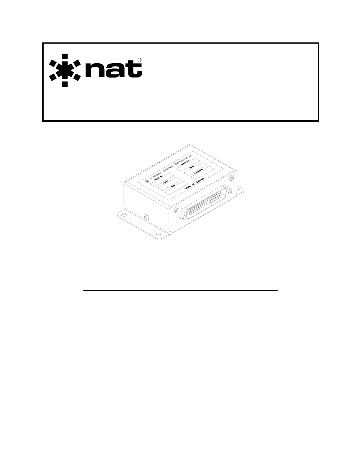
SM15
RS08
Remote Switch
INSTALLATION AND OPERATION MANUAL
REV 4.00 November 24, 2003
Northern Airborne Technology Ltd.
1925 Kirschner Road
Kelowna BC, Canada
V1Y 4N7
Telephone (250) 763-2232
Facsimile (250) 762-3374
Copyright 2003 by Northern Airborne Technology Ltd.
CONFIDENTIAL AND PROPRIETARY TO NORTHERN AIRBORNE TECHNOLOGY LTD.
Page 2

Page 3

SM15 Rev. 4.00 RS08 Remote Switch Manual
Performed at factory
Sections 1.0 through 3.0 of this Manual are
APPROVED by Transport Canada as
complying with the requirements of AWM511
for Appliance Type Certificate AP-11
Periodically NAT will release manual amendments. In order to maintain the most
accurate and up to date manual these amendments should be carried out immediately
upon receipt and recorded on the following amendment record.
AMENDMENT RECORD
Amendment
Number
Amendment
Date
Section(s)
Changed
Date
Entered
Entered By
1 Jan 18\05 2
Insert any Amendment Instruction sheets after this page.
Nov 24, 2003 Page ii
ENG-FORM: 820-0109.DOT
CONFIDENTIAL AND PROPRIETARY TO NORTHERN AIRBORNE TECHNOLOGY LTD.
Page 4

Page 5
INSTALL_OPS
MANUAL AMENDMENT
Manual: SM15 (RS08) Amendment #: 1
Document # SM15\RS08\Install_Ops\809-0001 Amendment Date: Jan 18, 2005
The purpose of this amendment is to add the Environmental Qualification Form (521-0)
to section 2.4 and to update section 2.3.2 Cable and Wiring statement paragraph 1.
Amendment Instructions:
1
2-1 to 2-3 Rev 4.00 2-1 to 2-3 Rev 4.00 Amendment #1
2
- RS08\001\521-0 Rev 1.00
Remove Drawings/Documents (Section 2) Replace or add Drawings/Documents (Section 2)
Note: Ensure that all drawings are inserted in the order shown on the latest drawing lists.
3 Update the Amendment Record sheet at the front of the manual.
4 Insert this page into the manual after the Amendment Record sheet (page ii).
Manual Amendment ends after the following amended pages
Remove Pages Replace With Pages
Amendment #1 Jan 18, 2005 Page 1
ENG-FORM: 809-0109.DOT
CONFIDENTIAL AND PROPRIETARY TO NORTHERN AIRBORNE TECHNOLOGY LTD.
Page 6

Page 7

SM15 Rev. 4.00 RS08 Remote Switch Manual
Table of Contents
Section Title Page
1.0 Description
1.1 Introduction 1-1
1.2 Purpose of Equipment 1-1
1.3 Features 1-1
1.4 Specifications 1-2
1.4.1 Electrical Specifications 1-2
1.4.2 Physical Specifications 1-2
1.4.3 Environmental Specifications 1-3
1.5 Unit Nomenclature 1-3
2.0 Installation
2.1 Introduction 2-1
2.2 Unpacking and Inspection 2-1
2.3 Installation Procedures 2-1
2.3.1 Warnings 2-1
2.3.2 Cabling and Wiring 2-1
2.3.3 External Switches and Lamps 2-2
2.3.4 Post-Installation Checks 2-2
2.4 Installation Drawings 2-3
3.0 Operation
3.1 Introduction 3-1
3.2 Mode Annunciation 3-1
3.3 NAV Selection 3-1
3.4 Annunciator Lighting 3-1
3.5 Fault Indications 3-1
3.5.1 Loss of Power 3-1
3.5.2 Failure Presentations 3-2
Nov 24, 2003 Page iii
ENG-FORM: 820-0109.DOT
CONFIDENTIAL AND PROPRIETARY TO NORTHERN AIRBORNE TECHNOLOGY LTD.
Page 8

Page 9

SM15 Rev. 4.00 RS08 Remote Switch Manual
Section 1.0 Description
1.1 Introduction
Information in this section consists of: purpose of equipment, features, specifications,
and a listing of all models available to the date of publication.
1.2 Purpose of Equipment
The RS08 is a bulkhead mounted remote switching unit. It is specifically designed to
handle the switching requirements of two navigation systems (i.e. NAV/GPS,
NAV1\NAV2) sharing a common NAV system indicator.
Switching control for the RS08 comes from an external switch, and provision is made to
force the return of the system to the VOR/ILS display, if an ILS station is selected by a
connected nav system.
The RS08 provides switching for FLAG, TO-FROM, and DEVIATION lines, as well as
providing annunciation output to show the display status of the common indicator.
1.3 Features
Dry circuit to 2A contacts are provided for 6 poles, and 2 poles are furnished crosslinked to provide positive functional annunciator drive, with a built-in lamp dimming
function (100 mA Max.) This provides the maximum possible safety margin for the pilot's
mode indicator.
Glideslope/ILS interlock is provided for indicator return to ILS mode, where allowed by
local Regulatory Authorities. Loss of power automatically returns the indicator to the
primary NAV aid. The RS08 Remote Switch operates from +9 to 33 Vdc without change
in interconnect.
All interconnect and relay contacts are gold plated. Relays are sealed, high vibration
rated (50g shock), dry nitrogen filled units. Circuit boards are constructed of G10-FR
(flame-retardant) material, with solder masks, reflowed tin plating, and environmental
post-coating.
Nov 24, 2003 Page 1-1
ENG-FORM: 800-0106.DOT
CONFIDENTIAL AND PROPRIETARY TO NORTHERN AIRBORNE TECHNOLOGY LTD.
Page 10

RS08 Remote Switch Manual SM15 Rev.4.00
1.4 Specifications
1.4.1 Electrical Specifications
Input Power +9 to 33 Vdc at 100 mA Max. (Excluding lamps).
Case is internally grounded.
Lamps Type 327/387 for 28 V (40 mA).
Type 330/382 for 14 V (80 mA).
Maximum lamp load is 100 mA if internal dimming
function is used.
Logic Ground seeking input for switch transfer.
Ground seeking ILS Enable input to return indicator to
ILS mode. Will accept positive bias on this line from
5-12 V, and an external diode or transistor junction in
series with the ground return.
Indicator Dry circuit switching to accommodate standard HSI
levels (500 µA), or up to 2 A @ 28 Vdc.
Flag bias 1.0 mA, if required.
Loads External 1 KΩ, if required.
Annunciators Lamp circuitry provided for mode annunciation.
Optional remote switch selectable dimming for 14/28V.
1.4.2 Physical Specifications
Height 1.25 inches (31.75 mm)
Depth 2.30 inches (58.42 mm) (excluding connector)
Width 4.50 inches (114.30 mm)
Mounting Bulkhead attachment (4 x 1032/AN3)
Weight 6 oz. (168 g) (excluding mating connector)
Page 1-2 Nov 24, 2003
ENG-FORM: 800-0106.DOT
CONFIDENTIAL AND PROPRIETARY TO NORTHERN AIRBORNE TECHNOLOGY LTD.
Page 11

SM15 Rev. 4.00 RS08 Remote Switch Manual
1.4.3 Environmental Specifications
Temperature -40 to +70°C (Ambient)
Altitude
RS08-001 25,000 ft. max.
RS08-350 35,000 ft. max.
RS08-500 50,000 ft. max.
Humidity 95% Non-Condensing
Shock 6g (all axes)
DO-160B Env. Cat:
RS08-001 /A1B1/BA/MNO/XXXXXXABBBBBB
RS08-350 /A1C1/BA/MNO/XXXXXXABBBBBB
RS08-500 /A1D1/BA/MNO/XXXXXXABBBBBB
1.5 Unit Nomenclature
The following list indicates the models available at the date of publication of this
document. Other models may be available.
Model Description / Distinction
RS08-001 Remote switch
Interlock and lamp dimmer (2 step)
Provides 6 poles of data transfer
Provides 2 poles of lamp transfer
14/28 Vdc operation
Gold contacts, sealed 50 g relays
Includes flag bias generator
Automatic ILS reversion circuit
Easily cascaded for more complex installations
RS08-350 Identical to RS08-001 but qualified to 35,000 feet
Suitable for mounting in unpressurized areas
RS08-500 Identical to RS08-001 but qualified to 50,000 feet
Suitable for mounting in unpressurized areas
End of Section 1.0
Nov 24, 2003 Page 1-3
ENG-FORM: 800-0106.DOT
CONFIDENTIAL AND PROPRIETARY TO NORTHERN AIRBORNE TECHNOLOGY LTD.
Page 12

Page 13

SM15 Rev.4.00 RS08 Remote Switch Manual
Section 2.0 Installation
2.1 Introduction
Information in this section consists of: unpacking and inspection procedures, installation
procedures, post-installation checks, and installation drawings.
2.2 Unpacking and Inspection
Unpack the equipment carefully and locate the warranty card. Inspect the unit visually
for damage due to shipping and report all such claims immediately to the carrier
involved. Note that each unit should have the following:
- RS08 Remote Switch
- Warranty Card
- Inspection Release
Verify that all items are present before proceeding and report any shortage immediately
to your supplier.
Complete the warranty card information and send it to NAT when the installation is
complete. If you fail to complete the warranty card, the warranty will be activated on
date of shipment from NAT.
2.3 Installation Procedures
2.3.1 Warnings
Do not bundle any lines from this unit with transmitter coax lines. Do not bundle any
logic or DC power lines from this unit with 400 Hz synchro wiring, or AC power lines.
In all installations, use shielded cable exactly as shown and ground as indicated.
Significant problems may result from not following these guidelines.
2.3.2 Cable and Wiring
All unshielded wire shall be selected in accordance with AC43.13-1B Change 1,
Paragraphs 11-76 through 11-78. Wire types should be to MIL-W-22759 as specified in
AC43.13-1B Change 1, Paragraphs 11-85, 11-86, and listed in Table 11-11. For
shielded wire applications, use Tefzel MIL-C-27500 shielded wire with solder sleeves
(for shield terminations) to make the most compact and easily terminated interconnect.
Follow the wiring diagrams in Section 2.6 as required.
Nov 24, 2003 Page 2-1
ENG-FORM: 805-0104.DOT Amendment #1 Jan 18, 2005
CONFIDENTIAL AND PROPRIETARY TO NORTHERN AIRBORNE TECHNOLOGY LTD.
Page 14

RS08 Remote Switch Manual SM15 Rev. 4.00
Allow 3 inches from the end of the wire to the shield termination to allow the hood to be
easily installed. Note that the hood is a "clamshell" hood and is installed after the wiring
is complete.
All wiring should be at least 24 AWG, except power and ground connections which
should be 20 AWG. Ensure that the ground connection is clean and well secured. To
prevent system failure or inadequate equipment protection, power to each component of
this system must be supplied from a separate breaker or fuse and not bundled to any
other source.
2.3.3 External Switches and Lamps
2.3.3.1 Transfer Switch
The transfer switch should be a positive action (SPST or SPDT) toggle or pushbutton
type, labeled as required. This switch is mandatory.
2.3.3.2 Lamp Dimmer Switch
The lamp dimmer switch should be a positive action, SPDT, toggle switch labeled DIM
on one side and BRIGHT on the other. This switch is not mandatory but is highly
recommended.
2.3.3.3 Lamp Test Switch
The lamp test switch should be a momentary action, DPDT, toggle or pushbutton switch
labeled LT TEST. This switch is not mandatory but is highly recommended.
2.3.3.4 Annunciators
Annunciators should be selected to suit the application. Note that a single switch/lamp
assembly can replace the transfer switch and annunciators. This should be a lighted
pushbutton switch (SPST/SPDT) with positive action (i.e., push on, push off), and two
legends to match the desired NAV functions. NAT P/N PB08-001 is recommended.
2.3.4 Post-Installation Checks
2.3.4.1 Voltage/resistance checks
Do not attach the RS08 until these conditions are met.
With the RS08 disconnected from its mating connector, check on pin 1 for +14/28 VDC
relative to ground and check pin 20 for continuity to ground (below 0.5 ohms).
Page 2-2 Nov 24, 2003
ENG-FORM: 805-0104.DOT Amendment #1 Jan 18, 2005
CONFIDENTIAL AND PROPRIETARY TO NORTHERN AIRBORNE TECHNOLOGY LTD.
Page 15

SM15 Rev.4.00 RS08 Remote Switch Manual
2.3.4.2 Power on checks
a) Power up the ship's systems with the RS08 installed, and check that the mode
annunciators transfer correctly with the appropriate switch selection. If the ‘ILS
Interlock’ is used in the installation, check that selecting the primary NAV system
to an ILS channel returns the display to the NAV/ILS mode, regardless of switch
setting.
b) Depending on the method selected for lamp dimming, ensure that operation
iscorrect (dimmer pot or switch) and that both lamps are fully functional. The
system cannot be accepted for service until all annunciations are correct.
c) Using a ramp test set or locally broadcast navigation signal, ensure that valid data
is presented on the shared indicator when in the primary NAV mode. To check,
turn off the secondary NAV receiver, and ensure that there is no interaction, or
cross-connected wiring. Switch the RS08 to the secondary NAV mode, and using
a ramp test set or locally broadcast navigation signal, ensure that the correct
presentation is provided on the shared indicator. To double check, rechannel or
turn off the primary NAV receiver, and ensure that there is no interaction or crossconnected wiring.
2.4 Installation Drawings
DRAWING REV. DESCRIPTION TYPE
RS08\001\302-0 1.01 Remote switch - Standard Configuration Block Diagram
RS08\001\403-0 1.03 Remote switch - Standard Configuration Interconnect
RS08\001\403-1 1.03 Remote switch - Installation Options Interconnect
RS08\001\403-2 1.03 Remote switch - Master/Slave Configuration Interconnect
RS08\001\405-0 1.01 Remote switch Connector Map
RS08\001\521-0 1.00 Remote switch Environmental Qual Form
RS08\001\903-0 1.03 Remote switch Isometric
RS08\001\922-0 1.02 Remote switch Mechanical
Section 2.0 ends after these Drawings
Nov 24, 2003 Page 2-3
ENG-FORM: 805-0104.DOT Amendment #1 Jan 18, 2005
CONFIDENTIAL AND PROPRIETARY TO NORTHERN AIRBORNE TECHNOLOGY LTD.
Page 16

Page 17

Confidential and Proprietary to NAT
Page 18

Page 19

Confidential and Proprietary to NAT
Page 20

Page 21

Confidential and Proprietary to NAT
Page 22

Page 23

Confidential and Proprietary to NAT
Page 24

Page 25

Confidential and Proprietary to NAT
Page 26

Page 27

Page 28

Page 29

Confidential and Proprietary to NAT
Page 30

Page 31

Confidential and Proprietary to NAT
Page 32

Page 33

SM15 Rev. 4.00 RS08 Remote Switch Manual
Section 3.0 Operation
3.1 Introduction
Information in this section consists of the functional and operating procedures for the
RS08 Remote Switch.
3.2 Mode Annunciation
A dual annunciator is provided for the pilot's reference, and indicates that the transfer
has been accomplished to the selected source. Provision is also made to allow
dimming of the annunciation by an external toggle switch. Because the ‘ILS Interlock’
can force a transfer of the system, the pilot should always take his cue from the
annunciators, not the transfer switch itself. If a lighted pushbutton switch with dual
legends is used, there will be no ambiguity.
3.3 NAV Selection
If at the time of installation, a NAV receiver was selected for connection to the ILS
interlock, and then is channeled to an ILS station, the RS08 will return the indicator to
the VOR/ILS mode irrespective of any other command. Care should be taken to not
preset any such station while navigating from the secondary NAV source or the
presentation will be switched back to the primary NAV system.
3.4 Annunciator Lighting
Since the annunciators must be readable in sunlight, power to these is not normally
taken from the aircraft lamp dimmer circuit, which would be off during daylight flying.
Instead, provision is made for a switched dimmer (full/half bright) control, to be mounted
by the annunciators. If a lamp test switch has been installed, it will light both lamps at
full brightness.
3.5 Fault Indications
3.5.1 Loss of Power
If power is lost to the RS08, both annunciators will be dark, and the system will return to
the VOR/ILS display. The lamps will NOT test OK. The pilot should confirm correct
data display by channeling the radio in question, or offsetting the radial, and checking
for the correct presentation.
Nov 24, 2003 Page 3-1
ENG-FORM: 809-0106.DOT
CONFIDENTIAL AND PROPRIETARY TO NORTHERN AIRBORNE TECHNOLOGY LTD.
Page 34

RS08 Remote Switch Manual SM15 Rev. 4.00
3.5.2 Failure Presentations
If there is an internal failure in the RS08 which causes loss of power to the relays, driver
or logic failure, it will appear as one of three presentations:
The annunciator stays lit in one mode or the other, and will not transfer.
The data will likely be correct, and can easily be confirmed by pilot test of the indicated
navigation system. Only one nav source will be available until the system is repaired.
This can also be caused by external switch failure.
No annunciator will light. Lamps test OK.
Indicates relay failure. Do not use any navigation data, as data is likely faulty. Repair
immediately.
Unit will transfer, but only one annunciator will light. Lamps test OK.
Indicates relay or wiring failure, and will probably give valid data only if the lamp lights in
the VOR/ILS mode. Confirm data by pilot test, and repair immediately.
In general, the pilot should always confirm that the presentation he sees is, in fact, tied
to the system he has selected. A simple radial offset or other method will greatly
improve operational safety, and insure that a power failure, ILS channeled nav or other
fault has not presented false navigation data on the HSI/CDI.
End of section 3.0
Page 3-2 Nov 24, 2003
ENG-FORM: 809-0106.DOT
CONFIDENTIAL AND PROPRIETARY TO NORTHERN AIRBORNE TECHNOLOGY LTD.
 Loading...