

Page 1
Installation and Operation Manual
RM01-001
Remote Memory
SM77
ISSUE 1.01
Northern Airborne Technology Ltd.
1925 Kirschner Road
Kelowna, BC, Canada.
V1Y 4N7
Telephone (250) 763-2232
Facsimile (250) 762-3374
Issued on the authority of Northern Airborne Technology Ltd.
Copyright 2009
Page 2
Page 3

RM01-001 Remote Memory
SM77 Installation and Operation Manual
Table of Contents
Section Title Page
1. Description
1.1 Introduction 1-1
1.2 Product Description 1-1
1.3 Design Features 1-1
1.4 Specifications 1-2
1.4.1 Electrical Specifications 1-2
1.4.2 Physical Specifications 1-2
1.4.3 Environmental Specifications 1-2
1.4.4 Product Approval 1-3
2. Installation
2.1 Introduction 2-1
2.2 Unpacking and Inspection 2-1
2.2.1 Warranty 2-1
2.3 Continued Airworthiness 2-1
2.4 Installation Procedures 2-1
2.4.1 Warnings 2-1
2.4.2 Cautions 2-2
2.4.3 Cabling and Wiring 2-2
2.4.4 Mounting 2-2
2.4.5 Post-Installation Checks 2-3
2.5 Adjustments and Connections 2-3
2.6 Accessories Required But Not Supplied 2-3
2.7 Installation Drawings 2-4
3. Operation
3.1 Introduction 3-1
3.2 General Information 3-1
Installation and Operation Manual Page iii
ENG-FORM: 820-0114.DOT
CONFIDENTIAL AND PROPRIETARY TO NORTHERN AIR BORNE TECHNOLOGY LTD.
Page 4

RM01-001 Remote Memory
SM77 Installation and Operation Manual
Section 1 Description
1.1 Introduction
Information in this section consists of product description, design features and specifications for the
RM01-001 Remote Memory (RM01). The RM01 has been developed for use in the Northern Airborne
Technology Ltd (NAT) Digital Audio Communication System (DACS) but can be used in other applications
as appropriate. All derivative product information shall be contained in the applicable manual
supplement, which may be obtained from Northern Airborne Technology Ltd as required.
Review all notes, warnings and cautions.
Note: This manual contains information applicable to units s/n 3000 and above. For information
applicable to units below s/n 3000 contact the product support department at Northern Airborne
Technology Ltd.
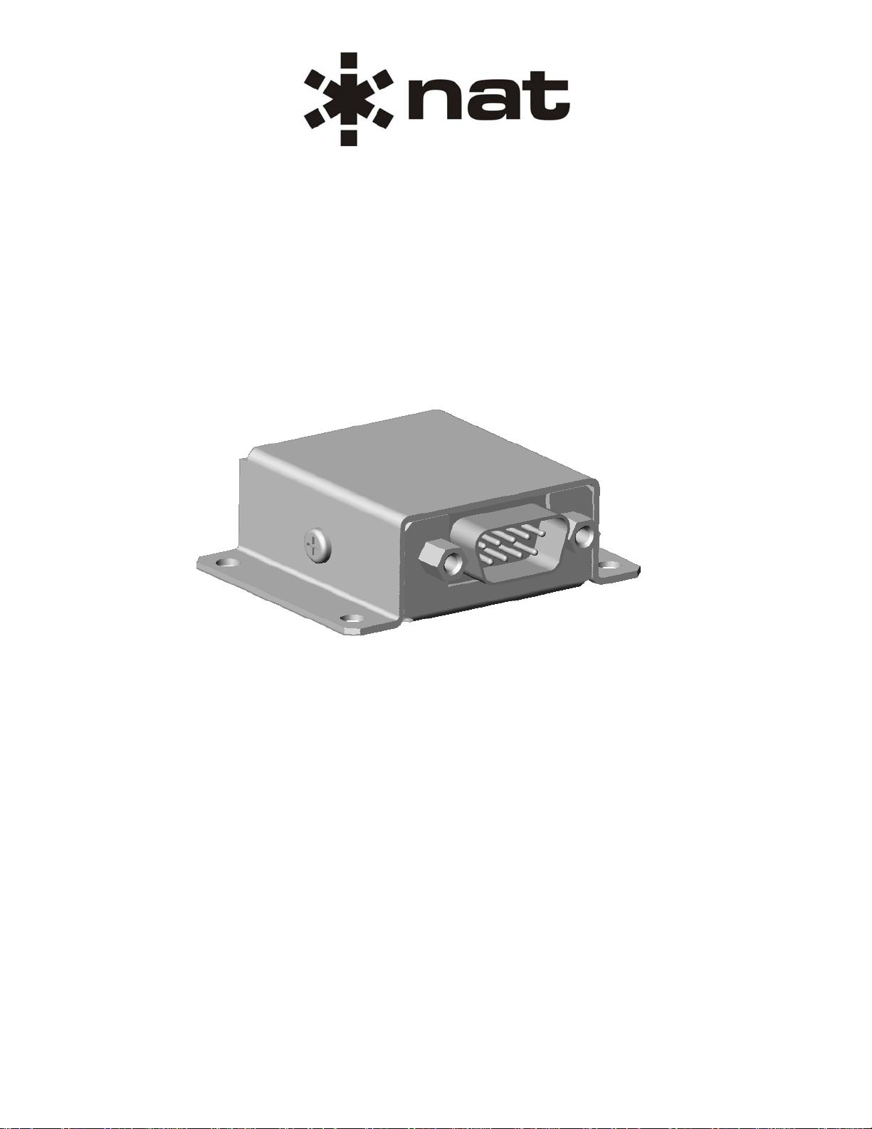
1.2 Product Description
The RM01 is a Remote Memory unit for the Northern Airborne Technology Ltd. (NAT) Digital Audio
Communication System (DACS).
The DACS is a communications management system that distributes and controls all of the audio in an
aircraft. It manages the audio from all transceivers, receivers and audio warning sources. It enables the
transmission of microphone audio to a selected transmitter and distributes all Inter-Communication
System (ICS) audio.
The RM01 is a remote mounted device that connects to the DACS AMU50 Audio Management Unit. The
RM01 stores the system’s configuration and aural alert files. Storing the system configuration and alert
files in this unit enables the replacement of the AMU50 without the need of downloading a new
configuration file.
The RM01 communicates with the AMU50 over a Serial Peripheral Interface (SPI) port. The RM01 also
receives regulated power from the AMU50.
1.3 Design Features
The RM01 provides digital memory accessible via a serial communications port to service an externally
attached device such as an Audio Management Unit. A Typical application of the RM01 would be to store
system configuration data or digital audio data.
The RM01 provides 64 Mbits of data storage capacity, which supports at least 120 seconds of 16 bit
digital audio data (32 kHz sampled).
Section 1 Rev: 1.01 Issue 1 Page 1-1
ENG-FORM: 800-0115.DOT
CONFIDENTIAL AND PROPRIETARY TO NORTHERN AIR BORNE TECHNOLOGY LTD.
Page 5

RM01-001 Remote Memory
SM77 Installation and Operation Manual
1.4 Specifications
1.4.1 Electrical Specifications
Input Signals
Input Operating Voltage
The RM01 requires a conditioned +5 Vdc power supply such as that provided by an
AMU50.
Nominal Operating Input Voltage 5.0 Vdc
Maximum Current: 0.1 A @ 5.0 Vdc
Communication
The RM01 communicates over a Serial Peripheral Interface (SPI) with an external device
such as an AMU50.
1.4.2 Physical Specifications
Height 18.4 mm (0.73 in) maximum
Depth 51.4 mm (2.03 in) maximum
Width 57.2 mm (2.25 in) maximum
Weight 0.04 kg (0.09 lbs) maximum
Material and Finish Brushed aluminium, conversion coated
Connectors One 9 pin D-sub (male), Jackpost locking hardware
Installation SPI Cable: 0.3 m (11.81 in) maximum
Installation Kit: RM01-IKC
Mounting Bulkhead Mount (four 6-32 screws)
1.4.3 Environmental Specifications
The RM01 has been tested to the environmental conditions listed below. Environmental categories for
which TSO compliance has been demonstrated are listed on the Environmental Qualification Form in
Section 2 of this manual.
Temperature -40 to +70° C (operating)
-45 and +85° C (short-time operating)
-55 to +85° C (ground survival)
Altitude 50,000 feet maximum
Humidity 95 % non-condensing
Shock Operational shock; 6 g for 11 ms
Crash safety (impulse); 20 g for 11 ms
Crash safety (sustained); 20 g for 3 s
Vibration RTCA/DO-160E Section 8 Categories (SBM) (U2FF1)
Section 1 Rev: 1.01 Issue 1 Page 1-2
ENG-FORM: 800-0115.DOT
CONFIDENTIAL AND PROPRIETARY TO NORTHERN AIR BORNE TECHNOLOGY LTD.
Page 6

SM77 Installation and Operation Manual
1.4.4 Product Approval
RM01-001 Remote Memory
1.4.4.1 FAA: TSO-C139
When installed as part of the Northern Airborne Technology Ltd DACS:
FAA: TSO-C139 (RTCA/DO-214 Class Ib, RTCA/DO-160E, RTCA/DO-178B Level C)
Refer to SM76 AMU50-001 Audio Management Unit Installation and Operation manual for further
installation compliance details.
1.4.4.2 EASA: ETSO-C50c
When installed as part of the Northern Airborne Technology Ltd DACS:
EASA: ETSO-C50c (RTCA/DO-214 Class Ib, RTCA/DO-160E, RTCA/DO-178B level C)
Refer to SM76 AMU50-001 Audio Management Unit Installation and Operation manual for further
installation compliance details.
Section 1 ends
Section 1 Rev: 1.01 Issue 1 Page 1-3
ENG-FORM: 800-0115.DOT
CONFIDENTIAL AND PROPRIETARY TO NORTHERN AIR BORNE TECHNOLOGY LTD.
Page 7

RM01-001 Remote Memory
SM77 Installation and Operation Manual
Section 2 Installation
2.1 Introduction
Information in this section consists of unpacking and inspection procedures, installation procedure s, po stinstallation checks and installation drawings for the RM01-001 Remote Memory (RM01).
Review all notes, warnings and cautions.
2.2 Unpacking and Inspection
Unpack the equipment carefully and locate the warranty card. Inspect the unit visually for damage due to
shipping and report all such claims immediately to the carrier involved. Check that all items listed below
are present before proceeding and report any shortage immediately to your supplier:
- Warranty Card
- Certificate of Conformity or Release Certification
2.2.1 Warranty
All Northern Airborne Technology Ltd. products are warranted for 2 years from date of installation by an
authorized NAT dealer, to be free of defects in workmanship or performance. This warranty covers all
materials and labour, but is exclusive of any transport to deliver the defective unit to and from NAT or its
designated warranty repair center, or any labour to remove or re-install the defective unit in the aircraft.
Contact NAT for any questions regarding this warranty, its applicability to your units and/or for return
authorization. NAT is the final arbitrator concerning warranty administration. Units which have been
physically damaged, burned, immersed in water or otherwise abused beyond the scope of normal use will
not be considered for warranty. WARRANTY IS VOID UNLESS THE PRODUCT IS INSTALLED BY AN
AUTHORIZED NAT DEALER. Product for which a warranty card is not returned shall be warranted from
date of manufacture.
2.3 Continued Airworthiness
Maintenance of the RM01 Remote Memory is ‘on condition’ only. Periodic maintenance of this product is
not required.
2.4 Installation Procedures
2.4.1 Warnings
Not Applicable.
Section 2 Rev: 1.00 Issue 1 Page 2-1
ENG-FORM: 805-0115.DOT
CONFIDENTIAL AND PROPRIETARY TO NORTHERN AIR BORNE TECHNOLOGY LTD.
Page 8

RM01-001 Remote Memory
SM77 Installation and Operation Manual
2.4.2 Cautions
CAUTION:
Do not bundle any lines from this unit with transmitter coax feed lines. Do not
bundle any logic, audio, or DC power lines from this unit with 400 Hz synchro
wiring or AC power lines. Do not position this unit next to any device with a
strong alternating magnetic field such as an inverter, motor or blower, or
significant audio interference will result.
In all installations, use shielded cable exactly as shown, and ground only as
indicated. Significant problems may result from not following these guidelines.
Failure to follow the installation and wiring instructions provided in this manual
for power and ground connections, including the rating of the circuit breaker,
may lead to damage in the power input circuitry of the unit.
2.4.3 Cabling and Wiring
All wire shall be selected in accordance with the original aircraft manufacturer's Maintenance Instructions
or AC43.13-1B Change 1, Paragraphs 11-76 through 11-78. Unshielded wire types shall qualify to
MIL-W-22759 as specified in AC43.13-1B Change 1, Paragraphs 11-85, 11-86, and listed in Table 11-11.
For shielded wire applications, use Tefzel MIL-C-27500 shielded wire with solde r sleeve s (fo r shield
terminations) to make the most compact and easily terminated interconnect. Follow the connector map in
Section 2.7 as required.
Allow 3" from the end of the shielded wiring to the shield termination to allow the connector hood to be
easily installed. Reference the interconnect drawing in Section 2.7 for shield termination details. Note that
the hood is a "clamshell" hood, and is installed after the wiring is complete.
Maintain wire segregation and route wiring in accordance with the original aircraft manufacturers
Maintenance Instructions.
Unless otherwise noted, all wiring shall be a minimum of 22 AWG. Refer to the interconnect drawing for
additional specifications. Check that the ground connection is clean and well secured, and that it shares
no path with any electrically noisy aircraft accessories such as blowers, turn and bank instruments or
similar loads.
2.4.4 Mounting
The RM01 can be bulkhead-mounted in any orientation, using four 6-32 screws. No shock or vibration
isolators are required.
The RM01 must be mounted to a clean metal surface which is electrically bonded to the aircraft ground
plane. The unit is finished with a coating that prevents corrosion. This coating is electrically conductive
and should not be removed for electrical bonding.
Section 2 Rev: 1.00 Issue 1 Page 2-2
ENG-FORM: 805-0115.DOT
CONFIDENTIAL AND PROPRIETARY TO NORTHERN AIR BORNE TECHNOLOGY LTD.
Page 9

RM01-001 Remote Memory
SM77 Installation and Operation Manual
2.4.5 Post-Installation Checks
2.4.5.1 Voltage/Resistance Checks
Do not attach the RM01 until the following conditions are met.
Install the AMU50 or similar audio management unit and check the following:
a) Check pin <6> for RM01 ground (ground return to AMU).
b) Check pin <5> for chassis ground (less than 0.5 Ω).
2.4.5.2 Power On Checks
Power up the aircraft’s systems.
a) Check pin <1> for RM01 power (5 Vdc from AMU).
Verify normal operation of all functions of the RM01. Refer to the Installation and Operation manual for
the device to which the RM01 is connected for verification of the RM01 operation.
Upon satisfactory completion of all performance checks, make all required log book entries, electrical
load, weight and balance amendments and other documentation as required by your local regulatory
agency before releasing the aircraft for service.
2.5 Adjustments and Connections
The RM01 stores system configuration data for an audio control system such as the DACS. When
installed in the DACS, the configuration data can be modified using the Device Configuration Software
(DevCs) application. Refer to the SM76 AMU50-001 Audio Management Unit Installation and Operation
Manual and the DevCs Installation and Operation manual for information on connection and operation of
the DevCs.
After an RM01 has been programmed using the DevCs, all settings that are essential to aircraf t operation
must be verified by a system test in both normal and emergency modes (e.g. direct audio audible to crew,
transmit and receive functions on COM1 and COM2 operate correctly for crew, required intercom
functions operate correctly, etc).
2.6 Accessories Required But Not Supplied
Installation kit p/n RM01-IKC is required to complete the installation. The kit consists of the following:
RM01-IKC consists of
Quantity Description NAT Part #
1 D-sub 9 Pin Socket Housing 20-21-009
9 Contact, Socket Crimp 20-26-901
1 Hood, D-sub, Metal 20-28-009
1 Cable Clamp, D-sub (SET) 20-27-189
Section 2 Rev: 1.00 Issue 1 Page 2-3
ENG-FORM: 805-0115.DOT
CONFIDENTIAL AND PROPRIETARY TO NORTHERN AIR BORNE TECHNOLOGY LTD.
Page 10

RM01-001 Remote Memory
SM77 Installation and Operation Manual
2.7 Installation Drawings
DRAWING REV. DESCRIPTION TYPE SERIAL No.
RM01\001\403-0 1.21 Remote Memory Interconnect 3000 and up
RM01\001\405-0 1.00 Remote Memory Connector Map 3000 and up
RM01\001\521-0 1.01 Remote Memory Environmental Qual. Form 3000 and up
RM01\001\922-0 1.10 Remote Memory Mechanical Installation 3000 and up
Section 2 ends following the above documents
Section 2 Rev: 1.00 Issue 1 Page 2-4
ENG-FORM: 805-0115.DOT
CONFIDENTIAL AND PROPRIETARY TO NORTHERN AIR BORNE TECHNOLOGY LTD.
Page 11

Page 12

Page 13

Page 14

Page 15

Page 16

Page 17

RM01-001 Remote Memory
SM77 Installation and Operation Manual
Section 3 Operation
3.1 Introduction
Information in this section consists of the functional and operational procedures for the RM01-001 Remote
Memory (RM01).
3.2 General Information
The RM01 is a Remote memory unit for the Northern Airborne Technology Ltd. (NAT) Digital Audio
Communication System (DACS).
The DACS is a communications management system that distributes and controls all of the audio in an
aircraft. It manages the audio from all transceivers, receivers and audio warning sources. It enables the
transmission of microphone audio to a selected transmitter and distributes all Inter-Communication
System (ICS) audio.
The RM01 is a remote mounted device that connects to the DACS AMU50 Audio Management Unit. The
RM01 stores the system’s configuration and aural alert files. Storing the system configuration and alert
files in this unit enables the replacement of the AMU50 without the need of downloading a new
configuration file.
The RM01 communicates with the AMU50 over a Serial Peripheral Interface (SPI) port. The RM01 also
receives regulated power from the AMU50.
Optionally, more than one RM01 may be used in an aircraft to provide rapid re-configuration of an aircraft
audio when an aircraft is assigned to a different role. The connector on the harness from the AMU50 can
be moved to the RM01 which contains the configuration appropriate to the required role.
The RM01 Remote Memory has no operator accessible controls.
Section 3 ends
Section 3 Rev: 1.00 Issue 1 Page 3-1
ENG-FORM: 806-0111.DOT
CONFIDENTIAL AND PROPRIETARY TO NORTHERN AIR BORNE TECHNOLOGY LTD.
 Loading...