

Page 1
Installation and Operation Manual
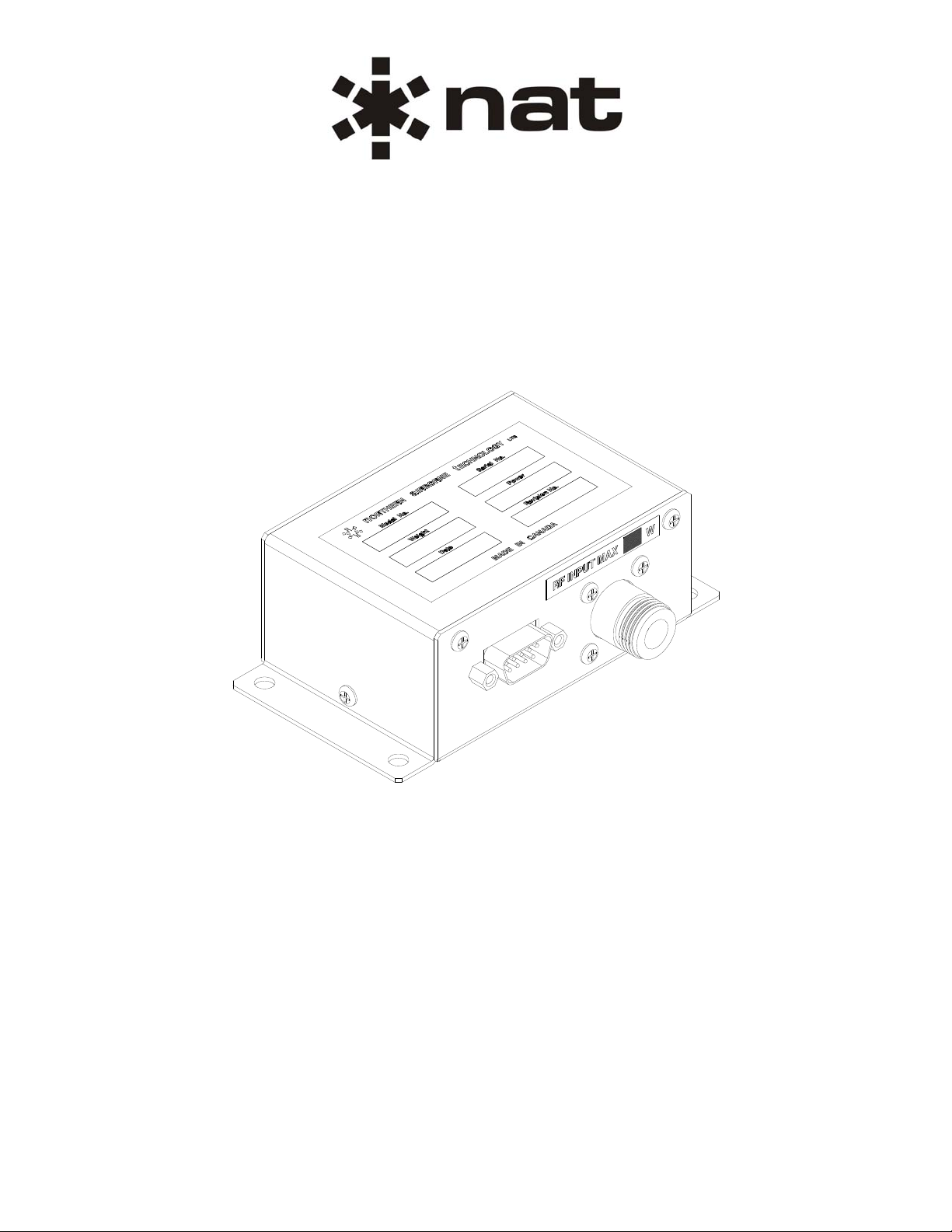
RA Series
Remote Attenuator
SM30
ISSUE 4.01
Northern Airborne Technology Ltd.
1925 Kirschner Road
Kelowna, BC, Canada.
V1Y 4N7
Telephone (250) 763-2232
Facsimile (250) 762-3374
Issued on the authority of Northern Airborne Technology Ltd.
Copyright 2003
Page 2
RA Series Remote Attenuator
SM30 Installation and Operation Manual
Prepared By: Checked By: Approved By:
The status of this installation and operation manual is controlled by issue shown on the title page. The
status of each section is controlled by revision shown in the footer of each page. All revisions affecting
sections of this manual have been incorporated into the latest issue.
ISSUE/REVISION RECORD
Manual Issue
Number
4.00 N/A N/A Nov 19, 2003
Section
Revision Number
Revision Description Issue Date
4.01 Section 1 Rev #: 1.00
Section 2 Rev #: 1.00
Revised manual using latest
templates.
Aug 6, 2008
Section 3 Rev #: 1.00
Installation and Operation Manual Page ii
ENG-FORM: 820-0114.DOT
CONFIDENTIAL AND PROPRIETARY TO NORTHERN AIR BORNE TECHNOLOGY LTD.
Page 3

RA Series Remote Attenuator
SM30 Installation and Operation Manual
Table of Contents
Section Title Page
1. Description
1.1 Introduction 1-1
1.2 Product Description 1-1
1.3 Design Features 1-1
1.4 Specifications 1-2
1.4.1 Electrical Specifications 1-2
1.4.2 RF Signal Specifications 1-2
1.4.3 Physical Specifications 1-2
1.4.4 Environmental Specifications 1-2
1.5 Unit Nomenclature 1-3
2. Installation
2.1 Introduction 2-1
2.2 Unpacking and Inspection 2-1
2.2.1 Warranty 2-1
2.3 Continued Airworthiness 2-1
2.4 Installation Procedures 2-1
2.4.1 Cabling and Wiring 2-1
2.4.2 Post-Installation Checks 2-2
2.5 Adjustments and Connections 2-2
2.6 Accessories Required But Not Supplied 2-3
2.7 Installation Drawings 2-3
3. Operation
3.1 Introduction 3-1
3.2 General Information 3-1
3.3 Controls and Indicators 3-1
3.4 Optional Features 3-1
3.5 Emergency Operation 3-1
Installation and Operation Manual Page iii
ENG-FORM: 820-0114.DOT
CONFIDENTIAL AND PROPRIETARY TO NORTHERN AIR BORNE TECHNOLOGY LTD.
Page 4

RA Series Remote Attenuator
SM30 Installation and Operation Manual
Section 1 Description
1.1 Introduction
Information in this section consists of product description, design features and specifications for the RA
Series Remote Attenuator. All derivative product information shall be contained in the applicable manual
supplement, which may be obtained from NAT as required.
Review all notes, warnings and cautions.
1.2 Product Description
The RA-series of remote attenuators reduce the RF transmit power from a transceiver under logic control
from a Tac/Com control head or a switch. The attenuator may also be enabled and perform the same
function during receive operations. The attenuator is normally enabled when the control line is unactuated
(not grounded). A ground (<1 Vdc) on the control line will bypass the attenuator and allow RF to pass at
full power. When enabled, the remote attenuator will reduce the incoming signal by a factor of 10
(RA10-xxx) to 1000 (RA30-xxx). There is a remote attenuator model that can handle up to 1 W
continuous power (RAxx-001) and another model that can handle up to 20 W continuous (RAxx-020).
The RA series Remote Attenuators are bulkhead mounted units specifically designed to allow attenuation
of aircraft radio transmissions. This is desirable under some conditions where the radio exceeds output
power limits of altitude. If the radios were simply adjusted to output the lower level, they may become
unstable and difficult to control tightly to the output tolerances. By installing a RA series Remote
Attenuator, radio operation is not impaired and the required output power is achieved.
RA units also normally attenuate the receive signals to reduce some channel interference from nearby
stations when at altitude.
1.3 Design Features
RA series Remote Attenuators are easy to install with an uncomplicated interconnect.
They are powered from a +28 Vdc aircraft supply and available in a variety of configurations.
A ground seeking keying circuit enables RF signals to pass eithe r attenuated or unattenuated.
All interconnect and relay contacts are gold plated. The relays are sealed, high vibration rated (50g
shock), dry nitrogen filled.
The circuit boards are constructed of G10-FR (flame retardant) material, with solder masks ref lowed tin
plating and environmentally post-coated.
Section 1 Rev: 1.00 Issue 4 Page 1-1
ENG-FORM: 800-0114.DOT
CONFIDENTIAL AND PROPRIETARY TO NORTHERN AIR BORNE TECHNOLOGY LTD.
Page 5

RA Series Remote Attenuator
SM30 Installation and Operation Manual
1.4 Specifications
1.4.1 Electrical Specifications
Input Power +20 to +33 Vdc at 160 mA max.
Case is internally grounded
Logic Ground seeking input for keyline capable of sinking 5 mA.
1.4.2 RF Signal Specifications
Frequency DC to 600 Mhz.
Insertion Loss 0.5 dB typical.
Attenuation
Keyed Less than 0.3 dB.
Unkeyed 10 – 30 dB nominal.
RF Power Input
-001 1 Watt continuous max.
-020 20 Watts continuous max.
1.4.3 Physical Specifications
RA10-001/RA30-001
Height 1.60" (41.0 mm) 1.60" (41.0 mm)
Length 4.60" (117.0 mm) 9.50" (241.0 mm)
Width 2.50" (64.0 mm) 2.50" (64.0 mm)
Weight 7.0 ounce s (210.0 g) 19.0 ounces (530.0 g)
Mounting Bulkhead Bulkhead
1.4.4 Environmental Specifications
Temperature -40 to +70° C
Altitude 16,500 feet max.
Humidity 95% Non-condensing
Shock 12g (any axis)
Vibration Conforms to DO-160B category ‘P’
RA10-020
Section 1 Rev: 1.00 Issue 4 Page 1-2
ENG-FORM: 800-0114.DOT
CONFIDENTIAL AND PROPRIETARY TO NORTHERN AIR BORNE TECHNOLOGY LTD.
Page 6

RA Series Remote Attenuator
SM30 Installation and Operation Manual
1.5 Unit Nomenclature
The Remote Attenuators are defined by two groups of numbers. The first set identifies the degree of
attenuation and the second identifies the maximum RF input power.
RA10-001 Í Identifies maximum RF Input Power
Ï
Identifies attenuation in dB
The models currently available are as follows:
RA10-001 10 dB attenuation with 1 W RF input power max.
RA10-020 10 dB attenuation with 20 W RF input power max.
RA30-001 30 dB attenuation with 1 W RF input power max.
Section 1 ends
Section 1 Rev: 1.00 Issue 4 Page 1-3
ENG-FORM: 800-0114.DOT
CONFIDENTIAL AND PROPRIETARY TO NORTHERN AIR BORNE TECHNOLOGY LTD.
Page 7

RA Series Remote Attenuator
SM30 Installation and Operation Manual
Section 2 Installation
2.1 Introduction
Information in this section consists of unpacking and inspection procedures, installation procedure s, po stinstallation checks and installation drawings for the RA Series Remote Attenuator.
Review all notes, warnings and cautions.
2.2 Unpacking and Inspection
Unpack the equipment carefully and locate the warranty card. Inspect the unit visually for damage due to
shipping and report all such claims immediately to the carrier involved. Check that all items listed below
are present before proceeding and report any shortage immediately to your supplier:
- Warranty Card
- Certificate of Conformity or Release Certification
2.2.1 Warranty
All Northern Airborne Technology Ltd. products are warranted for 2 years from date of installation by an
authorized NAT dealer, to be free of defects in workmanship or performance. This warranty covers all
materials and labour, but is exclusive of any transport to deliver the defective unit to and from NAT or its
designated warranty repair center, or any labour to remove or re-install the defective unit in the aircraft.
Contact NAT for any questions regarding this warranty, its applicability to your units and/or for return
authorization. NAT is the final arbitrator concerning warranty administration. Units which have been
physically damaged, burned, immersed in water or otherwise abused beyond the scope of normal use will
not be considered for warranty. WARRANTY IS VOID UNLESS THE PRODUCT IS INSTALLED BY AN
AUTHORIZED NAT DEALER. Product for which a warranty card is not returned shall be warranted from
date of manufacture.
2.3 Continued Airworthiness
Maintenance of the RA Series Remote Attenuator is ‘on condition’ only. Periodic maintenance of this
product is not required.
2.4 Installation Procedures
2.4.1 Cabling and Wiring
All wire shall be selected in accordance with the original aircraft manufacturer's Maintenance Instructions
or AC43.13-1B Change 1, Paragraphs 11-76 through 11-78. Unshielded wire types shall qualify to
MIL-W-22759 as specified in AC43.13-1B Change 1, Paragraphs 11-85, 11-86, and listed in Table 11-11.
For shielded wire applications, use Tefzel MIL-C-27500 shielded wire with solde r sleeve s (fo r shield
terminations) to make the most compact and easily terminated interconnect. Follow the connector map in
Section 2.7 as required.
Section 2 Rev: 1.00 Issue 4 Page 2-1
ENG-FORM: 805-0117.DOT
CONFIDENTIAL AND PROPRIETARY TO NORTHERN AIR BORNE TECHNOLOGY LTD.
Page 8

RA Series Remote Attenuator
SM30 Installation and Operation Manual
Coaxial cable shall be selected in accordance with MIL-C-17 unless otherwise specified. Do not use coax
cable with PVC insulation. Teflon dielectric cable is encouraged at or above VHF frequencies or where
cable runs exceed 8 feet. Note that at VHF frequencies, cables losses due to long cable runs and tight
bends may reduce the ERP (Effective Radiated Power) by greater than 50%.
Allow 3" from the end of the shielded wiring to the shield termination to allow the connector hood to be
easily installed. Reference the interconnect drawing in Section 2.7 for shield termination details. Note that
the hood is a "clamshell" hood, and is installed after the wiring is complete. Aircraft harnessing shall
permit the unit to be lowered from the panel for easy access to all side adjustments. Do NOT mount the
unit until all adjustments have been performed.
Maintain wire segregation and route wiring in accordance with the original aircraft manufacturers
Maintenance Instructions. Coaxial cables shall be routed separately from existing wire bundle s in the
aircraft to minimize electromagnetic coupling effects.
Unless otherwise noted, all wiring shall be a minimum of 24 AWG, except power and ground lines, which
shall be a minimum of 22 AWG. Reference the Interconnect drawing for additional specifications. Check
that the ground connection is clean and well secured, and that it shares no path with any electrically noisy
aircraft accessories such as blowers, turn and bank instruments or similar loads. Power to this unit must
be supplied from a separate circuit breaker or fuse (fast blow), and not attached to any other circuit
breaker without additional protection. Verify that the selected circuit breaker size and wire gauge are
adequate for the installation using the techniques specified in AC43.13-1B Change 1, Paragraphs 11-47
through 11-51 and 11-66 through 11-69.
2.4.2 Post-Installation Checks
2.4.2.1 Voltage/Resistance Checks
Do not attach the RA Series Remote Attenuator until the following conditions are met.
Check the following:
a) Check J103 pin 2, 6 and 7 for continuity to ground (less than 0.5Ω).
b) Check J103 pin 1 for +28 Vdc relative to ground.
2.4.2.2 Power On Checks
Power up the aircraft’s systems and confirm normal operation of all functions of the RA Series Remote
Atenuator. Refer to Section 3 (Operation) for specific operational details.
a) Confirm correct radio operation, both receive and transmit.
Upon satisfactory completion of all performance checks, make all required log book entries, electrical
load, weight and balance amendments and other documentation as required by your local regulatory
agency before releasing the aircraft for service.
2.5 Adjustments and Connections
There are no adjustments for this product.
Section 2 Rev: 1.00 Issue 4 Page 2-2
ENG-FORM: 805-0117.DOT
CONFIDENTIAL AND PROPRIETARY TO NORTHERN AIR BORNE TECHNOLOGY LTD.
Page 9

RA Series Remote Attenuator
SM30 Installation and Operation Manual
2.6 Accessories Required But Not Supplied
There are no accessories for this product.
2.7 Installation Drawings
DOCUMENT REV. DESCRIPTION TYPE
RA10
RA10\405-0 1.00 Remote Attenuator Connector Map
RA10-001
001\922-0 1.00 Remote Attenuator Mechanical Installation
RA10-020
020\403-0 1.00 Remote Attenuator Interconnect
020\922-0 1.00 Remote Attenuator Mechanical Installation
NT136-PAS
NT136-PAS\403-0 1.21 RA10-020 with NT136-PAS
NT450-EUR
NT450-EUR\403-0 1.11 RA10-001 with NT450-EUR
Interconnect
Transceiver Installation.
Interconnect
Transceiver Installation.
Section 2 ends following the above documents
Section 2 Rev: 1.00 Issue 4 Page 2-3
ENG-FORM: 805-0117.DOT
CONFIDENTIAL AND PROPRIETARY TO NORTHERN AIR BORNE TECHNOLOGY LTD.
Page 10

Page 11

Page 12

Page 13

Page 14

Page 15

Page 16

RA Series Remote Attenuator
SM30 Installation and Operation Manual
Section 3 Operation
3.1 Introduction
Information in this section consists of functional and operational procedures for the RA Series Remote
Attenuator.
3.2 General Information
The operation of the RA Series Remote Attenuator is generally as part of a NAT system including a
Tac/Com control head and aircraft radio. In normal use, the only operational considerations involve
correctly installing the unit and ensuring the attenuator control line is correctly installed to a compatible
operating system. After that is completed, the operation is completely transparent to the user.
3.3 Controls and Indicators
The RA Series Remote Attenuator is controlled by grounding the antenna control line. When the antenna
control line is grounded, the RF signal is not attenuated. When the antenna control line is floating, the RF
signal is attenuated. There are no indicators for this product.
3.4 Optional Features
There are no optional features for this product.
3.5 Emergency Operation
There is no emergency mode of operation for this product.
Section 3 ends
Section 3 Rev: 1.00 Issue 4 Page 3-1
ENG-FORM: 806-0112.DOT
CONFIDENTIAL AND PROPRIETARY TO NORTHERN AIR BORNE TECHNOLOGY LTD.
 Loading...