

Page 1
Installation and Operation Manual
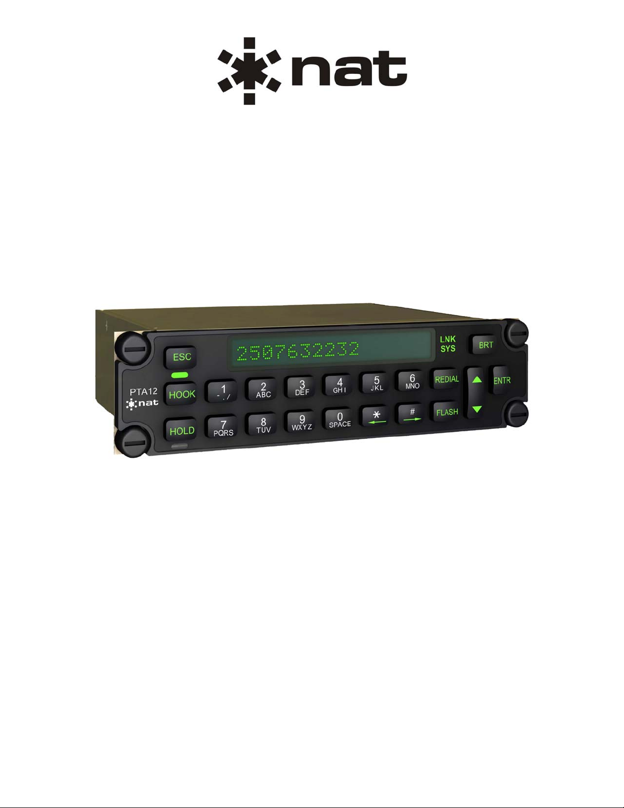
PTA12-100
POTS Telephone Adapter
with Display
SM55-2
ISSUE 4.02
Northern Airborne Technology Ltd.
1925 Kirschner Road
Kelowna, BC, Canada.
V1Y 4N7
Telephone (250) 763-2232
Facsimile (250) 762-3374
Issued on the authority of Northern Airborne Technology Ltd.
Copyright 2004
Page 2
Page 3

PTA12-100 POTS Telephone Adapter with Display
SM55-2 Installation and Operation Manual
Table of Contents
Section Title Page
1. Description
1.1 Introduction 1-1
1.2 Product Description 1-1
1.3 Design Features 1-1
1.4 Specifications 1-2
1.4.1 Electrical Specifications 1-2
1.4.2 Physical Specifications 1-5
1.4.3 Environmental Specifications 1-6
2. Installation
2.1 Introduction 2-1
2.2 Unpacking and Inspection 2-1
2.2.1 Warranty 2-1
2.3 Continued Airworthiness 2-1
2.4 Installation Procedures 2-2
2.4.1 Warnings 2-2
2.4.2 Cautions 2-2
2.4.3 Cabling and Wiring 2-2
2.4.4 Post-Installation Checks 2-2
2.5 Adjustments and Connections 2-3
2.6 Accessories Required But Not Supplied 2-4
2.7 Installation Drawings 2-4
3. Operation
3.1 Introduction 3-1
3.2 General Information 3-1
3.3 Controls and Indicators 3-2
3.3.1 Display 3-2
3.3.2 Keypad Controls 3-2
3.3.3 Annunciators 3-4
3.4 Name / Number Storage and Display 3-5
3.5 Modes of Operation 3-5
3.5.1 Call Mode 3-5
3.5.2 Recall Mode 3-6
3.5.3 Edit Mode 3-6
3.6 Keypad Function Tables 3-8
Installation and Operation Manual Page iii
ENG-FORM: 820-0115.DOT
CONFIDENTIAL AND PROPRIETARY TO NORTHERN AIRBORNE TECHNOLOGY LTD.
Page 4

PTA12-100 POTS Telephone Adapter with Display
SM55-2 Installation and Operation Manual
Section 1 Description
1.1 Introduction
Information in this section consists of product description, design features and specifications for the
PTA12-100 POTS Telephone Adapter with Display. All derivative product information shall be contained
in the applicable manual supplement, which may be obtained from NAT as required.
Review all notes, warnings and cautions.
1.2 Product Description
The PTA12-100 POTS Telephone Adapter is a keypad control and display unit for airborne telephone
system applications. The PTA12-100 connects to a telephone system transceiver by a two-wire POTS
(Plain Old Telephone Service) interface. The PTA12-100 can be connected to the aircraft audio
controller(s) or directly to an aviation headset/handset.
Note: The PTA12-100 is designed to meet standard North American PSTN requirements, but it is not
recommended or approved for landline applications.
1.3 Design Features
The PTA12-100 POTS Telephone Adapter is a compact Dzus mounted POTS telephone interface with a
keypad and display. Many of the PTA12-100 functions are controlled by a microcontroller.
The functions of the PTA12-100 include: speech audio circuits, hook switch, ring indication, flash, hold,
redial, serial data communications, backlighting, display, speed dial, Globalstar™ satcom status, DTMF
tone generation and ringer audio generate. The speech audio circuits include a mic input amplifier and a
phones output amplifier with front panel volume control.
Hook switch control and indication is provided on the front panel. The hook switch may be controlled and
its status viewed from a location remote to the PTA12-100 front panel. Ring indication is also provided on
the front panel with a flashing green LED. A flash key is provided on the front panel to interrupt the hook.
A hold key on the front panel mutes all audio to and from the headset and is indicated by a green LED. A
redial key on the front panel automatically redials the last number called.
A two-wire POTS port achieves the interface to the satcom system transceiver. A serial port allows for
data communications to satcom systems.
The front panel keypad has backlighting provided.
The display is an LED dot matrix character display with brightness control.
Speed dial allows numbers to be stored and recalled from memory.
Indication of Globalstar™ satcom signal strength and system availability status is provided by LED lit
dead-front text on the front panel.
Section 1 Rev: 1.00 Issue 4 Page 1-1
ENG-FORM: 800-0114.DOT
CONFIDENTIAL AND PROPRIETARY TO NORTHERN AIR BORNE TECHNOLOGY LTD.
Page 5

PTA12-100 POTS Telephone Adapter with Display
SM55-2 Installation and Operation Manual
1.4 Specifications
1.4.1 Electrical Specifications
Power Supply
Input Voltage
Normal Operation +30.3 Vdc (maximum)
+27.5 Vdc (nominal)
+22.0 Vdc (minimum)
+18.0 Vdc (emergency)
Abnormal Operation +32.2 Vdc (maximum)
+27.5 Vdc (nominal)
+20.5 Vdc (minimum)
Input Current 0.2 Amps max. @ +27.5 Vdc
Lighting
1.0 mA max. @ +5.0 Vdc
Input Signals
Microphone 250 mVrms rated input level, amplified dynamic
Key In Used to remotely control the Hook function. Momentarily pull to
Output Signals
Rated Level 20 dBm ±3 dB into 600 or 150 Ohms @ 100mW
Circuitry Type Differential
Frequency Response ≤3 dB roll-off from 350 Hz to 3 kHz
Distortion ≤5% THD @ rated power output
Audio Noise ≤ -50 dB from rated output (no signal)
Power Input Voltage with reverse, over voltage and over current
protection
1.0 mA max. @ +27.5 Vdc
Impedance 150 Ohm ±10%
Circuitry Type Single Ended
Mic Bias +13 ±0.5 Vdc (selectable via switch)
Power Ground for a period greater than 500 ms to activate the
Hook function. Momentarily open circuit or apply voltage greater
than 26 Vdc for a period greater than 500 ms to set the Hook to
inactive. Optically isolated and requires 10 mA max source
current.
Section 1 Rev: 1.00 Issue 4 Page 1-2
ENG-FORM: 800-0114.DOT
CONFIDENTIAL AND PROPRIETARY TO NORTHERN AIR BORNE TECHNOLOGY LTD.
Page 6

PTA12-100 POTS Telephone Adapter with Display
SM55-2 Installation and Operation Manual
Available Audio RX audio, Sidetone, DTMF sidetone
Ringing tone (enabled or disabled externally)
RX Audio See RX Audio in the Bidirectional Signals section for rated output
level
Sidetone Rated mic input yields rated phones output with rated TX mic
audio set on TIP/RING and both front panel VOL control and S/T
level potentiometer set to max.
DTMF Sidetone -9 dBm ±3 dB into 600 Ohms
Ringer Audio 14 dBm ±2 dB into 600 Ohms with ringer audio enabled on the
Phones Output (RGR internal switch set to DOWN) and
2.5 Vrms setup on the Ringer Audio Output
Ringer Drive Pulled to Power Ground when ringer is active (based on ringing
cadence)
Open collector, 250mA max sink current @ +28 Vdc
Over-current and over-voltage protected
Key Out When Key In is wired for Hook latching or is tied to Power
Ground, this output is pulled to Power Ground when the Hook
Switch is active
Solid state relay output, optically isolated, 100mA max sink
current @ +28 Vdc
Bidirectional Signals
POTS (2 wire) Polarity insensitive and current limited
On-hook Condition
DC Voltage withstands ±70 Vdc max.
Resistance 10M to 15M Ohms
Ringing Condition
Impedance 10k to 15k Ohms @ 25 Hz
Active when ringing signal on tip/ring >30 Vrms @ 25 Hz
Inactive when ringing signal on tip/ring <10 Vrms @ 25 Hz
Accepts square or sinusoidal ringing functions
Withstands 120 Vrms (max), 25 Hz sinusoidal ringing function
Off-hook Condition
Impedance 600 Ohms @ 1kHz (nominal)
Circuitry Type Balanced
DC Loop Current 25 mA (typical) to 130 mA (max)
Section 1 Rev: 1.00 Issue 4 Page 1-3
ENG-FORM: 800-0114.DOT
CONFIDENTIAL AND PROPRIETARY TO NORTHERN AIR BORNE TECHNOLOGY LTD.
Page 7

PTA12-100 POTS Telephone Adapter with Display
SM55-2 Installation and Operation Manual
DC Voltage ≤9.0 Vdc @ 25 mA loop current
Frequency Response ≤3 dB roll-off from 350 Hz to 3 kHz
Distortion ≤5% THD
Audio Noise ≤ -50 dB from rated output (no signal)
Available Audio TX Audio, RX Audio
TX Audio -1 dBm ±1dB into 600 Ohms with <5% THD
(Mic Input to tip/ring) (test condition: 250 mVrms @ 1kHz into Mic input, Mic level
potentiometer set to max.)
RX Audio -20 to 0 dBm
(Typical expected 400 mVrms @ 1kHz RX audio on TIP/RING yields rated phones
audio level) output with both front panel VOL control and RX level
potentiometer set to max.
DTMF Signalling Standard DTMF frequencies used
Frequency Tolerance ±1.5%
Supported Codes 0 – 9, *, #
DTMF TX on tip/ring -2.2 dBm ±1.0 dB into 600 Ohms (DTMF level potentiometer set
to max.)
Serial Port RS232 protocol, RX, TX and GND
Baud Rate 19200
Frame Size 8 bits
Parity none
Stop Bits 1
Flow Control Not available
Annunciators
LNK and SYS, green LED with dead-front text
HK (Hook Status / Ringer Active)
HK and HLD, green LED without dead-front text
On Hook LED off
Off Hook LED on
Ringer On LED flashes (0.33 second period @ 50% duty cycle)
Section 1 Rev: 1.00 Issue 4 Page 1-4
ENG-FORM: 800-0114.DOT
CONFIDENTIAL AND PROPRIETARY TO NORTHERN AIR BORNE TECHNOLOGY LTD.
Page 8

PTA12-100 POTS Telephone Adapter with Display
SM55-2 Installation and Operation Manual
HLD (Hold Status)
On Hold LED on
Off Hold LED off
LNK (satcom link)
Link Established LED on
Link Down LED off
SYS (satcom system)
Available for Voice LED on
Busy LED off
1.4.2 Physical Specifications
Height 1.52" (38.6 mm)
Depth 4.17" (105.9 mm) max. behind panel
Width 5.77" (146.6 mm) in front of panel
4.82" (122.4 mm) behind panel
Weight 0.80 lbs (0.36 kg)
Mounting Dzus Mounting (four fasteners)
Front Panel Aluminum with polycarbonate label and elastomeric keypad
Display 16 5x7 pixel characters with green polarized filter
Material/Finish Chassis & cover are 5052-H32 brushed aluminum with chromate
Connectors One male filtered 25 pin D-submin with Positronics V5 locking
Silicone rubber, tactile push-buttons backlit by amber LEDs
Front panel bezel is not backlit
conversion finish
tabs
Section 1 Rev: 1.00 Issue 4 Page 1-5
ENG-FORM: 800-0114.DOT
CONFIDENTIAL AND PROPRIETARY TO NORTHERN AIR BORNE TECHNOLOGY LTD.
Page 9

PTA12-100 POTS Telephone Adapter with Display
SM55-2 Installation and Operation Manual
1.4.3 Environmental Specifications
Temperature -20 to +55°C (operating)
-55 to +85°C (survival)
Altitude 50,000 feet max.
Humidity > 95%
Vibration DO-160D Cat. [(SBM)(UF)]
Qualification of the PTA12-100 POTS Telephone Adapter with Display was completed in accordance with
DO-160D Env. Cat. A1/D1-BAB[(SBM)(UF)]XXXXXXZBABB[UUX]MXXXX.
Note: Tested to DO-160D pre-change 1 and 2.
Section 1 ends
Section 1 Rev: 1.00 Issue 4 Page 1-6
ENG-FORM: 800-0114.DOT
CONFIDENTIAL AND PROPRIETARY TO NORTHERN AIR BORNE TECHNOLOGY LTD.
Page 10

PTA12-100 POTS Telephone Adapter with Display
SM55-2 Installation and Operation Manual
Section 2 Installation
2.1 Introduction
Information in this section consists of unpacking and inspection procedures, installation procedures, postinstallation checks and installation drawings for the PTA12-100 POTS Telephone Adapter with Display.
Review all notes, warnings and cautions.
2.2 Unpacking and Inspection
Unpack the equipment carefully and locate the warranty card. Inspect the unit visually for damage due to
shipping and report all such claims immediately to the carrier involved. Check that all items listed below
are present before proceeding and report any shortage immediately to your supplier:
- Warranty Card
- Operators Manual
- Certificate of Conformity or Release Certification
2.2.1 Warranty
All Northern Airborne Technology Ltd. products are warranted for 2 years from date of installation by an
authorized Northern Airborne Technology Ltd. dealer, to be free of defects in workmanship or
performance. This warranty covers all materials and labour, but is exclusive of any transport to deliver the
defective unit to and from Northern Airborne Technology Ltd. or its designated warranty repair center, or
any labour to remove or re-install the defective unit in the aircraft. Contact Northern Airborne Technology
Ltd. for any questions regarding this warranty, its applicability to your units and/or for return authorization.
Northern Airborne Technology Ltd. is the final arbitrator concerning warranty administration. Units which
have been physically damaged, burned, immersed in water or otherwise abused beyond the scope of
normal use will not be considered for warranty. WARRANTY IS VOID UNLESS THE PRODUCT IS
INSTALLED BY AN AUTHORIZED NORTHERN AIRBORNE TECHNOLOGY LTD. DEALER. Product
for which a warranty card is not returned shall be warranted from date of manufacture.
2.3 Continued Airworthiness
Maintenance of the PTA12-100 POTS Telephone Adapter with Display is ‘on condition’ only. Periodic
maintenance of this product is not required.
Section 2 Rev: 1.01 Issue 4 Page 2-1
ENG-FORM: 805-0121.DOT
CONFIDENTIAL AND PROPRIETARY TO NORTHERN AIRBORNE TECHNOLOGY LTD.
Page 11

PTA12-100 POTS Telephone Adapter with Display
SM55-2 Installation and Operation Manual
2.4 Installation Procedures
2.4.1 Warnings
High volume settings can cause hearing damage.
Set the headset volume control to the minimum volume setting prior to conducting
tests, and slowly increase the headset volume to a comfortable listening level.
2.4.2 Cautions
Do not take a ground from the instrument panel or similar location that shares a ground
return with a turn and bank, horizon or other motor driven instrument. This may cause the
PTA12-100 unit to pick up the sound of the motor as ground loop interference..
WARNING:
CAUTION:
2.4.3 Cabling and Wiring
All wire shall be selected in accordance with the original aircraft manufacturer's Maintenance Instructions
or AC43.13-1B Change 1, Paragraphs 11-76 through 11-78. Unshielded wire types shall qualify to
MIL-W-22759 as specified in AC43.13-1B Change 1, Paragraphs 11-85, 11-86, and listed in Table 11-11.
For shielded wire applications, use Tefzel MIL-C-27500 shielded wire with solder sleeves (for shield
terminations) to make the most compact and easily terminated interconnect. Follow the connector map in
Section 2.7 as required.
Allow 3" from the end of the shielded wiring to the shield termination to allow the connector hood to be
easily installed. Reference the interconnect drawing in Section 2.7 for shield termination details.
Maintain wire segregation and route wiring in accordance with the original aircraft manufacturers
Maintenance Instructions.
Unless otherwise noted, all wiring shall be a minimum of 22 AWG, except power and ground lines, which
shall be a minimum of 20 AWG. Reference the Interconnect drawing for additional specifications. Check
that the ground connection is clean and well secured, and that it shares no path with any electrically noisy
aircraft accessories such as blowers, turn and bank instruments or similar loads.
2.4.4 Post-Installation Checks
2.4.4.1 Voltage/Resistance Checks
Do not attach the PTA12-100 until the following conditions are met.
Check the following:
a) Check P101, pins <1> and <3> for +28 Vdc relative to ground.
b) Check P101, pins <14>, <16> and <19> for continuity to ground (less than 0.5Ω).
Section 2 Rev: 1.01 Issue 4 Page 2-2
ENG-FORM: 805-0121.DOT
CONFIDENTIAL AND PROPRIETARY TO NORTHERN AIRBORNE TECHNOLOGY LTD.
Page 12

(
[up]
PTA12-100 POTS Telephone Adapter with Display
SM55-2 Installation and Operation Manual
2.4.4.2 Power On Checks
Notes: 1. PTA12-100 functionality is highly dependant on the airborne telephone system interface.
Check proper operation of the telephone transceiver, and check that the transceiver has
an activated telephone line.
2. Where the PTA12-100 is connected to an existing audio system, check that the PTA12-100
is properly selected when performing audio checks.
Power up the aircraft’s systems and confirm normal operation of all functions of the PTA12-100. Refer to
Section 3 (Operation) for specific operational details.
a) Initiate a call to a valid telephone number and verify the operation for HOOK, HOLD, DTMF
keys (0 – 9, *, #) and VOL. Re-initiate the call using REDIAL. Test the FLASH function (where
applicable) while in the off-hook state (active).
b) Place the PTA12-100 in the on-hook (inactive) state, and have another party call the line
connected to the PTA12. Confirm proper RINGER, HOOK and HOLD operation.
c) To verify proper operation, all functions and levels shall be checked in-flight.
Upon satisfactory completion of all performance checks, make all required log book entries, electrical
load, weight and balance amendments and other documentation as required by your local regulatory
agency before releasing the aircraft for service.
2.5 Adjustments and Connections
The following adjustments are accessible through holes in the side of the unit shown in Figure 1.
Rotating the trimpots cw will increase the level of the related output and ccw
will decrease it.
Internal Trimpot Adjustments
LTS adjusts keypad backlighting level from min to max
DTMF adjusts DTMF level on POTS interface
S/T adjusts sidetone level
RX adjusts receive level on phones output
MIC adjusts mic level on POTS interface
RGR adjusts ringer level on both ringer audio and phones output
Internal Switch Settings
RGR on [down] ringer audio available on both phones
(ringer select) and ringer audio outputs
off [up] ringer audio only available on ringer audio
output
FLA / FLB select FLA flash = 90 ms ±40 ms
(hook flash) select FLB flash = 600 ms ±100 ms
MIC on [down] mic bias supplied by PTA12
mic bias) off
mic bias not supplied
Figure 1: Adjustments
Section 2 Rev: 1.01 Issue 4 Page 2-3
ENG-FORM: 805-0121.DOT
CONFIDENTIAL AND PROPRIETARY TO NORTHERN AIRBORNE TECHNOLOGY LTD.
Page 13

PTA12-100 POTS Telephone Adapter with Display
SM55-2 Installation and Operation Manual
2.6 Accessories Required But Not Supplied
Installation kit p/n D25SV-IKC (crimp) is required to complete the installation. The kit consists of the
following:
Quantity Description NAT Part No.
1 D-min 25 Socket Housing 20-21-025
25 MS Crimp Socket 20-26-901
1 25 Pin JVL Hood/Locklever 20-29-250
2.7 Installation Drawings
DOCUMENT REV. DESCRIPTION TYPE
PTA12-100
PTA12\100\403-0 1.11 POTS Telephone Adapter with Display Interconnect
PTA12\100\403-1 1.11 POTS Telephone Adapter with Display Interconnect
PTA12\100\403-2 1.11 POTS Telephone Adapter with Display Interconnect
PTA12\100\403-3 1.11 POTS Telephone Adapter with Display Interconnect
PTA12\100\403-4 1.11 POTS Telephone Adapter with Display Interconnect
PTA12\100\405-0 1.01 POTS Telephone Adapter with Display Connector Map
PTA12\100\905-0 1.00 POTS Telephone Adapter with Display Faceplate
PTA12\100\922-0 1.10 POTS Telephone Adapter with Display Mechanical Installation
STX100-000
STX100\000\403-6 1.00 STX100 GLOBALSTAR™ Satphone Receiver Interconnect
STX100\000\403-7 1.00 STX100 GLOBALSTAR™ Satphone Receiver Interconnect
Section 2 ends following the above documents
Section 2 Rev: 1.01 Issue 4 Page 2-4
ENG-FORM: 805-0121.DOT
CONFIDENTIAL AND PROPRIETARY TO NORTHERN AIRBORNE TECHNOLOGY LTD.
Page 14

Page 15

Page 16

Page 17

Page 18

Page 19

Page 20

Page 21

Page 22

Page 23

Page 24

PTA12-100 POTS Telephone Adapter with Display
SM55-2 Installation and Operation Manual
Section 3 Operation
3.1 Introduction
Information in this section consists of functional and operational procedures for the PTA12-100 POTS
Telephone Adapter with Display.
3.2 General Information
The PTA12-100 POTS Telephone Adapter is a keypad control and display unit for airborne telephone
system applications. The PTA12-100 connects to a telephone system transceiver by a two-wire POTS
(Plain Old Telephone Service) interface. The PTA12-100 can be connected to the aircraft audio
controller(s) or directly to an aviation headset/handset.
Note: The PTA12-100 is designed to meet standard North American PSTN requirements, but it is not
recommended or approved for landline applications.
The PTA12-100 POTS Telephone Adapter is a compact Dzus mounted POTS telephone interface with a
keypad and display. Many of the PTA12-100 functions are controlled by a microcontroller.
The functions of the PTA12-100 include: speech audio circuits, hook switch, ring indication, flash, hold,
redial, serial data communications, backlighting, display, speed dial, Globalstar™ satcom status, DTMF
tone generation and ringer audio generate. The speech audio circuits include a mic input amplifier and a
phones output amplifier with front panel volume control.
Hook switch control and indication is provided on the front panel. The hook switch may be controlled and
its status viewed from a location remote to the PTA12-100 front panel. Ring indication is also provided on
the front panel with a flashing green LED. A FLASH button is provided on the front panel to interrupt the
hook. A HOLD button on the front panel mutes all audio to and from the headset and is indicated by a
green LED. A REDIAL button on the front panel automatically redials the last number called.
The interface to the satcom system transceiver is achieved by a two-wire POTS port. A serial port allows
for data communications to satcom systems.
The front panel keypad has backlighting provided. The display is an LED dot matrix character display with
brightness control.
Speed dial allows numbers to be stored and recalled from memory.
Indication of Globalstar™ satcom signal strength and system availability status is provided by LED lit
dead-front text on the front panel.
Section 3 Rev: 1.00 Issue 4 Page 3-1
ENG-FORM: 806-0112.DOT
CONFIDENTIAL AND PROPRIETARY TO NORTHERN AIR BORNE TECHNOLOGY LTD.
Page 25

PTA12-100 POTS Telephone Adapter with Display
SM55-2 Installation and Operation Manual
3.3 Controls and Indicators
3.3.1 Display
The PTA12-100 has a 16-character LED display, with each character block consisting of a 5x7 pixel
matrix as shown in Figure 1. Display features depend on the status of the unit and are described in the
relevant sections.
Brightness = 5
Figure 1: Front View
3.3.1.1 Display Brightness
The front panel BRT button controls display brightness. Each time the BRT button is pressed, the display
brightness increases by one step. In Default Power-Up mode only, the display will show the current
brightness level (1 through 8) until the next operator action. Once the maximum brightness (8) is reached
the brightness level wraps around to the lowest setting (1).
The display is dimmed to half brightness upon activation of the front panel backlighting.
3.3.2 Keypad Controls
The keypad controls are silicone rubber tactile push-buttons backlit by amber LEDs, and are used to
manage all the operator functions of the PTA12.
3.3.2.1 Number and Symbol Buttons
The number (0 through 9) and symbol (*, #) buttons on the keypad have different uses depending on the
selected mode. Full information will be given in the relevant sections and in the keypad function table in
Section 3.6.
3.3.2.2 HOOK
The HOOK button is pressed to initiate or receive a call. This corresponds to lifting the handset of a
telephone ‘off the hook’. Each time the HOOK button is pressed, the hook switch toggles on / off.
The ‘hook status / ringer active’ annunciator is a green LED above the HOOK button. The LED is off when
the unit is inactive (‘on-hook’) and will illuminate continuously when the unit is active (‘off-hook’). If the unit
is inactive (‘on-hook’), this LED also acts as a ‘Ringer Active’ annunciator by flashing when an incoming
Section 3 Rev: 1.00 Issue 4 Page 3-2
ENG-FORM: 806-0112.DOT
CONFIDENTIAL AND PROPRIETARY TO NORTHERN AIR BORNE TECHNOLOGY LTD.
Page 26

PTA12-100 POTS Telephone Adapter with Display
SM55-2 Installation and Operation Manual
call activates the audible ringing tone on the Ringer Audio output, or in the headset, depending on the
installation setting. If the unit is already in use (‘off-hook’), the new caller will generally hear a ‘busy’ signal
(depending on the telephone system transceiver used).
Note: The Ringing Detect circuit that activates the headset ringer, the Ringer Audio output and the
flashing LED also sends a signal to a further discrete output for a remote indicator (light bulb,
etc.) if required.
The hook switch may also be controlled by an external input. The HOOK button on the PTA12-100 front
panel has master control of the hook switch control. When the PTA12-100 is configured for remote hook
control and PTA12-100 has been selected by an audio panel TX selector, pressing the PTT for at least
0.5 second will active the hook switch (like pressing and releasing the HOOK button). The hook switch
may be released by deselecting the PTA12-100 on the audio panel.
The PTA12-100 may be configured to indicate hook status remotely. In this configuration, an external
annunciation device may be used to indicate the status of the PTA12-100 hook switch. This is a discrete
output that follows the hook status.
3.3.2.3 HOLD
The HOLD button allows the operator to put a call ‘on hold’ by muting the microphone and phones audio.
This feature is only available when the unit is active (‘off-hook’).
The hold status annunciator is a green LED below the HOLD button. The LED illuminates to indicate that
a call is on hold, and switches off when the call audio is returned to active status.
3.3.2.4 FLASH
The FLASH button is typically used in a system where ‘call waiting’ and ‘call transfer’ are supported.
When the unit is active (‘off-hook’), the FLASH button is used to interrupt a call and allow the user to
respond to a second call. This feature is only available when the unit is active (‘off-hook’) or in Call mode.
3.3.2.5 REDIAL
The REDIAL button recalls and dials the last number dialed (up to 16 digits). This is the number dialed
between an off-hook and on-hook cycle. This is non-volatile storage, i.e.: the last dialed number is ‘stored’
when the unit is powered down.
Pressing REDIAL in Call mode recalls the last number dialed, shows it on the display and dials it
immediately.
If the unit is in Default Power-Up mode when the REDIAL button is pressed, the last number dialed is
shown on the display. To dial this number, first press the HOOK button to confirm a dial tone is present
and then press the ENTR button to send the DTMF tone on the two-wire interface.
Note: If there are no numbers in the redial buffer, the screen will display Empty! and no number will be
dialed.
Section 3 Rev: 1.00 Issue 4 Page 3-3
ENG-FORM: 806-0112.DOT
CONFIDENTIAL AND PROPRIETARY TO NORTHERN AIR BORNE TECHNOLOGY LTD.
Page 27

PTA12-100 POTS Telephone Adapter with Display
SM55-2 Installation and Operation Manual
3.3.2.6 Phones Volume (▲▼)
The UP/DOWN arrow button is a momentary digital rocker switch used to increase and decrease the
phones output volume when the PTA12-100 is in Call mode (i.e. the hook switch is active), or when the
hook switch is inactive but the Ringer Detect circuit is active.
The phones output volume increases by pressing the ▲ (up) arrow button and decreases with the ▼
(down) arrow button. There are a total of 32 steps from minimum volume to maximum volume and with
each ▲ or ▼ press, the display indicates the volume level (1 through 32). The display will show Volume
Up or Volume Dn (with the relevant volume level at the right of the display) until the next operator action.
The UP/DOWN arrow button may be used to adjust the phones volume by one step at a time by pressing
and releasing the button within one second. The level may also be used to auto-advance by holding down
either UP or DOWN for more than one second. In auto-advance mode the volume steps at approximately
five levels per second. Once at the top of the volume range (level 32) the control remains at 32 and does
not wrap around to level 1. The same is true for the bottom of the range (level 1). Once at level 1
subsequent presses of the DOWN arrow does not change the level.
The last value of the phones volume is stored in non-volatile memory, and is retained upon power down.
3.3.3 Annunciators
3.3.3.1 HOOK and HOLD Annunci ators
The HOOK and HOLD buttons have associated annunciators (see Sections 3.3.2.2 and 3.3.3.3).
3.3.3.2 Satcom Annunciators
The other two annunciators, LNK and SYS, are immediately to the right of the display and are green LED
'dead-front' text annunciators. This means that they are not visible until they are illuminated.
These annunciators are only operational when the PTA12-100 is interfaced to an STX100 satcom data
communications port.
3.3.3.3 LNK (Satcom Link)
The LNK text will not be visible (LED off) if the satcom link is down and will illuminate green (LED on)
when the satcom link is established.
3.3.3.4 SYS (Satcom System)
The SYS text will not be visible (LED off) if the satcom system is busy and will illuminate green (LED on)
when the satcom system is available for voice.
Section 3 Rev: 1.00 Issue 4 Page 3-4
ENG-FORM: 806-0112.DOT
CONFIDENTIAL AND PROPRIETARY TO NORTHERN AIR BORNE TECHNOLOGY LTD.
Page 28

PTA12-100 POTS Telephone Adapter with Display
SM55-2 Installation and Operation Manual
3.4 Name / Number Storage and Display
The PTA12-100 can store up to 16 sets of data, each consisting of two lines: the first line has an identifier
(address number) followed by a name and the second line is the associated telephone number.
Each name line starts with the two-digit address number (01 through 16) followed by a colon and has up
to 13 character spaces available to store the alphanumeric name. There are up to 16 character spaces
for the phone number. The display only shows name or number information at one time. In Recall mode,
pressing the ← (#) or → (½) buttons will toggle from name to number or number to name. Full information
on storing and editing information is provided in Section 3.5.3.
Note: The # and * buttons may not be used in either the name or number since these buttons are used
as ← and → when the PTA12-100 is in edit mode.
3.5 Modes of Operation
Upon initialization, the PTA12-100 is in a Default Power-Up mode and the display will show PTA12-100
X.XX.X, where x.xx.x is the firmware revision number. The unit will automatically enter this mode at power
up, or when reset. From Default mode, 3 different modes of operation may be selected: Call mode, Recall
mode or Edit mode (see Sections 3.5.1 through 3.5.3).
3.5.1 Call Mode
The PTA12-100 is put in Call mode by pressing the HOOK button. The green hook LED will illuminate,
the display will show Call Mode (if entered from Default Power-Up mode) and the keypad can then be
used just like a telephone to dial numbers.
3.5.1.1 Making a Call in Call Mode
In Call mode (hook switch active) the number (0 through 9) and symbol (½, #) buttons on the keypad are
used to ‘dial’ the required telephone number by generating the corresponding DTMF tone on the POTS
output. The digit that has been pressed is shown on the display and the corresponding DTMF tone is sent
immediately. The whole number is retained on the display for visual confirmation that the correct number
has been dialed. Pressing the HOOK button again terminates the call, turns off the green hook LED, and
returns the unit to Default mode.
As each button is pressed, audible confirmation is provided on the sidetone of the headset output.
For a summary of button functions available in Call mode refer to Table 2 in Section 3.6.
3.5.1.2 Receiving a call
The hook LED will flash to signal an incoming call. To answer, press the HOOK button (putting the unit
into Call mode). The hook LED will then illuminate steady green until the call is terminated by pressing the
HOOK button again.
Section 3 Rev: 1.00 Issue 4 Page 3-5
ENG-FORM: 806-0112.DOT
CONFIDENTIAL AND PROPRIETARY TO NORTHERN AIR BORNE TECHNOLOGY LTD.
Page 29

PTA12-100 POTS Telephone Adapter with Display
SM55-2 Installation and Operation Manual
3.5.2 Recall Mode
This mode is entered from Default mode by either buttoning in a valid number address (01 through 16) as
described in Section 3.4, or by pressing the up/down arrow button.
Note: Unlike Edit or Call modes, there is no message on the display to advise that the unit is in Recall
mode.
In Recall mode, numbers are retrieved from memory and displayed. The up/down arrow button (▲▼)
scrolls through the list of all 16 addresses, whether they are blank or filled. The address name is
displayed by default, but if the address name is blank, the corresponding number will be displayed.
The ← or → button toggles between name and number.
The up/down arrow button (▲▼) is used to scroll through the list. If the up arrow button (▲) is pressed
first, the display scrolls from position 01 upwards until the top of the list is reached. At the top of the list
the scroll wraps around to the lowest address. The down arrow button (▼) scrolls downwards from
position 16 to the lowest number (01) and then wraps around to the top of the list.
3.5.2.1 Making a Call in Recall Mode
The display will show each stored name or number as it is selected (either by scrolling or direct address
selection). When the desired name/number is found and shown on the display, press the HOOK button.
The unit enters Call mode and the hook LED will illuminate green. When a dial tone is heard, press the
ENTR button to dial the phone number. In Call mode the HOLD and FLASH functions are available for
use. To terminate a call, press the HOOK button again. The unit will exit call mode and the hook LED will
go out.
Note: In Recall mode, the ESC button may be used to cancel the current activity and return to Default
mode.
3.5.3 Edit Mode
From Default mode, press the ENTR button to select Edit mode. An Edit Mode message is displayed for
approximately 2 – 3 seconds and then a message is displayed on how to continue: ↑ ↓ or Address. It is
not necessary to wait for this message before continuing.
If the up/down arrow button (▲▼) is pressed, the complete list of addresses scrolls up or down. This is
identical to scrolling operation in Recall mode. In Edit mode, if an address number is keyed, the
corresponding address number and name will be displayed without the need for scrolling; for example if
the 0 button followed by the 1 button is pressed, the contents of location 01 are displayed.
Each name line starts with a two-digit address number (01 through 16) followed by a colon and has 13
character spaces available to store the alphanumeric name. There are 16 character spaces for the phone
number. Any character shown on buttons 0 through 9 may be used to store a name. The relevant button
is pressed until the required character is displayed and the ← or → buttons are used to move to the
previous or next character if required; for example if the relevant letters are both on the same button. The
phone number can consist of up to 16 digits, in numerical form only and each entered number will
automatically index on to the next space. The display only shows name or number information at one
time. Pressing the ← or → buttons will toggle from name to number or number to name.
Section 3 Rev: 1.00 Issue 4 Page 3-6
ENG-FORM: 806-0112.DOT
CONFIDENTIAL AND PROPRIETARY TO NORTHERN AIR BORNE TECHNOLOGY LTD.
Page 30

PTA12-100 POTS Telephone Adapter with Display
SM55-2 Installation and Operation Manual
3.5.3.1 Keypad Functions in Edit Mode
In Edit mode (hook switch inactive) the keypad buttons do not provide DTMF tones. In Edit mode the
lower text portion of these buttons is also implemented. This means that characters 0 through 9,
A through Z, -, ., / and space are displayed when the corresponding button is pressed. The desired
character for each button is displayed by pressing the key button. Each key press will scroll through the
viewable characters for the corresponding button pressed. The → and ← buttons provide horizontal
cursor movement in Edit mode. The up/down arrow button (▲▼) provides number scrolling in Recall and
Edit modes and provides phones volume adjustment in Call mode. For a summary of the front panel
button functions available in Edit and Call mode see Table 2 in Section 3.6.
3.5.3.2 Editing or Entering Address Information
If there is nothing stored in the selected address Empty! will be displayed and pressing the ENTR button
will bring up the prompt Enter Name. Using the keypad, characters are entered using the 0 through 9
buttons and edited using the ← and → buttons. When entering name information, alphanumeric
characters are available and are selected by pressing the appropriate button. The alpha characters are
displayed first and then the numbers. For the button marked 2ABC, the display order will be A, then B,
then C, then 2 and will then wraps around to A again. Each time a different button is pressed, the cursor
automatically advances by one position. If it is necessary to use the same button for two adjacent
characters, the right arrow must be used to advance the cursor. See Table 1 in Section 3.6 for a complete
button summary for Edit mode.
After the name has been entered, press the ENTR button to move to the next part of the address and the
prompt Enter Number is displayed. Only numbers are available and are entered using the 0 through 9
buttons and edited using ← and → buttons. Each key press (except 0) will automatically advance the
cursor by one position even if the same number is entered several times. The zero (0) button is also used
to enter spaces. Pressing this button displays first 0, then space and then wraps around back to 0 again.
When using the 0 button, any combination of adjacent zeroes and/or spaces will necessitate using the
arrow button to advance the cursor.
To store the name and number into memory after the number has been entered, the ENTR button must
be pressed. The completion message Stored! is then displayed to indicate that the address has been
stored, and the unit returns to Edit mode.
To cancel all editing done to the selected address, press the ESC button instead of the ENTR button and
the unit will return to Default mode.
If the selected address has stored data, the address name is displayed. If the ENTR button is pressed,
the message Del ← or Edit → is displayed. If the current address is to be deleted, press the ← button,
and to edit press the → button. If edit is selected, the name is displayed and editing is allowed. The ←
button is then used to select the character(s) to be edited. Press the ENTR button to accept and store any
changes, or the ESC button to cancel the edit activity. After the name and number have been stored, the
message Stored! is displayed to indicate the completion of editing and the unit returns to Edit mode.
Note: If information is stored in the address line but no corresponding phone number is entered (or vice
versa), the Empty! message will still be displayed when scrolling through the relevant lines even
though there may be information in the other part of the address.
If delete is selected instead of edit, ENTR To Delete is displayed to confirm the delete operation. If the
ESC button is pressed, the delete is canceled and the unit returns to Default mode. If the ENTR button is
Section 3 Rev: 1.00 Issue 4 Page 3-7
ENG-FORM: 806-0112.DOT
CONFIDENTIAL AND PROPRIETARY TO NORTHERN AIR BORNE TECHNOLOGY LTD.
Page 31

PTA12-100 POTS Telephone Adapter with Display
SM55-2 Installation and Operation Manual
pressed, the selected address data from both lines is deleted (cleared) and the completion message
Deleted! is displayed. The unit then returns to Edit mode.
The ESC button may be used at any time to cancel the current operation. Pressing the ESC button from
Edit mode returns the unit to Default Power-Up mode.
3.6 Keypad Function Tables
The PTA12-100 keypad buttons function differently depending on the current mode of the unit. A brief
outline of the differences is given below as a quick reference guide. Table 1 shows Default and Recall
modes and Table 2 shows Call and Edit modes.
Button Default Power-Up Mode Function Recall Mode Function
0 – 9
* No function
# No function
ESC Cancels current button activity Default mode is entered
HOOK Call mode is entered (hook switch is toggled to active)
HOLD No function No function
REDIAL
FLASH No function No function
UP Puts the PTA12-100 into Recall mode.
DOWN Puts the PTA12-100 into Recall mode.
BRT
ENTR Puts the PTA12-100 into Edit mode. No function
Number buttons are used only to enter address
locations 01 through 16. This puts the PTA12-100 into
Recall mode.
Retrieves the last number dialed and displays it. (To
send the number, press HOOK and then ENTR)
Increases display brightness and wraps around from
max to min brightness. Brightness level is displayed.
Table 1
Default and Recall Modes
Number buttons are used only to
enter address locations 01 through
16.
← available to toggle display
Only
between name and number
→ available to toggle display
Only
between name and number
Call mode is entered (hook switch is
toggled to active)
No function
Scrolls up through the list of stored
numbers
Scrolls down through the list of
stored numbers
Increases display brightness and
wraps around from max to min
brightness
Section 3 Rev: 1.00 Issue 4 Page 3-8
ENG-FORM: 806-0112.DOT
CONFIDENTIAL AND PROPRIETARY TO NORTHERN AIR BORNE TECHNOLOGY LTD.
Page 32

PTA12-100 POTS Telephone Adapter with Display
SM55-2 Installation and Operation Manual
Button Call Mode Function Edit Mode Function
1 DTMF tone 1 transmitted and digit 1 displayed 1, -, ., or / displayed
2 DTMF tone 2 transmitted and digit 2 displayed 2, A, B or C displayed
3 DTMF tone 3 transmitted and digit 3 displayed 3, D, E or F displayed
4 DTMF tone 4 transmitted and digit 4 displayed 4, G, H or I displayed
5 DTMF tone 5 transmitted and digit 5 displayed 5, J, K or L displayed
6 DTMF tone 6 transmitted and digit 6 displayed 6, M, N or O displayed
7 DTMF tone 7 transmitted and digit 7 displayed 7, P, Q, R or S displayed
8 DTMF tone 8 transmitted and digit 8 displayed 8, T, U or V displayed
9 DTMF tone 9 transmitted and digit 9 displayed 9, W, X, Y or Z displayed
0 DTMF tone 0 transmitted and digit 0 displayed 0 or character space displayed
*
# DTMF tone # transmitted and char # displayed
ESC No function
HOOK
HOLD Mutes mic and phones No function
REDIAL
FLASH
UP Increases the phones volume
DOWN Decreases the phones volume
BRT
ENTR
DTMF tone
Toggles the hook switch to inactive, and enters
Default mode
Retrieves the last number dialed, displays it, and
calls the number
Takes hook switch inactive for selected flash
pulse duration
Increases display brightness and wraps around
from max to min brightness
Sends a number dialed from Default or Recall
mode
½ transmitted and char * displayed
Table 2
Call and Edit Modes
Section 3 ends
Only ← available (moves cursor 1 position
to left or selects delete data of a selected
address)
Only → available (moves cursor 1 position
to right or selects edit data of a selected
address)
Cancels current activity during store and
returns to Default mode
Activates the hook switch and enters Call
mode
No function
No function
Scrolls up through the list of stored
numbers
Scrolls down through the list of stored
numbers
Increases display brightness and wraps
around from max to min brightness
Accepts a data item or completes a
sequence.
Section 3 Rev: 1.00 Issue 4 Page 3-9
ENG-FORM: 806-0112.DOT
CONFIDENTIAL AND PROPRIETARY TO NORTHERN AIR BORNE TECHNOLOGY LTD.
 Loading...