

Page 1
Part of
SM15
PB08
Illuminated Pushbutton Switch
INSTALLATION AND OPERATION MANUAL
REV 4.00 November 24, 2003
Northern Airborne Technology Ltd.
1925 Kirschner Road
Kelowna BC, Canada
V1Y 4N7
Telephone (250) 763-2232
Facsimile (250) 762-3374
Copyright 2003 by Northern Airborne Technology
CONFIDENTIAL AND PROPRIETARY TO NORTHERN AIRBORNE TECHNOLOGY LTD.
Page 2

Page 3

SM15 Rev 4.00 PB08 Illuminated Pushbutton Switch Manual
Periodically NAT will release manual amendments. In order to maintain the most
accurate and up to date manual these amendments should be carried out immediately
upon receipt and recorded on the following amendment record.
AMENDMENT RECORD
Amendment
Number
Amendment
Date
Section(s)
Changed
Date
Entered
Entered By
Insert any Amendment Instruction sheets after this page.
Nov 24, 2003 Page ii
ENG-FORM: 820-0109.DOT
CONFIDENTIAL AND PROPRIETARY TO NORTHERN AIRBORNE TECHNOLOGY LTD.
Page 4

Page 5

SM15 Rev 4.00 PB08 Illuminated Pushbutton Switch Manual
Table of Contents
Section Title Page
1.0 Description
1.1 Introduction 1-1
1.2 Purpose of Equipment 1-1
1.3 Features 1-1
1.4 Specifications 1-1
1.4.1 Electrical Specifications 1-1
1.4.2 Physical Specifications 1-1
1.5 Unit Nomenclature 1-2
2.0 Installation
2.1 General 2-1
2.2 Unpacking and Inspection 2-1
2.3 Installation Procedures 2-1
2.3.1 Warnings 2-1
2.3.2 Cautions 2-1
2.3.3 Notes 2-2
2.3.4 Installing the Legends 2-2
2.3.5 Changing Lamps 2-2
2.4 Installation Drawings 2-2
3.0 Operation
3.1 Introduction 3-1
3.2 Performance 3-1
3.2.1 Switch Operation 3-1
3.2.2 Lamp Operation 3-1
Nov 24, 2003 Page iii
ENG-FORM: 820-0109.DOT
CONFIDENTIAL AND PROPRIETARY TO NORTHERN AIRBORNE TECHNOLOGY LTD.
Page 6

Page 7

SM15 Rev. 4.00 PB08 Illuminated Pushbutton Switch Manual
Section 1.0 Description
1.1 Introduction
Information in this section consists of: purpose of equipment, features, specifications,
and a listing of all models available to the date of publication.
1.2 Purpose of Equipment
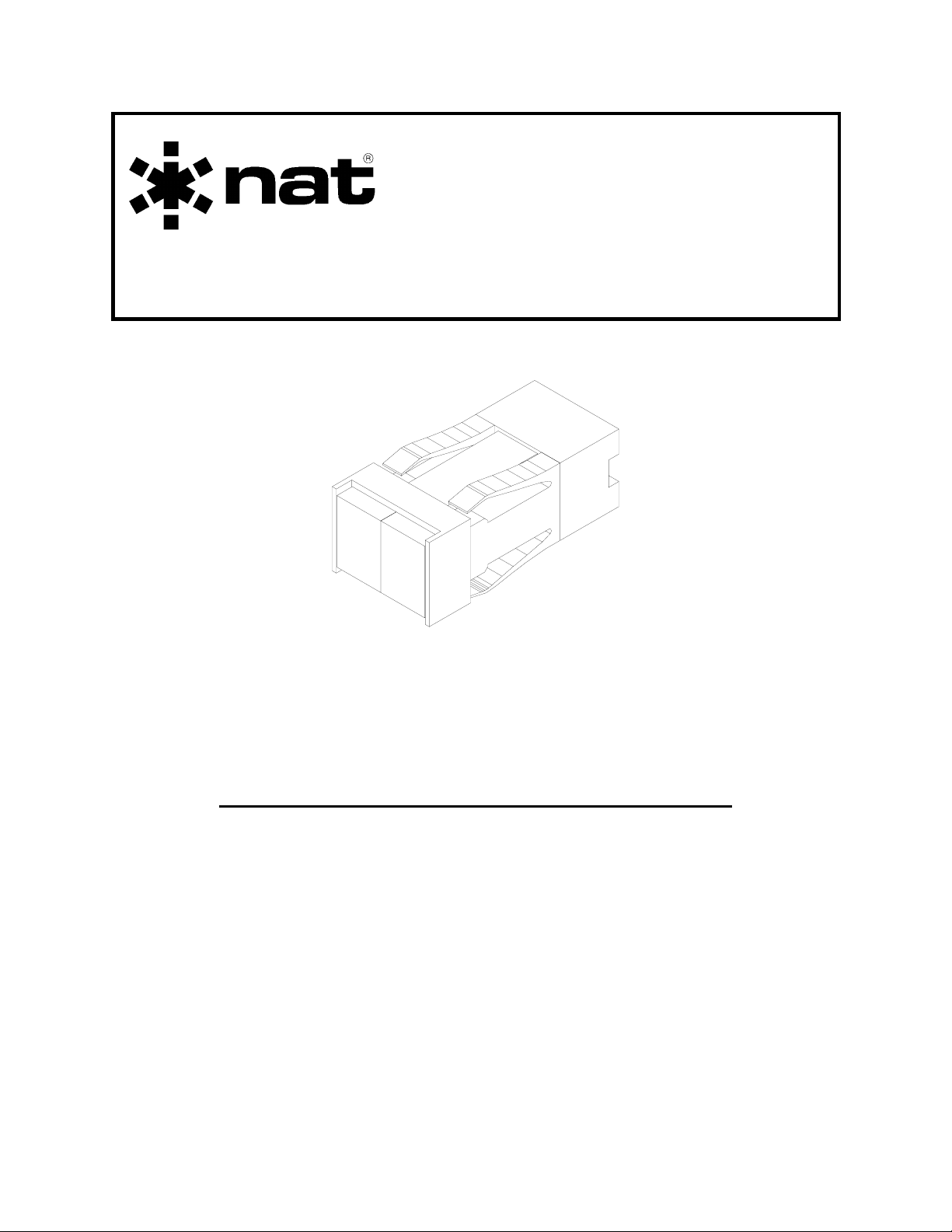
The PB08 is a positive action 2-pole switch with two individual legend lamps. The PB08
switch is designed for use with the RS08/RS12 series of remote switches from NAT.
1.3 Features
Units are shipped assembled (but with no legends inserted), and with lamps (28 V)
installed. The desired legends must be cut from the sheet provided and inserted inside
the lens cap. If 14 V operation is required, substitute type 386 lamps.
The combination of a two pole switch with two individual legend lamps is very effective
for GPS, LORAN or other NAV AID transfer switching and annunciation.
1.4 Specifications
1.4.1 Electrical Specifications
Lamp Power +14/+28 VDC at 200 mA max.
Lamps Type 388 for 28 V operation
Type 386 for 14 V operation
1.4.2 Physical Specifications
Height 17.9 mm (0.71 inches)
Length 48.5 mm (1.91 inches)
Width 23.8 mm (0.94 inches)
Mounting Front mounting, held in place by compression
fingers
Nov 24, 2003 Page 1-1
ENG-FORM: 800-0101.DOT
Page 8

PB08 Illuminated Pushbutton Switch Manual SM15 Rev. 4.00
Mounting hole height 14.9 mm (0.59 inches)
Mounting hole width 20.8 mm (0.82 inches)
1.5 Unit Nomenclature
The following list indicates the models available at the date of publication of this
document. Other models may be available.
Model Description / Distinction
PB08-001 2 section lighted pushbutton switch
Green/Blue segments with changeable legends and lamps (28
VDC lamps supplied)
Positive action (push on/push off)
2 pole output, individual lamps
Gold logic rated contacts
Ideal for GPS/LORAN/NAV selection
Interfaces with RS08/RS12
Supplied with assorted legends
PB08-002 Identical to the PB08-001 but with Green/Green segments
End of Section 1.0
Page 1-2 Nov 24, 2003
ENG-FORM: 800-0101.DOT
Page 9

SM15 Rev. 4.00 PB08 Illuminated Pushbutton Switch Manual
Section 2.0 Installation
2.1 General
Information in this section consists of: unpacking and inspection procedures, installation
procedures, post-installation checks and installation drawings.
2.2 Unpacking and Inspection
Unpack the equipment carefully and locate the warranty card. Inspect the unit visually
for damage due to shipping and report all such claims immediately to the carrier
involved. Note that each unit should have the following:
- PB08 Switch
- Legend Sheet
- Installation Manual
Verify that all items are present before proceeding and report any shortage immediately
to your supplier.
2.3 Installation Procedures
2.3.1 Warnings
These switches are very high quality, gold-contact units meant for logic switching. Do
not attempt to switch high-current loads (>200mA) with these contacts or permanent
damage will result.
2.3.2 Cautions
The lens assembly fits in the housing with either color to the right, so be sure to follow
the drawings in section 2.4 to ensure correct wiring.
2.3.3 Notes
Other lens combinations are available from NAT, or they can be interchanged with
legends from the LL08.
Nov 24, 2003 Page 2-1
ENG-FORM: 805-0101.DOT
Page 10

PB08 Illuminated Pushbutton Switch Manual SM15 Rev. 4.00
2.3.4 Installing the Legends
To install the required legends into the PB08, first examine the legends supplied and
pick out the combination that is most suitable for your application. Note that both
horizontal and vertical legends are provided. IN ALL CASES, the normal (or VOR/ILS)
legend should be the GREEN legend, to assure FAA compliance. Other legends can
be made with transfers, if needed.
Cut the legends along the border line and then into two individual sections using sharp
scissors. Withdraw the lens/diffuser assembly from the switch body by gripping the
lens cap on the provided notches and pulling out. A slight rocking motion will make it
easier. Pop the lenses off of the diffuser, and insert the legends of your choice, making
sure they are adequately trimmed and square. Replace the lenses, then push the
whole assembly back into the switch body. When it is firmly seated, it will lock into
place.
2.3.5 Changing Lamps
To replace or change lamps, withdraw the lens/diffuser assembly and pull out the lamp
with a pair of needle-nosed pliers. Push in a new lamp and press down on the top of
the lamp with the end of a pencil eraser or other object until the lamp clicks into place.
When it is correctly seated, it will not move farther in. Replace the lens assembly.
2.4 Installation Drawings
DRAWING REV. DESCRIPTION TYPE
PB08\403-0 1.01 PB08 Illuminated Pushbutton Switch Interconnect
PB08\904-0 1.01 PB08 Illuminated Pushbutton Switch Exploded View
PB08\701-0 1.00 PB08 Illuminated Pushbutton Switch Parts List
Section 2.0 ends after these Drawings
Page 2-2 Nov 24, 2003
ENG-FORM: 805-0101.DOT
Page 11

Confidential and Proprietary to NAT
Page 12

Page 13

Confidential and Proprietary to NAT
Page 14

Page 15

Confidential and Proprietary to NAT
PARTS LIST
NAT Part #: PB08-001 Description: Illuminated Pushbutton Switch
Document #: PB08\001\701-0 Rev: 1.00
Prepared By: Checked By: Approved By:
MFR. P/N
DESCRIPTION OR VALUE PACKAGE NAT P/N QTY.
IDENT
MECHANICAL PARTS
M101 Lamp/Switch Body 85-57-461 1
M102 Lamp, 28 VDC T1-3/4 45-01-388 2
M103 Blue/Green Lens Assembly * 85-82-461 1
M104 Legend Set 43-10-108 1
M105 Legend Set 43-10-208 1
* For other models replace with:
PB08-002
M103A Diffuser Assembly 85-82-001 1
M103B Lens, Green 85-82-005 2
OPTIONAL PARTS
M106 Lamp, 14V T1-3/4 45-01-386
M107 Lens, Amber 85-82-004
M108 Lens, Green 85-82-005
M109 Lens, Blue 85-82-006
End of Parts List
Rev 1.00 Oct 17, 1995 Page 1 of 1
ENG-FORM: 701-0100.DOT
Page 16

Page 17

SM15 Rev. 4.00 PB08 Illuminated Pushbutton Switch Manual
Section 3.0 Operation
3.1 Introduction
Information in this section consists of the functional and operating procedures for the
PB08 Illuminated Pushbutton Switch.
3.2 Performance
The PB08 switch provides a positive action two pole switch with two independent legend
lamps. It is very effective for GPS, LORAN or other NAV AID transfer switching and
annunciation.
The operation of the switch and the lamps are completely independent of each other;
the operation of the switch will have no direct effect on the lamps. Any relationship
between them must be accomplished through the aircraft wiring.
3.2.1 Switch Operation
The PB08 provides a switch with two sets of contacts, pins 1 and 2, and pins 3 and 4.
Both sets of contacts close when the switch is depressed and open when the switch is
depressed a second time.
3.2.2 Lamp Operation
The PB08 provides two lamps which operate completely independent of each other.
Two contacts are provided for each lamp and whether a lamp is lit or not depends
entirely on aircraft wiring.
End of Section 3.0
Nov 24, 2003 Page 3-1
ENG-FORM: 806-0101.DOT
Page 18

 Loading...