

Page 1
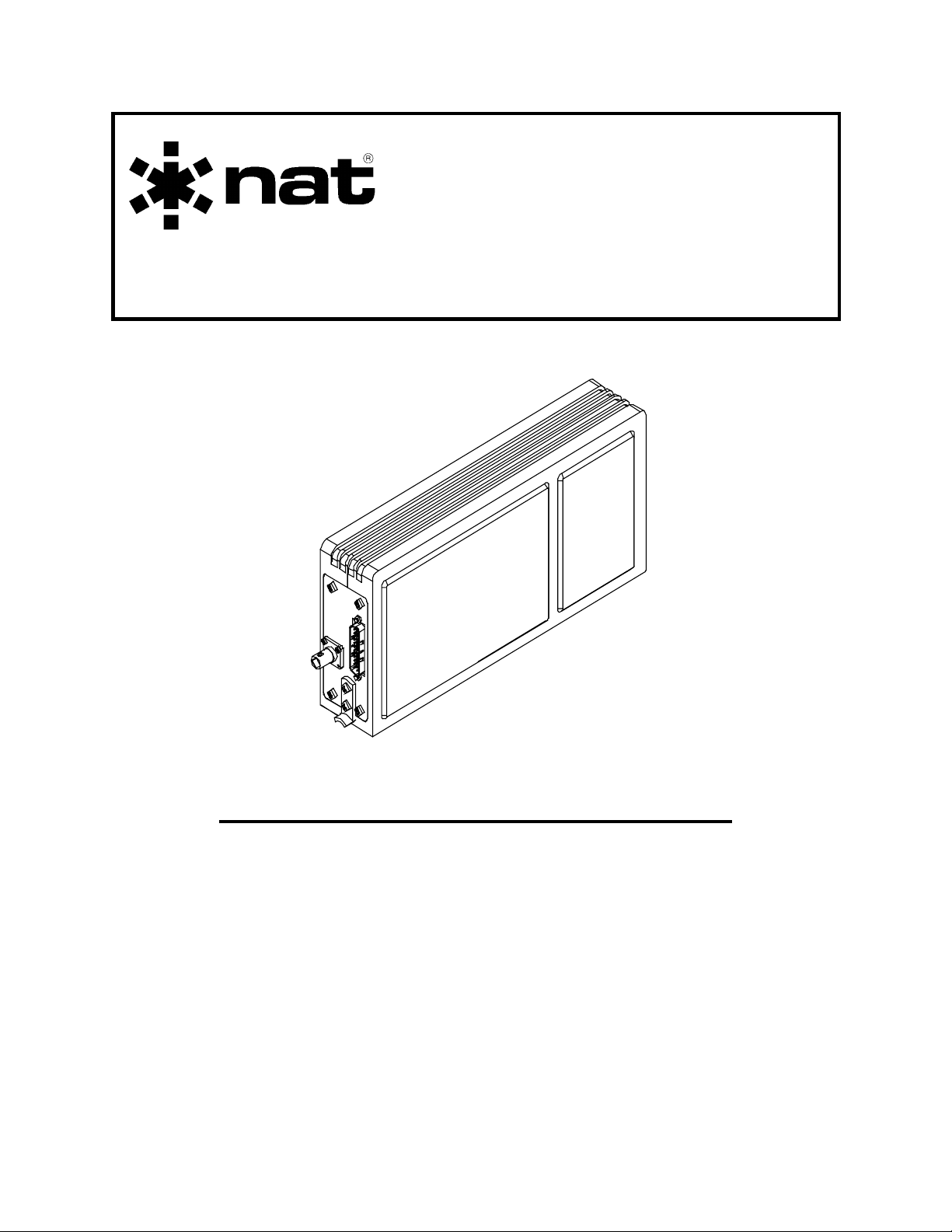
SM64
NTX403 Series
Remote Mount
UHF-FM Transceiver
INSTALLATION AND OPERATION MANUAL
REV 4.00 April 19, 2005
Northern Airborne Technology Ltd.
1925 Kirschner Road
Kelowna, BC, Canada.
V1Y 4N7
Telephone (250) 763-2232
Facsimile (250) 762-3374
Copyright 2005 by Northern Airborne Technology
CONFIDENTIAL AND PROPRIETARY TO NORTHERN AIRBORNE TECHNOLOGY LTD.
Page 2

Page 3

SM64 Rev. 4.00 NTX403 Series Remote Mount UHF-FM Transceiver Manual
Performed at factory
Periodically NAT will release manual amendments. In order to maintain the most
accurate and up to date manual these amendments should be carried out immediately
upon receipt and recorded on the following amendment record.
AMENDMENT RECORD
Amendment
Number
Note: Revision 4.00 is the first public release of this document
#1 Jan 7/08 2
Amendment
Date
Section(s)
Changed
Date
Entered
Entered By
Insert any Amendment Instruction sheets after this page.
Apr 19, 2005 Page ii
ENG-FORM: 820-0110.DOT
CONFIDENTIAL AND PROPRIETARY TO NORTHERN AIRBORNE TECHNOLOGY LTD.
Page 4

Page 5
INSTALL_OPS
MANUAL AMENDMENT
Manual: SM64 (NTX403 Series Remote Mount UHF-FM Transceiver) Amendment #: 1
Document # SM64\Install_Ops\809-0001 Amendment Date: Jan 7, 2008
The purpose of this amendment is to update sections 2.3.4, 2.3.5 and 2.3.6.
Amendment Instructions:
1
2-1, 2-2, 2-3, 2-4 and 2-5 Rev 4.00 2-1, 2-2, 2-3, 2-4 and 2-5 Rev 4.00
2 Update the Amendment Record sheet at the front of the manual.
3 Insert this page into the manual after the Amendment Record sheet (page ii).
Manual Amendment ends after the following amended pages
Remove Pages Replace With Pages
Amendment # 1
Amendment # 1 Jan 7, 2008
ENG-FORM: 809-0109.DOT
CONFIDENTIAL AND PROPRIETARY TO NORTHERN AIRBORNE TECHNOLOGY LTD.
Page 1
Page 6

Page 7

SM64 Rev. 4.00 NTX403 Series Remote Mount UHF-FM Transceiver Manual
Table of Contents
Section Title Page
1 Description
1.1 Introduction 1-1
1.2 Purpose of Equipment 1-1
1.3 Features 1-1
1.4 Specifications 1-1
1.4.1 Electrical Specifications 1-1
1.4.2 General Specifications 1-2
1.4.3 Physical Specifications 1-3
1.4.4 Environmental Specifications 1-4
2 Installation
2.1 Introduction 2-1
2.2 Unpacking and Inspection 2-1
2.2.1 Warranty 2-1
2.3 Installation Procedures 2-1
2.3.1 Warnings 2-1
2.3.2 Cautions 2-2
2.3.3 Notes 2-2
2.3.4 Cable and Wiring 2-2
2.3.5 Antennas 2-3
2.3.6 Mechanical Mounting 2-3
2.3.7 Post-Installation Checks 2-4
2.3.8 Post-Installation EMI Test 2-4
2.4 Continued Airworthiness 2-5
2.5 Accessories Required But Not Supplied 2-5
2.6 Installation Drawings 2-5
3 Operation
3.1 Introduction 3-1
3.2 General 3-1
3.3 Operation Specifics 3-1
Apr 19, 2005 Page iii
ENG-FORM: 820-0110.DOT
CONFIDENTIAL AND PROPRIETARY TO NORTHERN AIRBORNE TECHNOLOGY LTD.
Page 8

Page 9

SM64 Rev. 4.00 NTX403 Series Remote Mount UHF-FM Transceiver Manual
Section 1 Description
1.1 Introduction
This manual contains information on the NTX403 Remote Mount UHF-FM Transceiver.
All derivative products will be covered by manual supplements, which can be obtained
from NAT as required.
Information in this section consists of purpose of equipment, features and specifications.
1.2 Purpose of Equipment
The NTX403 is an UHF FM transceiver for operation in the 403 MHz to 512 MHz band.
The unit is remotely mounted using a 1/4 ATR tray and is operated via an RS-422 serial
bus interface using a TH-Series TAC/COM control head.
1.3 Features
The unit conforms to a 1/4 ATR tray size and is capable of receiving and transmitting
over 403.000 to 511.99375 MHz.
1.4 Specifications
1.4.1 Electrical Specifications
Power Supply +27.5 Vdc Power
Voltage: Nominal +27.5 Vdc
Maximum 30.3 Vdc
Minimum 22.0 Vdc
Emergency 18.0 Vdc
Current: Receive (Nom.) 500 mA @ +27.5 Vdc
Transmit (Max.) 2.5 A @ +27.5 Vdc
Input Signals
Mic Input Audio signal, 100 mVrms
Push to Talk Active ground signal, 15 mA max
Power On/Off Active ground signal, 20 mA max
Serial Data In RS-422 data from control head
Apr 19, 2005 Page 1-1
ENG-FORM: 800-0107.DOT
CONFIDENTIAL AND PROPRIETARY TO NORTHERN AIRBORNE TECHNOLOGY LTD.
Page 10

NTX403 Series Remote Mount UHF-FM Transceiver Manual SM64 Rev. 4.00
Output Signals
Headset Audio 100 mW Nominal, 250 mW max into 600 Ω
AUX Receive Audio 300 mVrms nominal, not tone controlled
RT Installed Low Output (Ground)
Main SQ Disable Out Active low output, open collector (20 mA max)
Serial Data Out RS-422 data to control head
Bi-directional Signals
RF Input / Output 50 Ω nominal antenna impedance
1.4.2 General Specifications
Frequency Range 403.000 to 511.99375 MHz
RF Impedance 50 Ω nominal
Modulation FM
Rated System Deviation 2.5 kHz (N
Rated Audio Input Level 100 mVrms nominal
Duty Cycle 20% (1 min. TX, 4 min. RX)
Sub-audible Tones 38 standard CTCSS tones and all DCS codes
Remote Interface RS-422 serial data
Number of channels 128, simplex or semi-duplex
Channel Increments 6.25 / 10 kHz
Scan Rate 10-20 channels/sec. All channels may be in
1.4.2.1 Transmitter
RF Output Power 10 W or 1 W ± 1dB
Frequency Stability ±2.5 ppm
Conducted Spurious ≤-13 dBm (50 µW)
Adjacent Channel Power ≥54 dBc (N
arrowband), 5 kHz (Wideband)
scan list.
arrowband), ≥70 dBc (Wideband)
Modulation Limiting 2.5 kHz (N
arrowband), 5 kHz (Wideband)
Microphone Impedance 150 Ω ±20%
AF Characteristic -6 dB/octave +1/-3 dB pre-emphasis (EIA STD)
Page 1-2 Apr 19, 2005
ENG-FORM: 800-0107.DOT
CONFIDENTIAL AND PROPRIETARY TO NORTHERN AIRBORNE TECHNOLOGY LTD.
Page 11

SM64 Rev. 4.00 NTX403 Series Remote Mount UHF-FM Transceiver Manual
Audio Distortion ≤5% THD
FM Hum/Noise Ratio ≤31 dB (Narrowband), ≤37 dB (Wideband)
Carrier Attack Time ≤100 ms maximum
Sidetone Level 35 ±15 mW nominal
1.4.2.2 Receiver
Reference Sensitivity ≤0.50 µV (-113 dBm)
Conducted Spurious ≤-87dBm
Adjacent Channel Rejection ≥60 dB (Narrowband), ≥70 dB (Wideband)
Spurious Rejection ≥70 dB, ≥65 dB at mixer spurious
Intermodulation Rejection ≥70 dB
Audio Output Power 100 ±10 mW into 600 Ω
Frequency Response +6 dB/octave +1/-3 dB de-emphasis (EIA STD)
Hum and Noise Ratio Unsquelched: ≥34 dB min. (Narrowband)
≥40 dB min. (W
Squelched: ≤-70 dBW
Audio Distortion ≤5% THD
Rx Attack Time ≤150 ms maximum
Rx Closing Time ≤250 ms maximum
1.4.3 Physical Specifications
ideband)
Height 5.22" (132.6 mm)
Depth 10.75" (273 mm) not incl. connectors
Width 2.23" (56.6 mm)
Weight 4.5 lbs. (2.0 kg) max
Mounting Custom NAT ¼ ATR tray (NTX-VT1)
Material/Finish 6061-T6 brushed aluminum with black powder
coat
Connectors One male 25-pin D-sub filtered with locking
tabs, and one BNC female
Apr 19, 2005 Page 1-3
ENG-FORM: 800-0107.DOT
CONFIDENTIAL AND PROPRIETARY TO NORTHERN AIRBORNE TECHNOLOGY LTD.
Page 12

NTX403 Series Remote Mount UHF-FM Transceiver Manual SM64 Rev. 4.00
1.4.4 Environmental Specifications
Temperature:
Operating -30º to +60º C
Short-time high +70º C
Ground survival -55º to +85º C
Altitude 25,000 ft
Humidity 95% for 48 hours
Operational Shock 6g for 11ms in all axes
Qualification: DO-160C Env. Cat. X-XX[MN]
DO-160D Env. Cat. B4-BABXXXXXXXZB
1
XXXXXXXXXXXXXXXX
2AB3
A[TT]4BXXXX
1
Vibration, DO-160C.
2
Power Input, DO-160D Change #2.
3
Ripple Voltage, DO-160D Change #2.
4
RF Susceptibility, DO-160D Change #1.
End of section 1
Page 1-4 Apr 19, 2005
ENG-FORM: 800-0107.DOT
CONFIDENTIAL AND PROPRIETARY TO NORTHERN AIRBORNE TECHNOLOGY LTD.
Page 13

SM64 Rev. 4.00 NTX403 Series Remote Mount UHF-FM Transceiver Manual
Section 2 Installation
2.1 Introduction
Information in this section consists of: unpacking and inspection procedures, installation
procedures, post-installation checks, and installation drawings.
2.2 Unpacking and Inspection
Unpack the equipment carefully and locate the warranty card. Inspect the unit visually
for damage due to shipping and report all such claims immediately to the carrier
involved. Note that each unit should have the following:
- NTX403 Series Remote Mount UHF-FM Transceiver
- Warranty Card
- Operator’s Manual
- Release certification
Verify that all items are present before proceeding and report any shortage immediately
to your supplier.
2.2.1 Warranty
Complete the warranty card information and send it to NAT when the installation is
complete. If you fail to complete the warranty card, the warranty will be activated on
date of shipment from NAT.
Note: An appropriately rated facility, e.g. Certified Aircraft Repair Station, must install
this equipment in accordance with applicable regulations. NAT Ltd’s warranty is
not valid unless the equipment is installed by an authorized NAT Dealer. Failure
to follow any of the installation instructions, or installation by a non-certified
individual or agency will void the warranty, and may result in a non-airworthy
installation.
2.3 Installation Procedures
2.3.1 Warnings
Do not bundle any lines from this unit with transmitter coax lines. Do not bundle any
logic, audio, or DC power lines from this unit with 400 Hz synchro wiring or AC power
lines. Do not position this unit next to any device with a strong alternating magnetic field
such as an inverter or significant interference to operation will result. In all installations,
use shielded cable exactly as shown
and ground as indicated. Significant problems
may result if these guidelines are not followed.
Apr 19, 2005 Page 2-1
ENG-FORM: 805-0106.DOT Amendment # 1 Jan 7, 2008
CONFIDENTIAL AND PROPRIETARY TO NORTHERN AIRBORNE TECHNOLOGY LTD.
Page 14

NTX403 Series Remote Mount UHF-FM Transceiver Manual SM64 Rev. 4.00
2.3.2 Cautions
Severe degradation of audio installations may result from incorrect wiring and shielding.
This could cause much higher cross-talk, hum, and ground-loop interference.
2.3.3 Notes
For maximum resistance to low frequency interference, the case of the transceiver must
be electrically grounded.
2.3.4 Cable and Wiring
All unshielded wire shall be selected in accordance with the original aircraft
manufacturer’s maintenance instructions or AC43.13-1B Change 1, Paragraphs 11-76
through 11-78. Wire types should be to MIL-W-22759 as specified in AC43.13-1B
Change 1, Paragraphs 11-85, 11-86, and listed in Table 11-11. For shielded wire
applications, use Tefzel MIL-C-27500 shielded wire with solder sleeves (for shield
terminations) to make the most compact and easily terminated interconnect. Follow the
wiring diagrams in Section 2.6 as required.
To provide easy installation of the hood, allow 3 inches from the end of the wire to the
shield termination. Note: Install the hood after the wiring is complete.
Installation cabling must allow the transceiver to be easily withdrawn for disconnection and
field service adjustments. Ensure an adequate service loop in the routing of the cables.
All wiring should be 22 AWG, except power and ground connections, which must be
18 AWG or larger, as indicated on the installation drawings. Ensure that the ground
connection is clean and well secured. To prevent inadvertent system failure, supply
power to this system from a separate breaker or fuse not connected to any other
device. NAT recommends a 5 A fuse or breaker (28 Vdc Source).
Coaxial cable should be in accordance with MIL-C-17 unless otherwise specified. Do
not use coax with PVC insulation. NAT recommends Teflon dielectric cable at or above
VHF frequencies or where cable runs exceed 8 feet. Note that at VHF frequencies,
cable losses due to long cable runs and tight bends may cut the ERP (Effective
Radiated Power) to less than 50% of specification.
To prevent RF interference between similar systems, NAT recommends that VHF FM
coax runs be widely separated, or be made using triaxial cable. Bond the outer shield to
the airframe at the transceiver end only.
In communication intensive applications, bad cable routing and shielding may drastically
compromise over-all system performance. Symptoms will be spurious squelch opening,
RFI (Radio-Frequency Interference), and garbled reception.
Neatly terminate RF cables (solder or crimp) and test for shorts prior to system checkout (not while connected to the radio!!). Keep cable bends to a minimum at the antenna.
Page 2-2 Apr 19, 2005
ENG-FORM: 805-0106.DOT Amendment # 1 Jan 7, 2008
CONFIDENTIAL AND PROPRIETARY TO NORTHERN AIRBORNE TECHNOLOGY LTD.
Page 15

SM64 Rev. 4.00 NTX403 Series Remote Mount UHF-FM Transceiver Manual
Avoid sharp bends in the coax cables (minimum 3" radius) to prevent severe reflections.
If sharp bends are required use 90° elbow adapters.
Fabrication and installation of wiring harness should be in accordance with the original
aircraft manufacturer’s maintenance instructions or AC43.13-1B Change 1, chapter 11,
sections 5 to 13, 16 and 17.
Grounding and bonding should be in accordance with the original aircraft manufacturer’s
maintenance instructions or AC43.13-1B Change 1, chapter 11, section 15.
2.3.5 Antennas
Correct antenna placement and mounting is critical in order to achieve the best possible
performance. In general, keep all antennas as widely separated as possible and clear of
any large airframe obstructions. Avoid any placement that puts antennas of like
frequencies close together.
Installation of the antenna should be in accordance with the original aircraft
manufacturer’s instructions for continued airworthiness or AC43.13-1B Change 1,
chapter 11, section 15 and AC 43.13-2A chapter 3. If possible, the antenna should be
located a minimum of 12 ft from aircraft navigation receiver antennas and a minimum of
4 ft from aircraft communications and ELT antennas. Be careful not to choose
separations that closely approximate ¼, ½ or whole number multiples of the navigation
or communication system wavelengths.
Bottom mounted antennas will perform best in flight, but poorest on the ground during
testing. Antennas may be severely degraded by 'masking' effects of the fuselage or
stabilizers, and generally give best performance when bottom mounted.
Surround any blade or whip antenna with a ground plane surface (metallic, grounded
material) having a radius equal to or greater than the height of the antenna. Poor
grounding will result in severe reflected power and high levels of RFI throughout the
airframe.
Any antenna will be less prone to interference from rotor modulation and other undesirable
stimuli if installed correctly and surrounded by a large metallic ground plane. Under the
same conditions, it is also much less likely to cause interference to other aircraft systems
(e.g., coupling into audio system, fluctuations in instrumentation, etc.). Poor grounding will
result in severe reflected power and high levels of RFI throughout the airframe.
Avoid antenna locations that will become fouled with oil, water, fuel or dirt, as this will
degrade performance. Roof mounts (in close proximity to rotor blades) are permissible.
2.3.6 Mechanical Mounting
Installation of the transceiver should be in accordance with the original aircraft
manufacturer’s instructions for continued airworthiness or AC 43.13-1B Change 1,
chapter 7, sections 2 to 7, and AC 43.13-2A chapter 2.
Apr 19, 2005 Page 2-3
ENG-FORM: 805-0106.DOT Amendment # 1 Jan 7, 2008
CONFIDENTIAL AND PROPRIETARY TO NORTHERN AIRBORNE TECHNOLOGY LTD.
Page 16

NTX403 Series Remote Mount UHF-FM Transceiver Manual SM64 Rev. 4.00
The transceiver is tray-mounted and uses a custom 1/4 ATR style tray. Mount (with
countersunk screws) onto a clean, grounded surface having a resistance of less than
0.5 ohms to airframe ground.
The transceiver may be mounted in any attitude, but upright (mounting hook at the
bottom) is preferred for access and condensation drainage.
2.3.7 Post-Installation Checks
2.3.7.1 Voltage/resistance checks
Do not attach the transceiver until the following conditions are met.
Check the following:
a) P1 pins <5> and <6> for +28 Vdc relative to ground.
b) P1 pins <8> and <20> for continuity to ground (below 0.5 Ω).
Ensure that the antenna is disconnected for the following test or erroneous
readings may be obtained.
c) Radio coax connector for continuity to the antenna coax connector (shield and
centre conductor) and for open circuit from the centre conductor to ground and
open circuit from the centre conductor to the shield.
2.3.7.2 Power On checks
a) Install the transceiver and power up the ship’s systems. Turn on the control head.
Check the operation of all front panel controls. Adjust brightness and volume
levels as required.
b) Check all transmit and receive functions. Ensure the RX/TX status indicator lights
green when keying the radio to transmit and amber when receiving.
c) Check the SCAN function.
Note: You may be unable to hear the received audio if the tones do not match
those set in the radio. To avoid any confusion, set the tones to OFF (via
the Status Edit mode) during scanning so that all channels will be heard.
d) Check the antenna feedline at the R/T with a through-line wattmeter and suitable
frequency elements to ensure correct antenna matching. Reflected power in
excess of 25% represents a serious problem, and should be investigated
carefully, or serious RFI and system interference as well as possible radio
damage may result. A VSWR measurement of over 3.0:1 represents a significant
loss in signal power to the antenna. Check that forward power is to specifications
over the frequency band of the radio.
Page 2-4 Apr 19, 2005
ENG-FORM: 805-0106.DOT Amendment # 1 Jan 7, 2008
CONFIDENTIAL AND PROPRIETARY TO NORTHERN AIRBORNE TECHNOLOGY LTD.
Page 17

SM64 Rev. 4.00 NTX403 Series Remote Mount UHF-FM Transceiver Manual
2.3.8 Post-Installation EMI Test
The purpose of this test is to identify any interference that the transceiver may cause
with existing aircraft systems. The transceiver should be tested in accordance with the
Installation Approval Test Procedure (see section 2.6) and the test results documented
on the record sheets.
Upon satisfactory completion of all performance checks, make the required log
entries and complete the necessary Regulatory Agency paperwork before
releasing the aircraft for service.
2.4 Continued Airworthiness
Maintenance of the NTX403 is ‘on condition’ only. Periodic maintenance of this product
is not required.
2.5 Accessories Required But Not Supplied
Installation kit p/n NTX-IKC (crimp) is required to complete the installation. The kit
consists of the following:
Quantity Description NAT Part #
1 Field Serviceable BNC Coax Connector 20-51-001
1 1/4 ATR NTX Mounting Tray NTX-VT1
1 D-min 25 Pin Female Crimp Installation Kit D25SV-IKC
Consisting of:
Quantity Description NAT Part #
1 D-min 25 Socket housing 20-21-025
25 MS Crimp Socket 20-26-901
1 25 pin JVL Hood/Locklever 20-29-250
2.6 Installation Drawings
DRAWING REV. DESCRIPTION TYPE
NTX403\403-0 1.00 NTX UHF Radio Connections Interconnect
NTX403\405-0 1.00 UHF FM Transceiver Connector Map
NTX403\634-0 1.00 UHF FM Transceiver Installation Approval Test Procedure
NTX403-000\922-0 1.00 Remote Mount UHF FM Transceiver Mechanical Installation
Section 2 ends after these Drawings
Apr 19, 2005 Page 2-5
ENG-FORM: 805-0106.DOT Amendment # 1 Jan 7, 2008
CONFIDENTIAL AND PROPRIETARY TO NORTHERN AIRBORNE TECHNOLOGY LTD.
Page 18

Page 19

Page 20

Page 21

Page 22

Page 23

INSTALLATION APPROVAL TEST
NAT Part #: NTX403 Description: Remote Mount UHF FM Transceiver
Document #: NTX403\634-0 Rev: 1.00
1. Post Installation EMI Test
The purpose of this test is to identify any interference that the NTX403 may cause with
existing aircraft systems.
2. Test Conditions
The NTX403 should be installed and function tested. The antenna VSWR should be
checked. A forward/reverse power check with an in-line wattmeter should show no
more than 10% reflected power. For the following tests, ensure that the transmit power
is set to HI.
3. Methodology
PROCEDURE
Most of the EMI tests can be accomplished on the ground. In some cases flight testing
is required or is easier. If the aircraft is approved for IFR operations, then it is mandatory
that interference between the NTX403 Airborne FM and the approach aids be checked
in flight.
The GPS should be operational and navigating with at least the minimum compliment of
satellites. The VHF comm should be set to the frequencies indicated with the squelch
open. VOR/DME receivers should be set to the frequencies indicated and selected for
display. If possible, set up a DME ramp test set on the frequencies indicated and adjust
the output until the flags are out of view. The transponder and encoder should be
monitored with ramp test equipment. Set the output of the transponder test set to 3 dB
above the output necessary to achieve 90% reply. If possible set the ADF to a nearby
navigation station.
Modulate the NTX403 transmitter on the indicated frequencies for at least 20 seconds.
Observe the GPS for any degradation in satellite status or availability or flags. Listen for
any noise or detected audio signals on the VHF comm(s). Listen for any noise or
detected audio signals on the VOR/LOC receiver audio; look for any movement of flags
or needles on the VOR/LOC/GS navigation display(s). Observe the transponder for any
loss of reply or spurious reply.
List the power plant, fuel and other electric instruments in the chart provided and note
any anomalies that occur while transmitting. Assess the results.
If the aircraft is equipped with an autopilot or a stability augmentation system, then test
fly the aircraft and verify that operation of the NTX403 transceiver does not have
adverse effects on these systems. After checking for gross effects at a safe altitude, fly
Rev. 1.00 Apr 28, 2005 Page 1 of 5
ENG-FORM: 634-0101.DOT
CONFIDENTIAL AND PROPRIETARY TO NORTHERN AIRBORNE TECHNOLOGY LTD.
Page 24

NTX403 Installation Approval Test Procedure
an approach with each of the different navigation systems coupled to the autopilot (ILS,
GPS etc.) and look for any anomalies.
4. Results
If the installed system passes all of the applicable EMI tests, then no further action is
required. If interference is observed, then the interference must be assessed against
the appropriate standards of airworthiness for the system in question. For example: it is
permissible for a VFR certified GPS to lose navigation capability while the NTX403 is
transmitting, providing that it recovers properly and promptly, but it is not permissible for
an IFR Approach certified GPS to be affected in the same way. A complete discussion
of all the standards of airworthiness to be applied in assessing EMI effects is beyond
the scope of this document.
5. Procedure
A. Operate the NTX403 transmitter on the following frequencies for at least 20 seconds.
Observe the GPS for any degradation in satellite status, or availability, or flags.
FREQUENCIES GPS #1 GPS #2
NOTES:
NTX403 PASS FAIL PASS FAIL
409.2000 MHz
Rev. 1.00 Apr 28, 2005 Page 2 of 5
ENG-FORM: 634-0101.DOT
CONFIDENTIAL AND PROPRIETARY TO NORTHERN AIRBORNE TECHNOLOGY LTD.
Page 25

NTX403 Installation Approval Test Procedure
B. Modulate the NTX403 transmitter on the following frequencies for at least 20
seconds. Look for loss of distance information on the display.
FREQUENCIES RESULTS
DME 1 NTX403 PASS FAIL
978 (108.0) 489.0000
1020 (112.1) 510.0000
FREQUENCIES RESULTS
DME 2 NTX403 PASS FAIL
978 (108.0) 489.0000
1020 (112.1) 510.0000
NOTES:
Note: For the following tests, select frequencies at the top, middle and bottom of the
range of the NTX403.
Frequency #1 ______________ Frequency #2 ______________
Frequency #3 ______________
E. At a safe altitude, engage the autopilot or stability augmentation system.
Modulate the NTX403 transmitter on the above frequencies for at least 20
seconds. Observe any effect on the autopilot or stability augmentation system.
Observations:
Rev. 1.00 Apr 28, 2005 Page 3 of 5
ENG-FORM: 634-0101.DOT
CONFIDENTIAL AND PROPRIETARY TO NORTHERN AIRBORNE TECHNOLOGY LTD.
Page 26

NTX403 Installation Approval Test Procedure
F. Perform a coupled ILS approach to the aircraft's certified limits. Modulate the
NTX403 transmitter on the above frequencies for at least 20 seconds. Observe
any effect on the autopilot. Repeat for each different system such as ILS #2,
GPS, FMS etc.
Observations:
G. List the power plant, fuel and other electric instruments in the chart provided and
note any anomalies that occur while transmitting. Assess the results.
STEP SYSTEM PASS FAIL NOTES
1 Com 1&2
2 VOR/LOC 1&2
3 Glideslope 1&2
4 Xponder & Encoder
5 ADF 1 & 2
6 VG
7 Compass
8 Directional Gyro
9 Oil Pressure
10 Fuel Pressure
11 Oil Temp
12 Amps
13 Bus Voltage
14 Fuel %
15 Ng
16 TOT
17 Torque %
Rev. 1.00 Apr 28, 2005 Page 4 of 5
ENG-FORM: 634-0101.DOT
CONFIDENTIAL AND PROPRIETARY TO NORTHERN AIRBORNE TECHNOLOGY LTD.
Page 27

NTX403 Installation Approval Test Procedure
STEP SYSTEM PASS FAIL NOTES
18 Annunciators
19 Digital Clock
NOTES:
End of installation approval test procedure
Rev. 1.00 Apr 28, 2005 Page 5 of 5
ENG-FORM: 634-0101.DOT
CONFIDENTIAL AND PROPRIETARY TO NORTHERN AIRBORNE TECHNOLOGY LTD.
Page 28

Page 29

Page 30

Page 31

SM64 Rev. 4.00 NTX403 Series Remote Mount UHF-FM Transceiver Manual
Section 3 Operation
3.1 Introduction
Information in this section consists of the functional and operational procedures for the
NTX403 Series Remote Mount UHF-FM Transceiver.
3.2 General
The NTX403 is an UHF FM transceiver for operation in the 403 MHz to 512 MHz band.
The unit is remotely mounted using a 1/4 ATR tray and is operated via an RS-422 serial
bus interface using a TH-Series TAC/COM control head.
3.3 Operation Specifics
The NTX403 Series Remote Mount UHF-FM Transceiver has no user operational
aspects. During installation, or if the unit has been exchanged, it may be a requirement
to change internal adjustments. This should be done ONLY BY FULLY QUALIFIED
PERSONNEL.
End of section 3
Apr 19, 2005 Page 3-1
ENG-FORM: 806-0106.DOT
CONFIDENTIAL AND PROPRIETARY TO NORTHERN AIRBORNE TECHNOLOGY LTD.
Page 32

 Loading...