

Page 1
SM71
NTA01-001
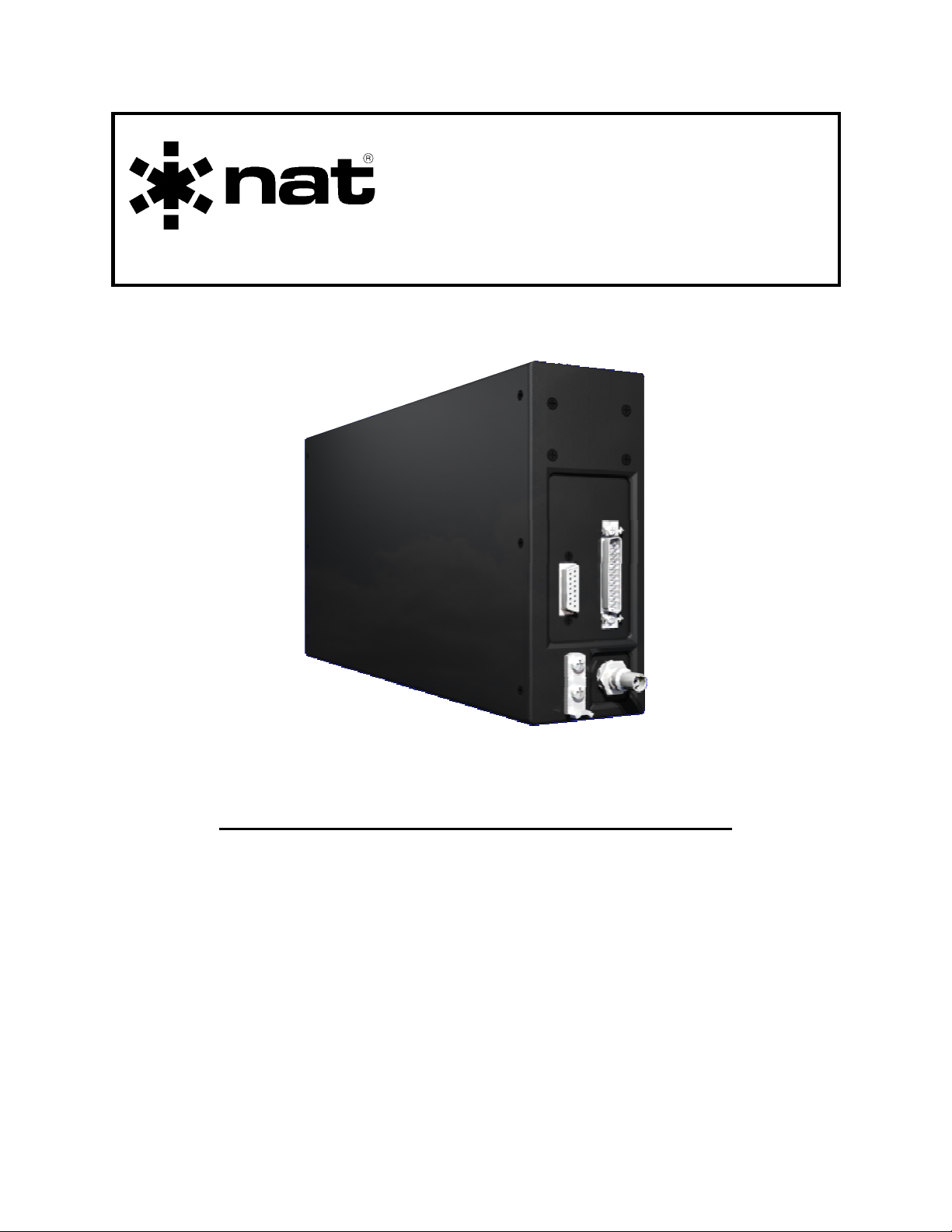
Motorola Series Radio Adapter
INSTALLATION AND OPERATION MANUAL
REV 4.10 February 6, 2006
Northern Airborne Technology Ltd.
1925 Kirschner Road
Kelowna, BC, Canada.
V1Y 4N7
Telephone (250) 763-2232
Facsimile (250) 762-3374
Copyright 2006 by Northern Airborne Technology
CONFIDENTIAL AND PROPRIETARY TO NORTHERN AIRBORNE TECHNOLOGY LTD.
Page 2

Page 3
SM71 Rev. 4.10 NTA01-001 Motorola Series Radio Adapter Manual
Periodically NAT will release manual amendments. In order to maintain the most
accurate and up to date manual these amendments should be carried out immediately
upon receipt and recorded on the following amendment record.
AMENDMENT RECORD
Amendment
Number
Amendment
Date
Note: Revision 4.00 was the first public release of this document
Section(s)
Changed
Date
Entered
Entered By
Insert any Amendment Instruction sheets after this page.
Feb 6, 2006 Page ii
ENG-FORM: 820-0109.DOT
CONFIDENTIAL AND PROPRIETARY TO NORTHERN AIRBORNE TECHNOLOGY LTD.
Page 4

Page 5

SM71 Rev. 4.10 NTA01-001 Motorola Series Radio Adapter Manual
Table of Contents
Section Title Page
1 Description
1.1 Introduction 1-1
1.2 Purpose of Equipment 1-1
1.3 Features 1-1
1.4 Specifications 1-2
1.4.1 Electrical Specifications 1-2
1.4.2 Physical Specifications 1-4
1.4.3 Environmental Specifications 1-4
2 Installation
2.1 Introduction 2-1
2.2 Unpacking and Inspection 2-1
2.2.1 Warranty 2-1
2.3 Installation Procedures 2-1
2.3.1 Warnings 2-1
2.3.2 Cautions 2-2
2.3.3 Cabling and Wiring 2-2
2.3.4 Installation of Radio into NTA01-001 2-2
2.3.5 Post-Installation Checks 2-3
2.3.6 Adjustments 2-3
2.4 Continued Airworthiness 2-4
2.5 Accessories Required But Not Supplied 2-4
2.6 Installation Drawings 2-4
3 Operation
3.1 Introduction 3-1
3.2 General 3-1
3.3 Operation Specifics 3-1
Feb 6, 2006 Page iii
ENG-FORM: 820-0109.DOT
CONFIDENTIAL AND PROPRIETARY TO NORTHERN AIRBORNE TECHNOLOGY LTD.
Page 6

Page 7

SM71 Rev. 4.10 NTA01-001 Motorola Series Radio Adapter Manual
Section 1 Description
1.1 Introduction
This manual contains information on the NTA01-001 Motorola Series Radio Adapter.
All derivative products will be covered by manual supplements which can be obtained
from NAT as required.
Information in this section consists of purpose of equipment, features and specifications.
Note: The NTA01-001 Motorola Series Radio Adapter has been designed for use with
the remote-mounted version of Motorola’s Astro and XTL-series radios. If there
is any question about the suitability of the NTA01-001 for a specific Motorola
radio, contact the Product Support department at NAT Ltd.
1.2 Purpose of Equipment
The NTA01-001 is a remote-mounted adapter unit, specifically designed to incorporate
the remote-mounted version of Motorola’s Astro and XTL-series radios into an aircraft
environment. It provides all required interface functions to integrate a car/motorcycle
radio into an aircraft environment, such as power conversion, mic excitation, sidetone
generation, impedance matching and level conversion.
1.3 Features
The NTA01-001 is a tray-mounted unit that accepts remote-mounted versions of the
Motorola radio (7 inches long maximum and with a 15-watt transmit maximum radio).
The preferred method of control of the Motorola radio is via a TH-Series Tac/Com
Control head with a suitable radio interface installed in it.
The NTA01-001 provides voltage conversion from +28 to +13 Vdc, mic bias for
amplified microphones, a remote on/off line (supplied by the control head), artificial
sidetone during transmission, and level and impedance matching of the radio’s audio
signals to the aircraft audio system.
Programming of the Motorola Astro radio is accomplished with a PC and a Motorola RIB or
SRIB box and Motorola RSS programming software via a 15-pin connector on the front of
the NTA01-001. This feature is not available with the XTL-series radios.
Feb 6, 2006 Page 1-1
ENG-FORM: 800-0108.DOT
CONFIDENTIAL AND PROPRIETARY TO NORTHERN AIRBORNE TECHNOLOGY LTD.
Page 8

NTA01-001 Motorola Series Radio Adapter Manual SM71 Rev. 4.10
1.4 Specifications
1.4.1 Electrical Specifications
Power Supply One switcher and one linear regulator with over-
voltage, over-current and thermal protection.
Operating Voltages:
Nominal +27.5 Vdc
Maximum +30.3 Vdc
Minimum +22.0 Vdc
Emergency +18.0 Vdc
Current Consumption
NTA01-001 only 250 mA @ +28 Vdc
With radio 500 mA typical @ +28 Vdc Standby
2.75 A typical @ +28 Vdc transmitting at 10 W
Power Output to radio +13 Vdc ±10% @ 5 A max. (20% duty cycle)
Internal Fuse 7 A
Breaker Current Rating 5 A
Input Signals
Mic Input from audio control panel:
Level 250 mVrms
Mic AC Input Impedance 150 Ω ±10%
Mic DC Input Impedance 470 Ω ±10%
Input Type Single ended
Speaker Input from radio:
Level 6.4 Vrms
Input Impedance 600 Ω ±10%
Input Type Balanced
Power On/Off:
Level <1 Vdc (logic low)
>3 Vdc (logic hi)
Page 1-2 Feb 6, 2006
ENG-FORM: 800-0108.DOT
CONFIDENTIAL AND PROPRIETARY TO NORTHERN AIRBORNE TECHNOLOGY LTD.
Page 9

SM71 Rev. 4.10 NTA01-001 Motorola Series Radio Adapter Manual
Output Signals
Mic Output to radio:
Level 150 mVrms ±10% into 150 Ω
Output Type Balanced
Receive Audio Output to audio control panel:
Receive Audio Level 100 mW into 600 Ω nominal
Sidetone Audio Level 25 mW into 600 Ω nominal
Output Type Balanced
Frequency Response <3 dB from 350 Hz to 6000 Hz
Distortion <10% @ rated output
Noise Level Without Signal >50 dB down from rated output
Receive Audio Output Regulation <10% variation when the load is changed to
75% and 400% of the rated load
Relay Contacts 1 A @ 30 Vdc max. (Closed when keyline active)
Bi-directional Signals
RF Input/Output Impedance 50 Ω
Floating lines that pass through the NTA01-001 to the Radio:
Lines from J1 to J104: Lines from J2 to J102:
RESET CTS-RS232
A+ EMER
DIG GND N/C SPARE
SW B+ SW B+
BUSY N/C SPARE
BUS + SPKR HI
BUS – SPKR LO
BUS SHIELD DIG GND
ANA GND BUSY
RADIO ON/OFF BUS –
N.O. CONTACT RX-RS232
WIPER N/C SPARE
TX-RS232
BUS +
RTS-RS232
Feb 6, 2006 Page 1-3
ENG-FORM: 800-0108.DOT
CONFIDENTIAL AND PROPRIETARY TO NORTHERN AIRBORNE TECHNOLOGY LTD.
Page 10

NTA01-001 Motorola Series Radio Adapter Manual SM71 Rev. 4.10
1.4.2 Physical Specifications
Height 7.29" (185.2 mm) max.
Depth 14.02" (356.1 mm) max. (not including connector)
Width 2.99" (75.9 mm) max.
Weight 4.51 lbs. (2.0 kg) max. (without Radio installed)
Mounting Vertical Tray Mount (custom size)
Part Number: NTA-VT1
Finish Black anodized
Connectors Male 25 pin D-sub connector with V5 Locktabs
Female 15 pin D-sub connector (no locking
hardware)
Female TNC
Installation Kit NAT part #: NTA-IKC
1.4.3 Environmental Specifications
Operating Temperature:
Low -30° C
High +60° C
Short-time High +60° C
Ground Survival Temperature:
Low -40° C
High +85° C
Altitude +15,000 ft (+4,572 m).
Shock Operational 6 g for 11 ms in all axes.
Crash Safety, Impulse 20 g for 11 ms in all axes.
Crash Safety, Sustained 20 g for 3 s in all axes.
Qualification
DO-160D Env. Cat. A4-BXB[(SM)(UF)]
1 Vibration testing is being performed to pre-Change 1.
2 Only the Normal Operating Conditions (DC) will be tested.
1
XXXXXXXB2AXXXBXXXX
Vibration DO-160D, Sec. 8.0, Cat. (SM)(UF)
End of section 1
Page 1-4 Feb 6, 2006
ENG-FORM: 800-0108.DOT
CONFIDENTIAL AND PROPRIETARY TO NORTHERN AIRBORNE TECHNOLOGY LTD.
Page 11

SM71 Rev. 4.10 NTA01-001 Motorola Series Radio Adapter Manual
Section 2 Installation
2.1 Introduction
Information in this section consists of: unpacking and inspection procedures, installation
procedures, post-installation checks, and installation drawings.
2.2 Unpacking and Inspection
Unpack the equipment carefully and locate the warranty card. Inspect the unit visually
for damage due to shipping and report all such claims immediately to the carrier
involved. Note that each unit should have the following:
- NTA01-001 Motorola Series Radio Adapter
- Warranty Card
- Operator’s Manual
- Release certification
Verify that all items are present before proceeding and report any shortage immediately
to your supplier.
2.2.1 Warranty
Complete the warranty card information and send it to NAT when the installation is
complete. If you fail to complete the warranty card, the warranty will be activated on
date of shipment from NAT.
Note: An appropriately rated facility, e.g. Certified Aircraft Repair Station, must install
this equipment in accordance with applicable regulations. NAT Ltd’s warranty is
not valid unless the equipment is installed by an authorized NAT Dealer. Failure
to follow any of the installation instructions, or installation by a non-certified
individual or agency will void the warranty, and may result in a non-airworthy
installation.
2.3 Installation Procedures
2.3.1 Warnings
Do not bundle any lines from this unit with transmitter coax lines. Do not bundle any
logic, audio, or DC power lines from this unit with 400 Hz synchro wiring or AC power
lines. Do not position this unit next to any device with a strong alternating magnetic field
such as an inverter or significant interference to operation will result. In all installations,
use shielded cable exactly as shown
and ground as indicated. Significant problems
may result if these guidelines are not followed.
Feb 6, 2006 Page 2-1
ENG-FORM: 805-0106.DOT
CONFIDENTIAL AND PROPRIETARY TO NORTHERN AIRBORNE TECHNOLOGY LTD.
Page 12

NTA01-001 Motorola Series Radio Adapter Manual SM71 Rev. 4.10
2.3.2 Cautions
All audio installations can be severely degraded by incorrect wiring and shielding, and
may result in much higher cross-talk, hum, and ground-loop interference. This should
be considered when audio wiring to and from the radio system installation is
performed.
In communication intensive applications, poor cable routing and shielding may drastically
compromise over-all system performance. Use caution in the routing of wire bundles.
2.3.3 Cabling and Wiring
All unshielded wire shall be selected in accordance with AC43.13-1B Change 1,
Paragraphs 11-76 through 11-78. Wire types should be to MIL-W-22759 as specified in
AC43.13-1B Change 1, Paragraphs 11-85, 11-86, and listed in Table 11-11. For
shielded wire applications, use Tefzel MIL-C-27500 shielded wire with solder sleeves
(for shield terminations) to make the most compact and easily terminated interconnect.
Follow the wiring diagrams in Section 2.6 as required.
Allow 3 inches from the end of the wire to the shield termination to allow the hood to be
easily installed. Note that the hood is a ‘clamshell’ hood, and is installed after the wiring
is complete.
All wiring should be at least 22 AWG, except where otherwise specified. Ensure that all
ground connections are clean and well secured.
2.3.4 Installation of Radio into NTA01-001
Refer to Mechanical Installation drawing NTA01\001\952-0.
Remove the cover from the NTA01-001. The necessary cables and screws for
connecting and fitting the radio are inside the unit in anti-static bags.
Attached to the inside of the unit closest to the external connectors is the RF coaxial
cable connector, the power supply connector, and a 15-pin ribbon cable (J102), and at
the other end of the unit is a 25-pin ribbon cable. These should be attached to the
appropriate connectors on the radio.
Note: If an XTL-series radio is to be installed, the 15-pin ribbon cable (J102) is not
used, and must be removed to allow proper installation of the radio.
Inside one of the bags there are four panhead screws that should be used to attach the radio
inside the NTA01-001 through the cover, and also sufficient flathead screws to fasten the
cover into place.
Note: In some cases it may be necessary to use a 90º adaptor for the coaxial cable.
Page 2-2 Feb 6, 2006
ENG-FORM: 805-0106.DOT
CONFIDENTIAL AND PROPRIETARY TO NORTHERN AIRBORNE TECHNOLOGY LTD.
Page 13

SM71 Rev. 4.10 NTA01-001 Motorola Series Radio Adapter Manual
2.3.5 Post-Installation Checks
2.3.5.1 Voltage/Resistance Checks
Do not attach the NTA01-001 until the following conditions are met.
Check the following:
a) P1 pins <1> and <2> for +28 Vdc relative to ground.
b) P1 pins <3>, <4> and <21> for continuity to ground.
2.3.5.2 Power On Checks
a) Install the NTA01-001 and power up the ship’s systems. Turn on the radios and
accessories required for the system.
b) Check for correct radio audio and adjust for acceptable level.
2.3.5.3 Performance Checks
If any preset requires adjustment, be sure this is carried out before the aircraft leaves,
and that the unit and its mating connector are secured before departure. Make all
required log book entries, electrical load, weight and balance amendments and other
paperwork as required by your local regulatory agency.
Upon satisfactory completion of all performance checks, make the required log
entries and complete the necessary Regulatory Agency paperwork before
releasing the aircraft for service.
2.3.6 Adjustments
The unit is shipped from the factory with all internal adjustments set to the normal test
levels. Once installed in the aircraft, it may be desirable to change some of these
settings to best suit the local operating environment.
MIC LEVEL SIDETONE RX LEVEL
The internal adjustments that can be varied can be found on the top of the rear
subassembly after removing the cover of the unit, and are mic level, sidetone, and RX
level, as shown above.
These levels can be adjusted using the rotary pots. Rotating the pots clockwise
increases the levels, and counterclockwise decreases the levels.
Feb 6, 2006 Page 2-3
ENG-FORM: 805-0106.DOT
CONFIDENTIAL AND PROPRIETARY TO NORTHERN AIRBORNE TECHNOLOGY LTD.
Page 14

NTA01-001 Motorola Series Radio Adapter Manual SM71 Rev. 4.10
2.4 Continued Airworthiness
Maintenance of the NTA01-001 is ‘on condition’ only. Periodic maintenance of this
product is not required.
2.5 Accessories Required But Not Supplied
Installation kit p/n NTA-IKC (crimp) is required to complete the installation. The kit
consists of the following:
Quantity Description NAT Part #
1 TNC Coax Connector 20-55-225
1 NTA Mounting Tray NTA-VT1
1 D-min 25 Pin Female Crimp Installation Kit D25SV-IKC
NAT Part # D25SV-IKC consists of:
Quantity Description NAT Part #
1 D-min 25 Socket housing 20-21-025
25 MS Crimp Socket 20-26-901
1 25 pin JVL Hood/Locklever 20-29-250
Notes:
1. All parts are packaged unassembled.
2. Coaxial cable not supplied.
2.6 Installation Drawings
DRAWING REV. DESCRIPTION TYPE
NTA01\001\403-0 1.10 Astro Radio Adapter Interconnect
NTA01\001\403-1 1.10 Astro Radio Adapter Interconnect
NTA01\001\405-0 1.10 Astro Radio Adapter Connector Map
NTA01\001\922-0 1.00 Astro Radio Adapter Mechanical Installation
NTA01\001\952-0 1.10 Astro Radio Adapter – Unit Installation into the NTA01 Mechanical Installation
NTA-VT1\922-0 1.00 Vertical Tray Mount Mechanical Installation
Section 2 ends after these Drawings
Page 2-4 Feb 6, 2006
ENG-FORM: 805-0106.DOT
CONFIDENTIAL AND PROPRIETARY TO NORTHERN AIRBORNE TECHNOLOGY LTD.
Page 15

Page 16

Page 17

Page 18

Page 19

Page 20

Page 21

Page 22

Page 23

Page 24

Page 25

Page 26

Page 27

SM71 Rev. 4.10 NTA01-001 Motorola Series Radio Adapter Manual
Section 3 Operation
3.1 Introduction
Information in this section consists of the functional and operational procedures for the
NTA01-001 Motorola Series Radio Adapter.
3.2 General
The NTA01-001 is a remote-mounted adapter unit, specifically designed to incorporate
the remote-mounted version of Motorola’s Astro or XTL-series radio into an aircraft
environment. It provides all required interface functions to integrate a car/motorcycle
radio into an aircraft environment, such as power conversion, mic excitation, sidetone
generation, impedance matching and level conversion.
3.3 Operation Specifics
The NTA01-001 Motorola Series Radio Adapter has no operator accessible
controls. During installation, or if the unit has been exchanged, it may be a
requirement to change internal adjustments. This should be done ONLY BY FULLY
QUALIFIED PERSONNEL.
End of section 3
Feb 6, 2006 Page 3-1
ENG-FORM: 806-0108.DOT
CONFIDENTIAL AND PROPRIETARY TO NORTHERN AIRBORNE TECHNOLOGY LTD.
Page 28

 Loading...