

Page 1
SM29
MI34 Series
Mobile Interface
INSTALLATION AND OPERATION MANUAL
REV 4.00 November 20, 2003
Northern Airborne Technology Ltd.
1925 Kirschner Road
Kelowna BC, Canada
V1Y 4N7
Telephone (250) 763-2232
Facsimile (250) 762-3374
Copyright 2003 by Northern Airborne Technology Ltd.
CONFIDENTIAL AND PROPRIETARY TO NORTHERN AIRBORNE TECHNOLOGY LTD.
Page 2

Page 3

SM29 Rev. 4.00 MI34 Mobile Interface Manual
Performed at factory
Periodically NAT will release manual amendments. In order to maintain the most
accurate and up to date manual these amendments should be carried out immediately
upon receipt and recorded on the following amendment record.
AMENDMENT RECORD
Amendment
Number
Amendment
Date
Section(s)
Changed
Date
Entered
Entered By
1 Jan 10/07 iii, 2
Insert any Amendment Instruction sheets after this page.
Nov 20, 2003 Page ii
ENG-FORM: 820-0109.DOT Amendment # 1 Jan 10, 2007
CONFIDENTIAL AND PROPRIETARY TO NORTHERN AIRBORNE TECHNOLOGY LTD.
Page 4

Page 5
INSTALL_OPS
MANUAL AMENDMENT
Manual: SM29 (MI34) Amendment #: 1
Document # SM29\Install_Ops\809-0001 Amendment Date: Jan 10, 2007
The purpose of this amendment is to correct the installation section of the manual.
Amendment Instructions:
1
iii Rev 4.00 iii Rev 4.00 Amendment 1
2-1 to 2-3 Rev 4.00 2-1 to 2-4 Rev 4.00 Amendment 1
Note: Ensure that all drawings are inserted in the order shown on the latest drawing lists.
2 Update the Amendment Record sheet at the front of the manual.
3 Insert this page into the manual after the Amendment Record sheet (page ii).
Manual Amendment ends after the following amended pages
Remove Pages Replace With Pages
Amendment # 1 Jan 10, 2007 Page 1
ENG-FORM: 809-0109.DOT
CONFIDENTIAL AND PROPRIETARY TO NORTHERN AIRBORNE TECHNOLOGY LTD.
Page 6

Page 7

SM29 Rev. 4.00 MI34 Mobile Interface Manual
Table of Contents
Section Title Page
1.0 Description
1.1 Introduction 1-1
1.2 Purpose of Equipment 1-1
1.3 Design Features 1-1
1.4 Specifications 1-2
1.4.1 Electrical Specifications 1-2
1.4.2 Physical Specifications 1-2
1.4.3 Environmental Specifications 1-2
2.0 Installation
2.1 Introduction 2-1
2.2 Unpacking and Inspection 2-1
2.2.1 Warranty 2-1
2.3 Installation Procedures 2-1
2.3.1 Warnings 2-1
2.3.2 Cautions 2-2
2.3.3 Notes 2-2
2.3.4 Cabling and Wiring 2-2
2.3.5 Post-Installation Checks 2-2
2.4 Continued Airworthiness 2-3
2.5 Accessories Required But Not Supplied 2-3
2.6 Installation Drawings 2-4
3.0 Operation
3.1 General 3-1
3.2 Configuration 3-1
Nov 20, 2003 Page iii
ENG-FORM: 820-0109.DOT Amendment # 1 Jan 10, 2007
CONFIDENTIAL AND PROPRIETARY TO NORTHERN AIRBORNE TECHNOLOGY LTD.
Page 8

Page 9

SM29 Rev. 4.00 MI34 Mobile Interface Manual
Section 1.0 Description
1.1 Introduction
This manual contains information on the MI34 Mobile Interface.
Information in this section consists of purpose of equipment, features and specifications.
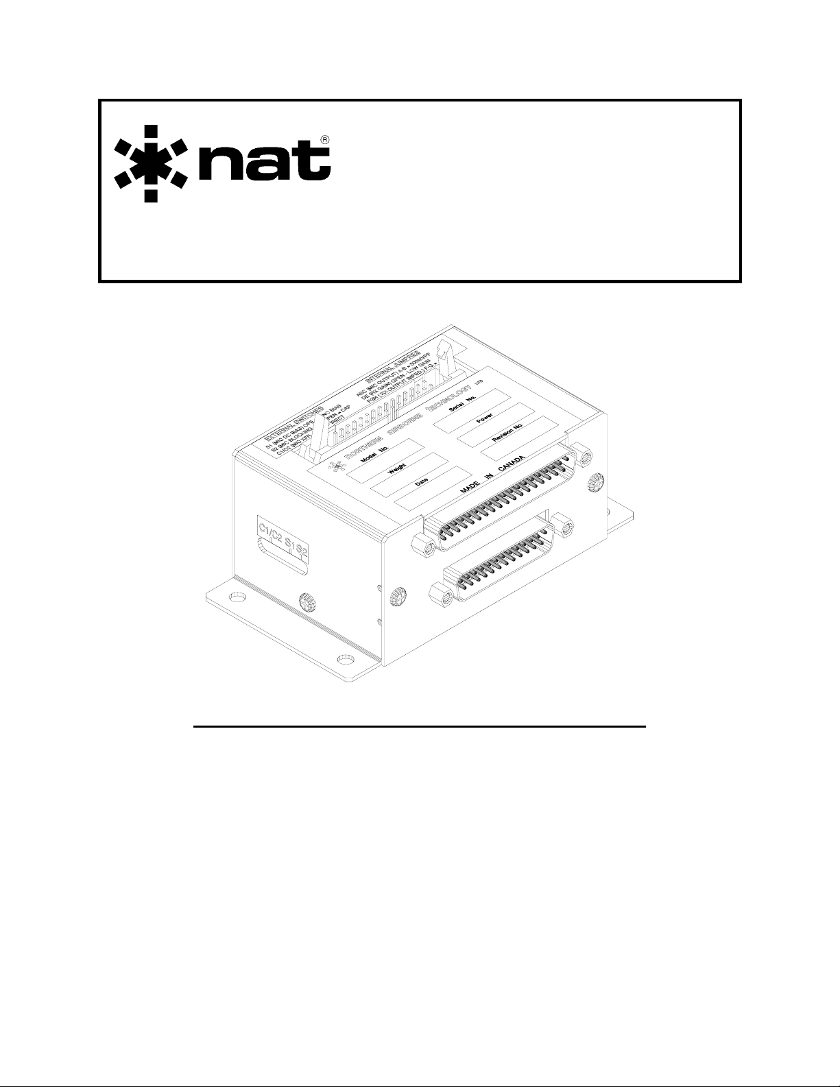
1.2 Purpose of Equipment
The MI34 is a bulkhead mounted interface unit specifically designed to allow NAT MT
series, Midland Syn-Tech I, or Midland Syn-Tech XTR mobile radios to be used in
aircraft audio systems.
1.3 Design Features
The MI34 provides internal microphone excitation, adjustable sidetone generation and a
floating output for the radio. It also provides a simple interconnect interface between
the radio and a Tac/Com control head
A fully floating, adjustable Receive Audio amplifier is included.
The MI34 is operational from either 14 or 28 VDC aircraft supply.
All interconnect and relay contacts are gold plated. The relay is sealed, high vibration
rated (50g shock) and dry nitrogen filled.
The circuit boards are constructed of G10-FR (flame retardant) material, with solder
masks, reflowed tin plating, and environmental post-coat.
Nov 20, 2003 Page 1-1
ENG-FORM: 800-0105.DOT
PROPRIETARY AND CONFIDENTIAL TO NORTHERN AIRBORNE TECHNOLOGY LTD.
Page 10

MI34 Mobile Interface Manual SM29 Rev. 4.00
1.4 Specifications
1.4.1 Electrical Specifications
Power +12 to 18 VDC at 160 mA max.
+20 to 33 VDC at 160 mA.
(Selected by appropriate pin)
Case is internally grounded.
Logic Ground seeking input for keyline (TX)
Outputs a DPDT set of uncommitted
contacts
Audio Receive (RX) input 2V typ. at 8 -100Ω
adjustable.
Outputs on 600Ω line (floating) with
200mW minimum at 150/600Ω
Microphone interface accepts all types,
and outputs either high or low level
signals, with or without excitation.
1.4.2 Physical Specifications
Height 1.725"
Length 4.50"
Width 2.40"
Weight 8 ounces (230 grams)
Mounting Bulkhead attachment
1.4.3 Environmental Specifications
Temperature -40 to +70°C
Altitude 15,000' max.
Humidity 95% Noncondensing
Shock 12g (any axis)
End of Section 1.0
Page 1-2 Nov 20, 2003
ENG-FORM: 800-0105.DOT
PROPRIETARY AND CONFIDENTIAL TO NORTHERN AIRBORNE TECHNOLOGY LTD.
Page 11

SM29 Rev. 4.00 MI34 Mobile Interface Manual
Section 2.0 Installation
2.1 Introduction
Information in this section consists of: unpacking and inspection procedures, installation
procedures, post-installation checks, and installation drawings.
2.2 Unpacking and Inspection
Unpack the equipment carefully and locate the warranty card. Inspect the unit visually
for damage due to shipping and report all such claims immediately to the carrier
involved. Note that each unit should have the following:
- MI34 Mobile Interface
- Warranty Card
- Release certification
Verify that all items are present before proceeding and report any shortage immediately
to your supplier.
2.2.1 Warranty
Complete the warranty card information and send it to NAT when the installation is
complete. If you fail to complete the warranty card, the warranty will be activated on
date of shipment from NAT.
Note: An appropriately rated facility, e.g. Certified Aircraft Repair Station, must install
this equipment in accordance with applicable regulations. NAT Ltd’s warranty is
not valid unless the equipment is installed by an authorized NAT Dealer. Failure
to follow any of the installation instructions, or installation by a non-certified
individual or agency will void the warranty, and may result in a non-airworthy
installation.
2.3 Installation Procedures
2.3.1 Warnings
Do not bundle any lines from this unit with transmitter coax lines. Do not bundle any
logic, audio, or DC power lines from this unit with 400 Hz synchro wiring or AC power
lines. Do not position this unit next to any device with a strong alternating magnetic field
such as a inverter, or significant audio interference will result.
Nov 30, 2003 Page 2-1
ENG-FORM: 805-0109.DOT Amendment # 1 Jan 10, 2007
CONFIDENTIAL AND PROPRIETARY TO NORTHERN AIRBORNE TECHNOLOGY LTD.
Page 12

MI34 Mobile Interface Manual SM29 Rev. 4.00
2.3.2 Cautions
In all installations, use shielded cable exactly as shown, and ground as indicated.
Significant problems may result from not following these guidelines.
All audio installations can be degraded by incorrect wiring and shielding, and may result
in abnormal cross-talk, hum, and ground-loop noise.
2.3.3 Notes
For Midland SynTech XTR radios, the 34-pin ribbon cable assembly may need to be reterminated to match the pin allocations shown on drawing MI34\403-2 and drawing
MI34\403-3.
2.3.4 Cabling and Wiring
All unshielded wire shall be selected in accordance with AC43.13-1B Change 1,
Paragraphs 11-76 through 11-78. Wire types should be to MIL-W-22759 as specified in
AC43.13-1B Change 1, Paragraphs 11-85, 11-86, and listed in Table 11-11. For
shielded wire applications, use Tefzel MIL-C-27500 shielded wire with solder sleeves
(for shield terminations) to make the most compact and easily terminated interconnect.
Follow the wiring diagrams in Section 2.6 as required.
Allow 3 inches from the end of the wire to the shield termination to allow the hood to be
easily installed. Note that the hood is a ‘clamshell’ hood, and is installed after the wiring
is complete.
All wiring should be at least 24 AWG, except power and ground lines, which should be
at least 22 AWG. Ensure that all ground connections are clean and well secured.
2.3.5 Post-Installation Checks
If any preset requires adjustment, be sure this is carried out before the aircraft leaves,
and that the unit and its mating connector are secured before departure. Make all
required log book entries, electrical load, weight and balance amendments and other
paperwork as required by your local regulatory agency.
WARNING:
High volume settings can cause hearing damage.
Set the headset volume control to the minimum volume
setting prior to conducting audio tests, and slowly increase
the headset volume level to a comfortable listening level.
With the MI34 disconnected from its mating connector, check pin 1 of J101 for +28 VDC
(or +14 VDC on pin 2) relative to ground and check pin 14 for continuity to ground
(below 0.5 Ω). Do not attach the MI34 until these conditions are met.
Page 2-2 Nov 30, 2003
ENG-FORM: 805-0109.DOT Amendment # 1 Jan 10, 2007
CONFIDENTIAL AND PROPRIETARY TO NORTHERN AIRBORNE TECHNOLOGY LTD.
Page 13

SM29 Rev. 4.00 MI34 Mobile Interface Manual
Power up the aircraft's system with the MI34 installed, and confirm that the radio is
operating properly. Adjust the receive (RX), sidetone (S/T) and microphone (MIC)
levels as required. Be sure the internal jumpers and switches are correctly set. Refer
to Section 3.2 for switch and jumper default positions.
If difficulty is encountered, check interconnect or Mic level adjustments and switches.
Use of a service monitor (IFR 1200S or similar) is very beneficial in setting up the radio
to ensure correct modulation and low distortion.
Upon satisfactory completion of all performance checks, make the required log
entries and complete the necessary Regulatory Agency paperwork before
releasing the aircraft for service.
2.4 Continued Airworthiness
Maintenance of the MI34 is ‘on condition’ only. Periodic maintenance of this product is
not required.
2.5 Accessories Required But Not Supplied
Installation kit p/n MI34-IKC (crimp) is required to complete the installation. The kit
consists of the following:
Quantity Description NAT Part #
1 D-min 25-Pin Female Crimp Installation Kit D25SL-IKC
1 D-min 37-Pin Female Crimp Installation Kit D37SL-IKC
1 34-Pin IDC Connector 20-05-034
NAT Part #: D25SL-IKC consists of:
Quantity Description NAT Part #
1 D-min 25 Socket Housing 20-21-025
25 MS Crimp Socket 20-26-901
1* Jack Screw Set 20-27-002
1* Lock Clip Set 20-27-004
1 25-Pin Connector Hood 20-29-026
NAT Part #: D37SL-IKC consists of:
Quantity Description NAT Part #
1 D-min 37 Socket Housing 20-21-037
37 MS Crimp Socket 20-26-901
1* Jack Screw Set 20-27-002
1* Lock Clip Set 20-27-004
1 37 Pin Connector Hood 20-29-038
* Use as required.
Note: Ensure proper orientation of the 34-Pin IDC connector before crimping. Refer to
the appropriate installation diagram for Midland Radio installation.
Nov 30, 2003 Page 2-3
ENG-FORM: 805-0109.DOT Amendment # 1 Jan 10, 2007
CONFIDENTIAL AND PROPRIETARY TO NORTHERN AIRBORNE TECHNOLOGY LTD.
Page 14

MI34 Mobile Interface Manual SM29 Rev. 4.00
2.6 Installation Drawings
DRAWING REV. DESCRIPTION TYPE
MI34\403-1 1.10 Tac/Com C/H, MT Radio, MI34, VR28 (MT Series)
MI34\403-2 1.20 Tac/Com C/H, MT Radio, MI34, VR28
MI34\403-3 1.10 Tac/Com C/H, MT Radio, MI34, VR28, DF
MI34\405-1 - Midland Syn-Tech XTR or NAT MT/XTR Series
MI34\000\922-0 1.00 Mobile Interface
Mechanical Installation
Interconnect
Connector Map
Connector Map
Connector Map
Section 2.0 ends after these Drawings
Page 2-4 Nov 30, 2003
ENG-FORM: 805-0109.DOT Amendment # 1 Jan 10, 2007
CONFIDENTIAL AND PROPRIETARY TO NORTHERN AIRBORNE TECHNOLOGY LTD.
Page 15

Confidential and Proprietary to NAT
Page 16

Page 17

Confidential and Proprietary to NAT
Page 18

Page 19

Confidential and Proprietary to NAT
Page 20

Page 21

Page 22

Page 23

Confidential and Proprietary to NAT
Page 24

Page 25

SM29 Rev. 4.00 MI34 Mobile Interface Manual
Section 3.0 Operation
3.1 General
The operation of the MI34 is generally as part of a NAT system including a Tac/Com
control head and NAT MT series (Midland Syn-Tech I) or NAT MT/XTR series (Midland
Syn-Tech XTR) radio.
The MI34 provides a method of coupling the radios into the aircraft audio system. It can
provide the excitation needed for standard aircraft microphones and can output the mic
signal through a floating transformer winding to eliminate any ground loop or polarity
problems. The microphone signal is also used to generate adjustable artificial sidetone
which is echoed back to the audio system on the receive line. Receive Audio interface
is provided with level adjustments and floating connections.
In normal use the operation is completely transparent to the user.
3.2 Configuration
The units are normally shipped from NAT with the C1/C2 switch in the C1 position. This
bypasses the mic coupling transformer output and the mic is wired direct through the
MI34. The S1 switch is set in the 'ON' position providing internal mic bias, and the S2
switch is set to 'OFF' allowing C114 (DC blocking capacitor) to be in series in the MIC HI
audio line. With the C1/C2 switch in the C1 position, the Microphone (mic) adjustment
(R109) is taken out of the circuit and has no effect.
The Receive Audio (RX) level (R112) is set to 200 mW into 600Ω with a standard RX
signal of 2.5 Vrms.
The Sidetone (S/T) level (R104) is set to 25 mW into 600Ω with a standard mic signal
of 250 mVrms.
End of section 3.0
Nov 20, 2003 Page 3-1
ENG-FORM: 806-0104.DOT
PROPRIETARY AND CONFIDENTIAL TO NORTHERN AIRBORNE TECHNOLOGY LTD.
Page 26

 Loading...