

Page 1
Installation and Operation Manual
MB01-001
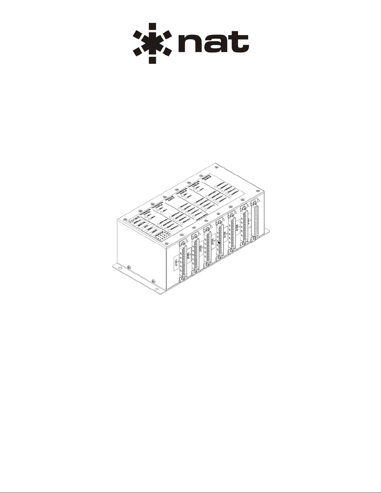
Matching Box
SM72
ISSUE 4.01
Northern Airborne Technology Ltd.
1925 Kirschner Road
Kelowna, BC, Canada.
V1Y 4N7
Telephone (250) 763-2232
Facsimile (250) 762-3374
Issued on the authority of Northern Airborne Technology Ltd.
Copyright 2005
Page 2
MB01-001 Matching Box
SM72 Installation and Operation Manual
Prepared By: Checked By: Approved By:
The status of this installation and operation manual is controlled by issue shown on the title page. The
status of each section is controlled by revision shown in the footer of each page. All revisions affecting
sections of this manual have been incorporated into the latest issue.
ISSUE/REVISION RECORD
Manual Issue
Number
Section
Revision Number
Revision Description Issue Date
4.01 Section 1 Rev: 1.00
Updated to current format. Apr 3, 2009
Section 2 Rev: 1.00
Section 3 Rev: 1.00
Installation and Operation Manual Page ii
ENG-FORM: 820-0114.DOT
CONFIDENTIAL AND PROPRIETARY TO NORTHERN AIR BORNE TECHNOLOGY LTD.
Page 3

MB01-001 Matching Box
SM72 Installation and Operation Manual
Table of Contents
Section Title Page
1. Description
1.1 Introduction 1-1
1.2 Product Description 1-1
1.3 Design Features 1-1
1.4 Specifications 1-1
1.4.1 Electrical Specifications 1-1
1.4.2 Physical Specifications 1-2
1.4.3 Environmental Specifications 1-2
2. Installation
2.1 Introduction 2-1
2.2 Unpacking and Inspection 2-1
2.2.1 Warranty 2-1
2.3 Continued Airworthiness 2-1
2.4 Installation Procedures 2-1
2.4.1 Warnings 2-1
2.4.2 Cautions 2-2
2.4.3 Cabling and Wiring 2-2
2.4.4 Post-Installation Checks 2-2
2.5 Adjustments and Connections 2-3
2.6 Installation Drawings 2-4
3. Operation
3.1 Introduction 3-1
3.2 General Information 3-1
3.3 Controls and Indicators 3-1
Installation and Operation Manual Page iii
ENG-FORM: 820-0114.DOT
CONFIDENTIAL AND PROPRIETARY TO NORTHERN AIR BORNE TECHNOLOGY LTD.
Page 4

MB01-001Matching Box
SM72 Installation and Operation Manual
Section 1 Description
1.1 Introduction
Information in this section consists of product description, design features and specifications for the
MB01-001Matching Box. All derivative product information shall be contained in the applicable manual
supplement, which may be obtained from NAT as required.
Review all notes, warnings and cautions.
1.2 Product Description
The MB01-001 is a remote mounted audio level matching unit for 8 transceivers and 10 receivers. It
provides 8 floating key signals and is capable of providing unamplified artificial sidetone. The unit also
provides a diode OR’ed DF Mute signal when any of the transceivers are keyed.
1.3 Design Features
The MB01-001 is made up of 8 subassemblies: 2 ‘Receiver’ subassemblies, 4 ‘Transceiver’
subassemblies, one Test subassembly and one Backplane subassembly. Each ‘Receiver’ subassembly
supports 5 receivers and each ‘Transceiver’ subassembly supports two transceivers. The Test
subassembly connector provides the installing agency access to all microphone and receive signals while
all the equipment is connected. This allows proper level adjustments to be made while all inputs and
outputs are loaded. The MB01-001 supports real sidetone, dedicated sidetone inputs (with 6dB of
attenuation) and can generate unamplified artificial sidetone. All connectors are labeled to assist with
proper connection to the airframe wiring.
1.4 Specifications
1.4.1 Electrical Specifications
Input Signals
Quantity 18 Receive inputs
8 Microphone inputs
8 Sidetone inputs
Audio Level 4.9 Vrms nominal for receive inputs
4.9 Vrms nominal for sidetone inputs
1 Vrms nominal for microphone inputs
Impedance 350 Ω ±10% max for microphone inputs
600 Ω ±10% for receive inputs
1000 Ω ±10% for sidetone inputs
Circuitry Type All are balanced inputs
Keylines PTT <30 mA input current
Section 1 Rev: 1.00 Issue 4 Page 1-1
ENG-FORM: 800-0114.DOT
CONFIDENTIAL AND PROPRIETARY TO NORTHERN AIR BORNE TECHNOLOGY LTD.
Page 5

MB01-001Matching Box
SM72 Installation and Operation Manual
Output Signals
Quantity 18 Receive outputs
8 Microphone outputs
Audio level 2 Vrms nominal for receive outputs
2 Vrms nominal for sidetone outputs
0.5 Vrms nominal for microphone outputs
Impedance 600 Ω ±10% for microphone outputs
375 Ω ±10% for receive outputs
Distortion <10% THD @ Rated power output
Circuitry Type All are balanced outputs
Keylines Floating or direct PTT
≤0.5 A at 30 Vdc Resistive handling current
≤0.1 A at 30 Vdc Inductive handling current
DF Mute Keylines are diode OR’ed and produce a summed output on
each of the receiver cards
1.4.2 Physical Specifications
Height 3.15" (80.1mm)
Depth 4.00" (101.6 mm)
Width 8.11" (206.0 mm)
Weight 2.5 lbs
Mounting Bulkhead mount with four 10-32 screws
Material/Finish Chassis & cover are 5052-H32 brushed aluminum with chromate
conversion finish
Connectors Six male 37-pin D-submin connectors with Positronics V5 locking
tabs, and one female 62 pin high density D-submin connector
with Positronics V5 locking tabs
1.4.3 Environmental Specifications
Temperature
Operating -40° C to +70° C DO-160C Cat. B4
Survival -55° C to +85° C
Altitude 25,000 ft. Max.
Section 1 Rev: 1.00 Issue 4 Page 1-2
ENG-FORM: 800-0114.DOT
CONFIDENTIAL AND PROPRIETARY TO NORTHERN AIR BORNE TECHNOLOGY LTD.
Page 6

MB01-001Matching Box
SM72 Installation and Operation Manual
Shock DO-160C Cat N Operational Shock only
Qualification DO-160C as contracted
Section 1 ends
Section 1 Rev: 1.00 Issue 4 Page 1-3
ENG-FORM: 800-0114.DOT
CONFIDENTIAL AND PROPRIETARY TO NORTHERN AIR BORNE TECHNOLOGY LTD.
Page 7

MB01-001Matching Box
SM72 Installation and Operation Manual
Section 2 Installation
2.1 Introduction
Information in this section consists of unpacking and inspection procedures, installation procedure s, po stinstallation checks and installation drawings for the MB01-001Matching Box.
Review all notes, warnings and cautions.
2.2 Unpacking and Inspection
Unpack the equipment carefully and locate the warranty card. Inspect the unit visually for damage due to
shipping and report all such claims immediately to the carrier involved. Check that all items listed below
are present before proceeding and report any shortage immediately to your supplier:
- Warranty Card
- Certificate of Conformity or Release Certification
2.2.1 Warranty
All Northern Airborne Technology Ltd. products are warranted for 2 years from date of installation by an
authorized NAT dealer, to be free of defects in workmanship or performance. This warranty covers all
materials and labour, but is exclusive of any transport to deliver the defective unit to and from NAT or its
designated warranty repair center, or any labour to remove or re-install the defective unit in the aircraft.
Contact NAT for any questions regarding this warranty, its applicability to your units and/or for return
authorization. NAT is the final arbitrator concerning warranty administration. Units which have been
physically damaged, burned, immersed in water or otherwise abused beyond the scope of normal use will
not be considered for warranty. WARRANTY IS VOID UNLESS THE PRODUCT IS INSTALLED BY AN
AUTHORIZED NAT DEALER. Product for which a warranty card is not returned shall be warranted from
date of manufacture.
2.3 Continued Airworthiness
Maintenance of the MB01-001Matching Box is ‘on condition’ only. Periodic maintenance of this product is
not required.
2.4 Installation Procedures
2.4.1 Warnings
WARNING:
High volume settings can cause hearing damage.
Set the headset volume control to the minimum volume setting prior to
conducting tests, and slowly increase the headset volume to a
comfortable listening level.
Section 2 Rev: 1.00 Issue 4 Page 2-1
ENG-FORM: 805-0117.DOT
CONFIDENTIAL AND PROPRIETARY TO NORTHERN AIR BORNE TECHNOLOGY LTD.
Page 8

MB01-001Matching Box
SM72 Installation and Operation Manual
2.4.2 Cautions
CAUTION:
All audio installations can be seriously degraded by incorrect wiring and
shielding, and may result in abnormal cross-talk, hum and ground-loop noise.
Be especially careful with all microphone wiring and tie line wiring, as these
lines carry the lowest level signals in the aircraft.
2.4.3 Cabling and Wiring
All wire shall be selected in accordance with the original aircraft manufacturer's Maintenance Instructions
or AC43.13-1B Change 1, Paragraphs 11-76 through 11-78. Unshielded wire types shall qualify to
MIL-W-22759 as specified in AC43.13-1B Change 1, Paragraphs 11-85, 11-86, and listed in Table 11-11.
For shielded wire applications, use Tefzel MIL-C-27500 shielded wire with solde r sleeve s (fo r shield
terminations) to make the most compact and easily terminated interconnect. Follow the connector map in
Section 2.6 as required.
Allow 3" from the end of the shielded wiring to the shield termination to allow the connector hood to be
easily installed. Reference the interconnect drawing in Section 2.6 for shield termination details. Note that
the hood is a "clamshell" hood, and is installed after the wiring is complete. Aircraft harnessing shall
permit the unit to be removed from the panel for easy access to all side adjustments. Do NOT mount the
unit until all adjustments have been performed.
Maintain wire segregation and route wiring in accordance with the original aircraft manufacturers
Maintenance Instructions.
Unless otherwise noted, all wiring shall be a minimum of 22 AWG, except power and ground lines, which
shall be a minimum of 20 AWG. Reference the Interconnect drawing for additional specifications. Check
that the ground connection is clean and well secured, and that it shares no path with any electrically noisy
aircraft accessories such as blowers, turn and bank instruments or similar loads. Power to this unit must
be supplied from a separate circuit breaker or fuse (fast blow), and not attached to any other circuit
breaker without additional protection. Verify that the selected circuit breaker size and wire gauge are
adequate for the installation using the techniques specified in AC43.13-1B Change 1, Paragraphs 11-47
through 11-51 and 11-66 through 11-69.
2.4.4 Post-Installation Checks
2.4.4.1 Voltage/Resistance Checks
Do not attach the MB01-001 until the following conditions are met.
Check the following for Transceiver Subassemblies:
a) Check P101, pin <10> for continuity to ground (less than 0.5Ω).
b) Check P102, pin <10> for continuity to ground (less than 0.5Ω).
c) Check P104, pin <10> for continuity to ground (less than 0.5Ω).
d) Check P105, pin <10> for continuity to ground (less than 0.5Ω).
Section 2 Rev: 1.00 Issue 4 Page 2-2
ENG-FORM: 805-0117.DOT
CONFIDENTIAL AND PROPRIETARY TO NORTHERN AIR BORNE TECHNOLOGY LTD.
Page 9

MB01-001Matching Box
SM72 Installation and Operation Manual
Check the following for Receiver Subassemblies:
a) Check P103, pin <4> for continuity to ground (less than 0.5Ω).
b) Check P106, pin <4> for continuity to ground (less than 0.5Ω).
Check the following for Test Subassembly:
a) Check P107, pin <1> for continuity to ground (less than 0.5Ω).
2.4.4.2 Power On Checks
Power up the aircraft’s systems and confirm normal operation of all functions of the MB01-001. Refer to
Section 3 (Operation) for specific operational details.
a) Check preset adjustments are completed before aircraft departure.
Upon satisfactory completion of all performance checks, make all required log book entries, electrical
load, weight and balance amendments and other documentation as required by your local regulatory
agency before releasing the aircraft for service.
2.5 Adjustments and Connections
The unit is shipped from the factory with all internal adjustments set to the normal test levels. Once
installed in the aircraft, it may be desirable to change some of these settings to best suit the local
operating environment. The internal adjustments are located through the top cover. See Figure 1.
Figure 1: Internal Adjustments
All microphone, receive and artificial sidetone adjustments are 10-turn trimpots. The dedicated sidetone
inputs are not adjustable.
Section 2 Rev: 1.00 Issue 4 Page 2-3
ENG-FORM: 805-0117.DOT
CONFIDENTIAL AND PROPRIETARY TO NORTHERN AIR BORNE TECHNOLOGY LTD.
Page 10

MB01-001Matching Box
SM72 Installation and Operation Manual
2.6 Installation Drawings
DOCUMENT REV. DESCRIPTION TYPE SERIAL NO.
MB01-001
MB01\001\922-0 1.00 Matching Box Mechanical Installation 1011 and up
MB01-1
MB01-1\403-0 1.00 Transceiver Subassembly Interconnect 1011 and up
MB01-1\405-0 1.00 Transceiver Subassembly Connector Map 1011 and up
MB01-2
MB01-2\403-0 1.00 Receiver Subassembly Interconnect 1011 and up
MB01-2\405-0 1.00 Receiver Subassembly Connector Map 1011 and up
MB01-3
MB01-3\405-0 1.00 Test Subassembly Connector Map 1011 and up
Section 2 ends following the above documents
Section 2 Rev: 1.00 Issue 4 Page 2-4
ENG-FORM: 805-0117.DOT
CONFIDENTIAL AND PROPRIETARY TO NORTHERN AIR BORNE TECHNOLOGY LTD.
Page 11

Page 12

Page 13

Page 14

Page 15

Page 16

Page 17

MB01-001Matching Box
SM72 Installation and Operation Manual
Section 3 Operation
3.1 Introduction
Information in this section consists of functional and operational procedures for the MB01-001Matching
Box.
3.2 General Information
The MB01-001 is a remote mounted audio level matching unit for 8 transceivers and 10 receivers. It
provides 8 floating key signals and is capable of providing unamplified artificial sidetone. The unit also
provides a diode OR’ed DF Mute signal when any of the transceivers are keyed.
3.3 Controls and Indicators
The MB01-001 has no normal user operational aspects. During installation, or if the unit has been
exchanged, it may be a requirement to change internal adjustments. This should be done ONLY BY
FULLY QUALIFIED PERSONNEL.
Section 3 ends
Section 3 Rev: 1.00 Issue 4 Page 3-1
ENG-FORM: 806-0113.DOT
CONFIDENTIAL AND PROPRIETARY TO NORTHERN AIR BORNE TECHNOLOGY LTD.
 Loading...