

Page 1
Part of
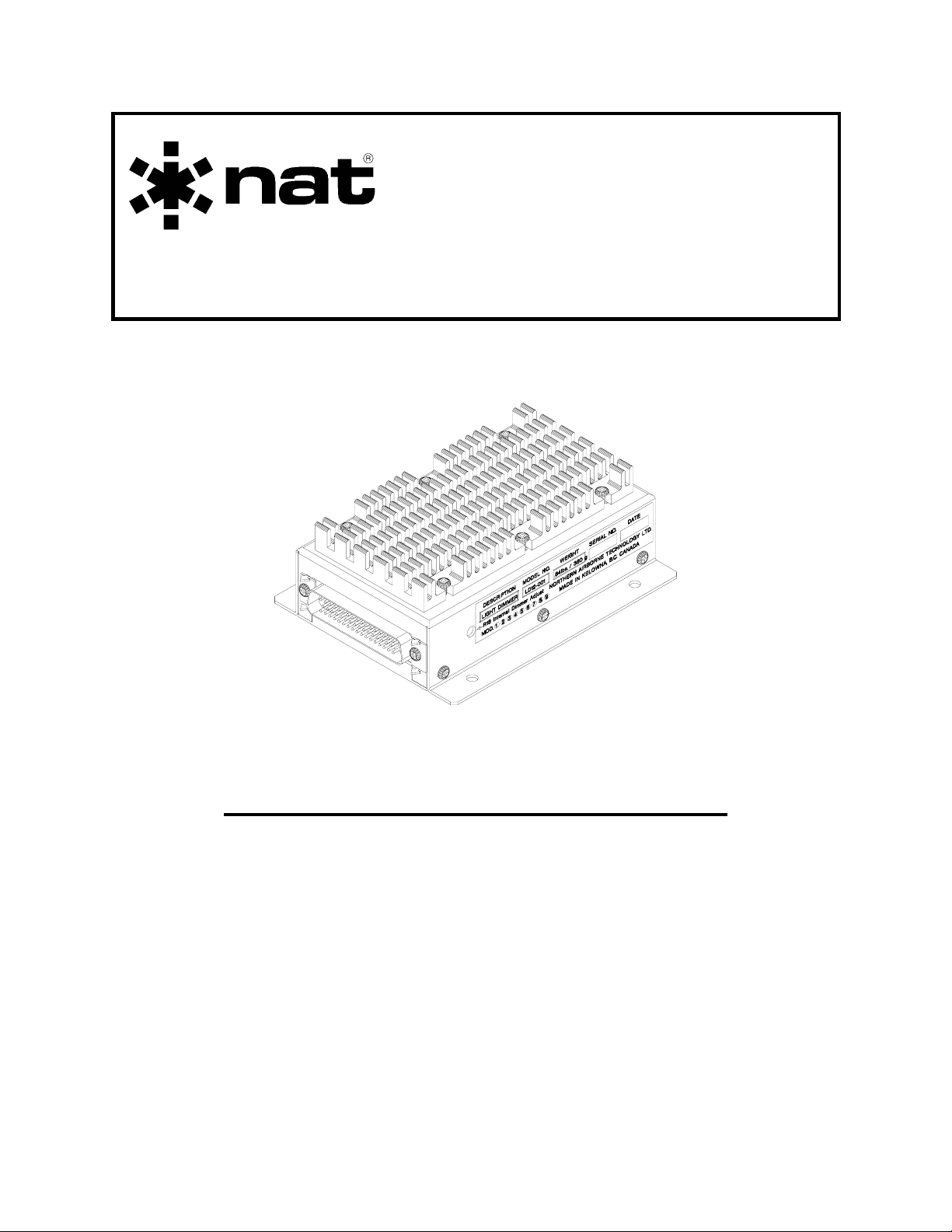
SM15
LD12
Lamp Dimmer
INSTALLATION and OPERATION MANUAL
REV 4.00 November 21, 2003
Northern Airborne Technology Ltd.
1925 Kirschner Road
Kelowna BC, Canada
V1Y 4N7
Telephone (250) 763-2232
Facsimile (250) 762-3374
Copyright 2003 by Northern Airborne Technology
CONFIDENTIAL AND PROPRIETARY TO NORTHERN AIRBORNE TECHNOLOGY LTD.
Page 2

Page 3

SM15 Rev 4.00 LD12 Lamp Dimmer Manual
Periodically NAT will release manual amendments. In order to maintain the most
accurate and up to date manual these amendments should be carried out immediately
upon receipt and recorded on the following amendment record.
AMENDMENT RECORD
Amendment
Number
Amendment
Date
Section(s)
Changed
Date
Entered
Entered By
Insert any Amendment Instruction sheets after this page.
Nov 21, 2003 Page ii
ENG-FORM: 820-0109.DOT
CONFIDENTIAL AND PROPRIETARY TO NORTHERN AIRBORNE TECHNOLOGY LTD.
Page 4

Page 5

SM15 Rev 4.00 LD12 Lamp Dimmer Manual
Table of Contents
Section Title Page
1.0 Description
1.1 Introduction 1-1
1.2 Purpose of Equipment 1-1
1.3 Features 1-1
1.4 Specifications 1-1
1.4.1 Electrical Specifications 1-1
1.4.2 Physical Specifications 1-2
1.4.3 Environmental Specifications 1-3
2.0 Installation
2.1 Introduction 2-1
2.2 Unpacking and Inspection 2-1
2.3 Installation Procedures 2-1
2.3.1 Warnings 2-1
2.3.2 Cautions 2-1
2.3.3 Notes 2-2
2.3.4 Cabling and Wiring 2-2
2.3.5 Installation Variations 2-2
2.3.6 Optional Dimmer Adjustment 2-3
2.3.7 Optional Emergency Bypass Switch 2-3
2.3.8 Post-Installation Checks 2-3
2.4 Continued Airworthiness 2-4
2.5 Installation Drawings 2-4
3.0 Operation
3.1 Introduction 3-1
3.2 Operation 3-1
Nov 21, 2003 Page iii
ENG-FORM: 820-0109.DOT
CONFIDENTIAL AND PROPRIETARY TO NORTHERN AIRBORNE TECHNOLOGY LTD.
Page 6

Page 7

SM15 Rev. 4.00 LD12 Lamp Dimmer Manual
Section 1.0 Description
1.1 Introduction
This manual contains information on the LD12 Lamp Dimmer.
Information in this section consists of purpose of equipment, features and specifications.
1.2 Purpose of Equipment
The LD12 is a remote mounted light dimmer module, designed for complicated
annunciator requirements in Loran / GPS systems. The unit is capable of controlling 12
independent lamps with full test function. In its basic mode of operation, the LD12 can
be used as a bulk lamp dimmer, outputting up to 1 amp of current. The LD12 unit can
be easily interfaced with all NAT RS-series remote switch products used in Loran / GPS
installations.
1.3 Features
Internal logic is provided to interface to both the floating lamp connections of the PB08,
and annunciators triggered by a ground output. An adjustable lamp dimmer is provided
to drive twelve separate 28 Vdc/50 mA lamp lines.
The dimmer may be operated in the preset mode (typically set in the 12-24 V range), or
as an adjustable dimmer via an external control. A single switch can be used to select
day, night, and lamp test functions.
The day operation mode also provides regulated 24 Vdc for all lamps, to prevent early
lamp failure and internal lamp blackening from excessive voltage.
All interconnect and relay contacts are gold plated. Relays are sealed, high vibration
rated (50 g shock), dry nitrogen filled units.
Circuit boards are constructed of G10-FR (flame retardant) material, with solder masks,
reflowed tin plating, and environmental post-coating.
Nov 21, 2003 Page 1-1
ENG-FORM: 800-0106.DOT
CONFIDENTIAL AND PROPRIETARY TO NORTHERN AIRBORNE TECHNOLOGY LTD.
Page 8

LD12 Lamp Dimmer Manual SM15 Rev. 4.00
1.4 Specifications
1.4.1 Electrical Specifications
Input Power +24.8 Vdc to +30 Vdc, +27.5 Vdc nominal
(reverse and over voltage protection)
Input Current 50 mA idle (2 A max.)
Inputs:
Test Keyline Active low input. Grounding this pin will cause
all lamps to illuminate at full brightness. This
feature allows the user to check for faulty
filaments.
Dimmer Active low input. Grounding this pin will cause
the internal preset dimmer voltage to be
supplied to all lamps.
Dimmer GND Provides a convenient ground return for the
dimmer controls.
Lamp Pwr In Direct connection to internal lamp bus.
Lamp Keys Active low keyline. Grounding this pin will
cause the selected lamp to illuminate. Current
drawn will depend on type of lamp used in
circuit. Pin should be left open when unused.
Outputs
Lamp Outputs 0 mA to 50 mA of current to 2 floating lamp
circuits and 10 ground keyed circuits for system
annunciators. Recommended lamps: Type 327,
387 or 388 for 28V operation @ 40 mA each.
Dimmer Out Direct connection to dimmer circuit output.
Provides up to 1 A of current.
Page 1-2 Nov 21,2003
ENG-FORM: 800-0106.DOT
CONFIDENTIAL AND PROPRIETARY TO NORTHERN AIRBORNE TECHNOLOGY LTD.
Page 9

SM15 Rev. 4.00 LD12 Lamp Dimmer Manual
1.4.2 Physical Specifications
Height 1.75 inches (44.5 mm)
Length 5.00 inches (127.0 mm)
Width 3.95 inches (100.3 mm)
Weight 380 g. (0.84 lbs.) Max.
Mounting Bulkhead attachment ( 4 x 10-32 screws)
1.4.3 Environmental Specifications
Operating Temperature -15° C to +70° C
Storage Temperature -55° C to +85° C
Altitude 50,000 ft
Humidity 95% Non-condensing Cat. A
Vibration DO-160C, Cat. B,M,N
End of section 1.0
Nov 21, 2003 Page 1-3
ENG-FORM: 800-0106.DOT
CONFIDENTIAL AND PROPRIETARY TO NORTHERN AIRBORNE TECHNOLOGY LTD.
Page 10

Page 11

SM15 Rev. 4.00 LD12 Lamp Dimmer Manual
Section 2.0 Installation
2.1 Introduction
Information in this section consists of: unpacking and inspection procedures, installation
procedures, post-installation checks, and installation drawings.
2.2 Unpacking and Inspection
Unpack the equipment carefully and locate the warranty card. Inspect the unit visually
for damage due to shipping and report all such claims immediately to the carrier
involved. Note that each unit should have the following:
- LD12 Lamp Dimmer
- Warranty Card
- Release certification
Verify that all items are present before proceeding and report any shortage immediately
to your supplier.
Complete the warranty card information and send it to NAT when the installation is
complete. If you fail to complete the warranty card, the warranty will be activated on
date of shipment from NAT.
2.3 Installation Procedures
2.3.1 Warnings
Do not bundle any lines from this unit with transmitter coax lines. Do not bundle any
logic or DC power lines from this unit with 400 Hz synchro wiring or AC power lines. Do
not position this unit next to any device with a strong alternating magnetic field such as
an inverter, motor or blower.
2.3.2 Cautions
Do not install the LD12 without making a suitable amendment to the flight manual
indicating how the NAV annunciation and dimming/ test functions have been
implemented in the aircraft.
Nov 21, 2003 Page 2-1
ENG-FORM: 805-0104.DOT
CONFIDENTIAL AND PROPRIETARY TO NORTHERN AIRBORNE TECHNOLOGY LTD.
Page 12

LD12 Lamp Dimmer Manual SM15 Rev. 4.00
2.3.3 Notes
In order to minimize wiring, the unit should be located close to the annunciators it will be
dimming. It should not be mounted near hot air paths, as it needs to dissipate
substantial heat.
2.3.4 Cable and Wiring
Use Tefzel Mil-M-27500, Mil-M-22759 or Mil-M-81044 single conductor and shielded
wire with solder sleeves (for shield termination) to make the most compact and easy to
terminate interconnect. Follow the wiring diagrams provided in Section 2.4 as required.
Note that the hood is a "clamshell" hood and is installed after the wiring is complete.
Aircraft harnessing should permit the unit to be lowered from the panel for easy access
to all adjustments. DO NOT mount the unit until all adjustments have been carried out.
All wiring should be at least 22 AWG, except input power and ground connections which
should be 20 AWG. Ensure that the ground connection is clean and well secured and
that it shares no path with any electrically noisy aircraft accessories such as blowers,
turn and bank instruments or similar loads. To prevent system failure or inadequate
equipment protection, power to this system must be supplied from a separate breaker or
fuse (2 A) and not bundled to any other source.
2.3.5 Installation Variations
The normal installation of the LD12-001 uses a single toggle switch for the pilot's
control. This selects the following modes:
DIM Night flying lamp levels. Can be adjusted either at the panel
or inside the LD12-001.
NORM Day flying lamp levels (full brightness).
TEST All lamps ON (full brightness). Tests functionality of all
lamps.
The switch is a SPDT center-off toggle, spring loaded in the TEST position so that it will
return to the normal position when released. Alternately, the DIM function can be
selected by a separate switch, or tied into another switch function, and the lamp test can
be activated by a momentary pushbutton switch.
The DIM position can also have a level control connected in series with the switch, to
permit local adjustment of the night flying lamp level. The switch may also be integral
with the level control to conserve panel space.
Page 2-2 Nov 21, 2003
ENG-FORM: 805-0104.DOT
CONFIDENTIAL AND PROPRIETARY TO NORTHERN AIRBORNE TECHNOLOGY LTD.
Page 13

SM15 Rev. 4.00 LD12 Lamp Dimmer Manual
2.3.6 Optional Dimmer Adjustment
Inserting a 10 kΩ, 1/2 W linear taper potentiometer between the dimmer input and
ground will allow external adjustment of the dimming voltage. If using an external
adjustment, make sure internal trimpot is set for minimum voltage output (rotated fully
counterclockwise).
2.3.7 Optional Emergency Bypass Switch
This is an optional external SPST toggle switch; it can be used to route an external
voltage to the lamps if the dimmer should fail.
2.3.8 Post-Installation Checks
Before the unit is mounted, make all functional tests and trimpot adjustments. Be sure
the harness has enough clearance to permit the unit to be pulled out for re-adjustment,
if needed later.
2.3.8.1 Voltage/Resistance Checks
Do not attach the LD12 until these conditions are met.
a) At the airframe connector, check P1 pin 1 for +28 VDC relative to ground and
pin 34 for continuity to ground (below 0.5 ohms).
b) Ensure that no short circuits exist on any lamp line (lamp hi to lamp lo or to
ground), and that no press-to test lamp holders have been used. These can
cause the lamp line(s) to be shorted to ground, which may damage the internal
circuitry of the LD12.
2.3.8.2 System Checks
a) Install the LD12 and power up the ship’s systems. Select the TEST position on
the dimmer switch and check that all lamps are functioning.
b) Select the BRIGHT position on the dimmer switch; lamps that are activated
should be fully illuminated.
c) Select the DIM position on the dimmer switch and adjust the dimmer pot; the
active lamps should track the dimmer pot.
d) Make sure unit is securely fastened and that the connector locks are correctly
mated before any flight is attempted.
Nov 21, 2003 Page 2-3
ENG-FORM: 805-0104.DOT
CONFIDENTIAL AND PROPRIETARY TO NORTHERN AIRBORNE TECHNOLOGY LTD.
Page 14

LD12 Lamp Dimmer Manual SM15 Rev. 4.00
2.4 Continued Airworthiness
Maintenance of the LD12 Lamp Dimmer is ‘on condition’ only. Periodic maintenance of
this product is not required.
2.5 Installation Drawings
DRAWING REV. DESCRIPTION TYPE
LD12\001\403-0 1.00 Lamp Dimmer - External Dimming Interconnect
LD12\001\403-1 1.00 Lamp Dimmer with RS08 - External Dimming Interconnect
LD12\001\405-0 1.00 Lamp Dimmer Connector Map
LD12\001\922-0 1.01 Lamp Dimmer (Serial #’s 1001 – 1050) Mech Installation
LD12\001\922-0 1.10 Lamp Dimmer (Serial #’s 1051 and up) Mech Installation
Section 2.0 ends after these Drawings
Page 2-4 Nov 21, 2003
ENG-FORM: 805-0104.DOT
CONFIDENTIAL AND PROPRIETARY TO NORTHERN AIRBORNE TECHNOLOGY LTD.
Page 15

Confidential and Proprietary to NAT
Page 16

Page 17

Confidential and Proprietary to NAT
Confidential and Proprietary to NAT
Page 18

Page 19

Confidential and Proprietary to NAT
Page 20

Page 21

Confidential and Proprietary to NAT
Page 22

Page 23

Confidential and Proprietary to NAT
Page 24

Page 25

SM15 Rev. 4.00 LD12 Lamp Dimmer Manual
Section 3.0 Operation
3.1 Introduction
Information in this section consists of the functional and operational procedures for the
LD12 Lamp Dimmer.
3.2 Operation
The LD12 Lamp Dimmer has no normal user operational aspects. During
installation, or if the unit has been exchanged, it may be a requirement to change
internal adjustments. This should be done ONLY BY FULLY QUALIFIED PERSONNEL.
End of Section 3.0
Nov 21, 2003 Page 3-1
ENG-FORM: 806-0105.DOT
CONFIDENTIAL AND PROPRIETARY TO NORTHERN AIRBORNE TECHNOLOGY LTD.
Page 26

 Loading...