

Page 1
Part of
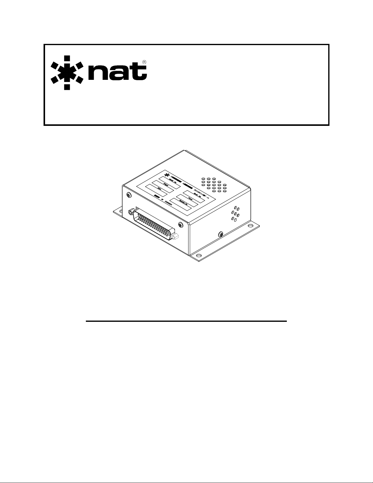
SM15
LD08
Lamp Dimmer Manual
INSTALLATION AND OPERATION MANUAL
REV 4.00 November 21, 2003
Northern Airborne Technology Ltd.
1925 Kirschner Road
Kelowna BC, Canada
V1Y 4N7
Telephone (250) 763-2232
Facsimile (250) 762-3374
Copyright 2003 by Northern Airborne Technology
CONFIDENTIAL AND PROPRIETARY TO NORTHERN AIRBORNE TECHNOLOGY LTD.
Page 2

Page 3

SM15 Rev 4.00 LD08 Lamp Dimmer Manual
Periodically NAT will release manual amendments. In order to maintain the most
accurate and up to date manual these amendments should be carried out immediately
upon receipt and recorded on the following amendment record.
AMENDMENT RECORD
Amendment
Number
Amendment
Date
Section(s)
Changed
Date
Entered
Entered By
Insert any Amendment Instruction sheets after this page.
Nov 21, 2003 Page ii
ENG-FORM: 820-0109.DOT
CONFIDENTIAL AND PROPRIETARY TO NORTHERN AIRBORNE TECHNOLOGY LTD.
Page 4

Page 5

SM15 Rev 4.00 LD08 Lamp Dimmer Manual
Table of Contents
Section Title Page
1.0 Description
1.1 Introduction 1-1
1.2 Purpose of Equipment 1-1
1.3 Features 1-1
1.4 Specifications 1-2
1.4.1 Electrical Specifications 1-2
1.4.2 Physical Specifications 1-2
1.4.3 Environmental Specifications 1-3
1.5 Unit Nomenclature 1-3
2.0 Installation
2.1 Introduction 2-1
2.2 Unpacking and Inspection 2-1
2.3 Installation Procedures 2-1
2.3.1 Warnings 2-1
2.3.2 Notes 2-1
2.3.3 Cable and Wiring 2-2
2.4 Installation Options 2-2
2.4.1 Optional Dimmer Adjustment 2-2
2.4.2 NORM/EMERG BYPASS Switch 2-3
2.5 Post-Installation Checks 2-3
2.5.1 Voltage/resistance checks 2-3
2.5.2 System Checks 2-3
2.6 Continued Airworthiness 2-3
2.7 Installation Drawings 2-3
3.0 Operation
3.1 General 3-1
3.2 Operation 3-1
Nov 21, 2003 Page iii
ENG-FORM: 820-0109.DOT
CONFIDENTIAL AND PROPRIETARY TO NORTHERN AIRBORNE TECHNOLOGY LTD.
Page 6

Page 7

SM15 Rev. 4.00 LD08 Lamp Dimmer Manual
Section 1.0 Description
1.1 Introduction
This manual contains information on the LD08 Lamp Dimmer.
Information in this section consists of purpose of equipment, features and specifications.
1.2 Purpose of Equipment
The LD08 is a bulkhead mounted dimming and lamp test unit, specifically designed to
handle the complex annunciator requirements of LORAN C/GPS systems sharing an
existing NAV system indicator.
The correct dimming and lamp test interface is provided for the RS08/PB08
combination, as well as six (6) additional discrete annunciators. This permits simple
integration of systems such as the Bendix/King Loran or Trimble GPS/Loran with the
nav switching functions of the RS08. It also provides central annunciation dimming
(day/night) selection and a central lamp test function, all on a single panel mounted
toggle switch. Optional interconnect permits adjustment of the annunciator dimming
with an external 10 kΩ potentiometer.
1.3 Features
Internal logic is provided to interface both the floating lamp connections of the PB08,
and annunciators triggered by a ground output. An adjustable lamp dimmer is provided
to drive eight separate 28 Vdc/40 mA lamp lines, each with individual short circuit
protection, surge limiting, and lamp test logic.
The dimmer may be operated in the preset mode (typically set in the 8-19 V range), or
as an adjustable dimmer via an external control. A single switch can be used to select
day, night, and lamp test functions.
The day operation mode also provides regulated 24 Vdc for all lamps, to prevent early
lamp failure and internal lamp blackening from excessive voltage.
All interconnect and relay contacts are gold plated. Relays are sealed, high vibration
rated (50 g shock), dry nitrogen filled units.
Circuit boards are constructed of G10-FR (flame retardant) material, with solder masks,
reflowed tin plating, and environmental post-coating.
Nov 21, 2003 Page 1-1
ENG-FORM: 800-0106.DOT
CONFIDENTIAL AND PROPRIETARY TO NORTHERN AIRBORNE TECHNOLOGY LTD.
Page 8

LD08 Lamp Dimmer Manual SM15 Rev. 4.00
1.4 Specifications
1.4.1 Electrical Specifications
Input Power +18 to 33 Vdc at 100 mA max. (excluding lamps)
Lamps Type 327/387 for 28 V (40 mA)
All lamp lines include ‘loop-through’ pins, to eliminate
the requirement for an external terminal block for
multiple connections
Logic Ground for lamp test
Ground for dimmer (or 10kΩ pot to ground)
Open for Day Operation (undimmed)
Annunciators 2 Floating circuits (For PB08/RS08)
6 Ground keyed circuits for system indicators
All short circuit protected
DIM OUT Direct connection to dimmer output, 320 mA max load
(8 ea. 40 mA lamps)
(Normally used for connection to RS08)
DIM IN Direct connection to internal lamp bus
1.4. 2 Physical Specifications
Height 1.63 in (4.14 cm)
Length 3.52 in (8.94 cm) (excluding connector)
Width 4.68 in (11.88 cm)
Mounting Bulkhead attachment (4 x 1032/AN3)
Weight 205g (7 oz.) (excluding mating connector)
Page 1-2 Nov 21, 2003
ENG-FORM: 800-0106.DOT
CONFIDENTIAL AND PROPRIETARY TO NORTHERN AIRBORNE TECHNOLOGY LTD.
Page 9

SM15 Rev. 4.00 LD08 Lamp Dimmer Manual
1.4.3 Environmental Specifications
Temperature -40°C to +70°C Ambient
-55°C to +85°C Survival.
Altitude 15,000 ft. max. (equivalent)
Humidity 95% Non-Condensing
Shock 12g (any axis)
1.5 Unit Nomenclature
The following list indicates the models available at the date of publication of this
document. Other models may be available.
Model Description / Distinction
LD08-001 8 circuits of lamp dimming or test functions
Correct interface to PB08 when used with RS08
6 additional lamp lines
28 Vdc operation
Day/night annunciator levels and lamp test
End of section 1.0
Nov 21, 2003 Page 1-3
ENG-FORM: 800-0106.DOT
CONFIDENTIAL AND PROPRIETARY TO NORTHERN AIRBORNE TECHNOLOGY LTD.
Page 10

Page 11

SM15 Rev. 4.00 LD08 Lamp Dimmer Manual
Section 2.0 Installation
2.1 Introduction
Information in this section consists of: unpacking and inspection procedures, installation
procedures, post-installation checks, and installation drawings.
2.2 Unpacking and Inspection
Unpack the equipment carefully and locate the warranty card. Inspect the unit visually
for damage due to shipping and report all such claims immediately to the carrier
involved. Note that each unit should have the following:
- LD08 Lamp Dimmer
- Warranty Card
- Inspection Release
Verify that all items are present before proceeding and report any shortage immediately
to your supplier.
Complete the warranty card information and send it to NAT when the installation is
complete. If you fail to complete the warranty card, the warranty will be activated on
date of shipment from NAT.
2.3 Installation Procedures
2.3.1 Warnings
Do not bundle any lines from this unit with transmitter coax lines. In all installations, use
shielded cable exactly as shown and ground ONLY as indicated. Significant problems
may result from not following these guidelines.
2.3.2 Notes
The short circuit protection of the LD08 will cause an internal fusible resistor to fail
(open) if a permanently shorted lamp is connected. This will be immediately visible on
the lamp test function, but will require bench repair of the LD08 to correct. This circuit
protects the entire lamp dimmer bus from failure if a single lamp circuit should short
externally.
It is strongly recommended that the LL08 or PB08 lamps should be used for legend
annunciation, as they permit simple legend insertion, and are electrically matched to the
interconnect of the LD08.
Nov 21, 2003 Page 2-1
ENG-FORM: 805-0104.DOT
CONFIDENTIAL AND PROPRIETARY TO NORTHERN AIRBORNE TECHNOLOGY LTD.
Page 12

LD08 Lamp Dimmer Manual SM15 Rev. 4.00
2.3.3 Cable and Wiring
Use Tefzel Mil-M-27500, Mil-M-22759 or Mil-M-81044 single conductor and shielded
wire with solder sleeves (for shield termination) to make the most compact and easy to
terminate interconnect. Follow the wiring diagrams provided in Section 2.4 as required
for your version.
Allow 3 inches from the end of the wire to the shield termination to allow the hood to be
easily installed. Note that the hood is a "clamshell" hood and is installed after the wiring
is complete.
All wiring should be at least 22 AWG, except input power and ground connections which
should be 20 AWG. Ensure that the ground connection is clean and well secured. To
prevent system failure or inadequate equipment protection, power to this system must
be supplied from a separate breaker or fuse (1 A) and not bundled to any other source.
2.4 Installation Options
The normal installation of the LD08 requires a single toggle switch for the pilot's control.
It is recommended that the switch should be a SPDT center-off toggle, spring loaded in
the TEST position. Alternatively, the DIM function can be selected by a separate
switch, or tied into another switch function, and the lamp test can be activated by a
momentary pushbutton switch.
The switch should be connected to select between the following modes:
DIM Night flying lamp levels. To be adjusted either at the panel
or using the DIM LEVEL trimpot at the back of the LD08.
NORM Day flying lamp levels, full brightness.
TEST All lamps ON, full brightness. Tests functionality of all lamps.
The DIM position can also have a potentiometer connected in series with the switch, to
permit local adjustment of the night flying lamp level. The switch may also be integral
with the potentiometer to conserve panel space.
2.4.1 Optional Dimmer Adjustment
Inserting a 10 kΩ, 1/2 W linear taper potentiometer between the dimmer input and ground
will allow external adjustment of the dimming voltage. If using an external adjustment,
make sure internal trimpot is set for minimum voltage output (rotated fully ccw).
2.4.2 NORM/EMERG BYPASS Switch
Page 2-2 Nov 21, 2003
ENG-FORM: 805-0104.DOT
CONFIDENTIAL AND PROPRIETARY TO NORTHERN AIRBORNE TECHNOLOGY LTD.
Page 13

SM15 Rev. 4.00 LD08 Lamp Dimmer Manual
An optional external SPST toggle switch can be used to route an external voltage to the
lamps if the dimmer should fail.
2.5 Post-Installation Checks
2.5.1 Voltage/resistance checks
Disconnect the LD08 from its mating connector. Check pin 1 for 28 Vdc and pin 17 for
ground. Ensure that the lamp connections are correct, as mis-wiring may cause a
permanent failure of the LD08.
Ensure that no short circuits exist on any lamp line (lamp hi to lamp lo), and that no
press-to test lamp holders have been used. These cause one of the lamp lines to be
shorted to ground, which may damage the internal circuitry of the LD08.
2.5.2 System Checks
Install the LD08 and power up the ship’s systems. Ensure that operation is correct (DIM
LEVEL trimpot or switch), and that all lamps are fully functional. The system cannot be
accepted for service until all annunciations and lamp test/dim operations are correct.
Adjust the DIM LEVEL position to a nominal 14 Vdc, or to suit the pilot's preference.
2.6 Continued Airworthiness
Maintenance of the LD08 is ‘on condition’ only. Periodic maintenance of this product is
not required.
2.7 Installation Drawings
DRAWING REV. DESCRIPTION TYPE
LD08\001\903-0 1.00 LD08 Dimmer 3-D
LD08\001\403-0 1.01 Lamp Dimmer- Internal Dimming Interconnect
LD08\001\403-1 1.01 Lamp Dimmer - External Dimming Interconnect
LD08\001\403-2 1.01 Lamp Dimmer with RS08 - External Dimming Interconnect
LD08\001\405-0 1.01 Lamp Dimmer Connector Map
LD08\001\922-0 1.00 Lamp Dimmer Mech. Installation
Section 2.0 ends after these Drawings
Nov 21, 2003 Page 2-3
ENG-FORM: 805-0104.DOT
CONFIDENTIAL AND PROPRIETARY TO NORTHERN AIRBORNE TECHNOLOGY LTD.
Page 14

Page 15

Confidential and Proprietary to NAT
Page 16

Page 17

Confidential and Proprietary to NAT
Page 18

Page 19

Confidential and Proprietary to NAT
Page 20

Page 21

Page 22

Page 23

Page 24

Page 25

Page 26

Page 27

SM15 Rev. 4.00 LD08 Lamp Dimmer Manual
Section 3.0 Operation
3.1 General
The LD08 provides dimming and lamp test functions for up to eight lamp lines (normally
annunciators for navigation system operation). It can drive the eight lamps to either a
fixed night dim value (typically 12-14 Vdc), or to accommodate varying light conditions it
can be installed with a small dimmer control to allow adjustment of these lamps over the
range of approximately 8-19 Vdc.
In addition to providing dimming, the LD08 also provides a central lamp test function,
driving all lamps full on, to test for proper operation.
3.2 Operation
The LD08 Lamp Dimmer has no normal user operational aspects. During
installation, or if the unit has been exchanged, it may be a requirement to change
internal adjustments. This should be done ONLY BY FULLY QUALIFIED PERSONNEL.
End of section 3.0
Nov 21, 2003 Page 3-1
ENG-FORM: 806-0104.DOT
CONFIDENTIAL AND PROPRIETARY TO NORTHERN AIRBORNE TECHNOLOGY LTD.
Page 28

 Loading...