

Page 1
A
SM57
DA80 Series
DA80-001
DA80-010
DigiVOX™
Digital Intercom
UTO PTT
INSTALLATION AND OPERATION MANUAL
REV 4.10 October 13, 2004
Northern Airborne Technology Ltd.
1925 Kirschner Road
Kelowna, BC, Canada.
V1Y 4N7
Telephone (250) 763-2232
Facsimile (250) 762-3374
Copyright 2004 by Northern Airborne Technology
CONFIDENTIAL AND PROPRIETARY TO NORTHERN AIRBORNE TECHNOLOGY LTD.
Page 2
SM57 Rev. 4.10 DA80 Series DigiVOX™ Digital Intercom Manual
Periodically NAT will release manual amendments. In order to maintain the most
accurate and up to date manual these amendments should be carried out immediately
upon receipt and recorded on the following amendment record.
AMENDMENT RECORD
Amendment
Number
Amendment
Date
Section(s)
Changed
Date
Entered
Entered By
Insert any Amendment Instruction sheets after this page.
Oct 13, 2004 Page ii
ENG-FORM: 823-0100.DOT
CONFIDENTIAL AND PROPRIETARY TO NORTHERN AIRBORNE TECHNOLOGY LTD.
Page 3

SM57 Rev. 4.10 DA80 Series DigiVOX™ Digital Intercom Manual
Table of Contents
Section Title Page
1 Description
1.1 Introduction 1-1
1.2 Purpose of Equipment 1-1
1.3 Features 1-1
1.4 Specifications 1-2
1.4.1 Electrical Specifications 1-2
1.4.2 Physical Specifications 1-4
1.4.3 Environmental Specifications 1-4
1.5 Unit Nomenclature 1-5
2 Installation
2.1 Introduction 2-1
2.2 Unpacking and Inspection 2-1
2.2.1 Warranty 2-1
2.3 Installation Procedures 2-2
2.3.1 Warnings 2-2
2.3.2 Cautions 2-2
2.3.3 Notes 2-2
2.3.4 Cabling and Wiring 2-3
2.3.5 Installation Options 2-4
2.3.6 Adjustments 2-4
2.3.7 Mechanical Installation 2-5
2.3.8 Post-Installation Checks 2-6
2.4 Continued Airworthiness 2-7
2.5 Accessories Required 2-7
2.6 Installation Drawings 2-7
3 Operation
3.1 Introduction 3-1
3.2 General 3-1
3.3 Controls and Indicators 3-1
3.3.1 Mode switch 3-1
3.3.2 ICS VOLUME Control 3-2
3.3.3 VOX SQUELCH Control 3-2
3.3.4 TX/ICS Indicator 3-3
3.4 Mute Functions 3-3
3.4.1 ICS Mute Functions 3-3
3.4.2 Music Mute Functions 3-4
Oct 13, 2004 Page iii
ENG-FORM: 823-0100.DOT
CONFIDENTIAL AND PROPRIETARY TO NORTHERN AIRBORNE TECHNOLOGY LTD.
Page 4

SM57 Rev. 4.10 DA80 Series DigiVOX™ Digital Intercom Manual
Section 1 Description
1.1 Introduction
This section contains information on the DA80 Series DigiVOX™ Digital Intercoms.
Throughout this section the unit will be referred to as the DA80, and information
provided will be common to all models unless noted otherwise.
Information in this section consists of purpose of equipment, features and specifications,
and unit nomenclature.
1.2 Purpose of Equipment
The DA80-001 is a voice-activated Digital Intercom system. It provides full transmit and
intercom capabilities for the pilot and copilot, plus intercom functions for up to two
passengers.
The DA80-010 Digital Intercom provides full radio and intercom capabilities for the pilot
and copilot, plus intercom and radio receive functions for up to two passengers. Music is
available at all positions. The crew and passengers share a common VOX control.
One volume control sets the ICS volume in all four headsets.
1.3 Features
The DA80 is designed to be backward-compatible with the AA80-001 to allow simple
upgrades to existing installations. It can be mounted either vertically or horizontally.
The DA80 accepts stereo music input from a portable or fixed entertainment system to
produce high quality mono-headset output. ICS mute is automatic during radio
transmission. Music is fully muted during any audible radio or ICS operation and
gradually (within 0.5 to 1.5 seconds) returns after that operation. The priority
transmission feature allows the pilot to override the copilot.
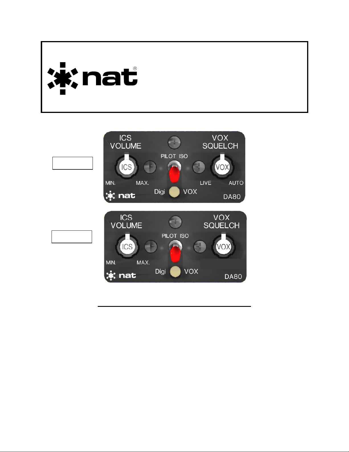
Front panel features include VOX SQUELCH and ICS VOLUME controls plus a toggle
switch for emergency operating (PILOT ISO) mode. Both modes have voice
annunciation. In the emergency mode (PILOT ISO) the pilot is separated from the copilot and passengers and the radio audio is removed from all other headsets.
When AutoVOX™ mode is selected, the squelch is automatically set by the processor
and depends on the ambient noise in the aircraft. The transmit keylines are monitored
for stuck mic condition and the processor will announce a message after 30 seconds of
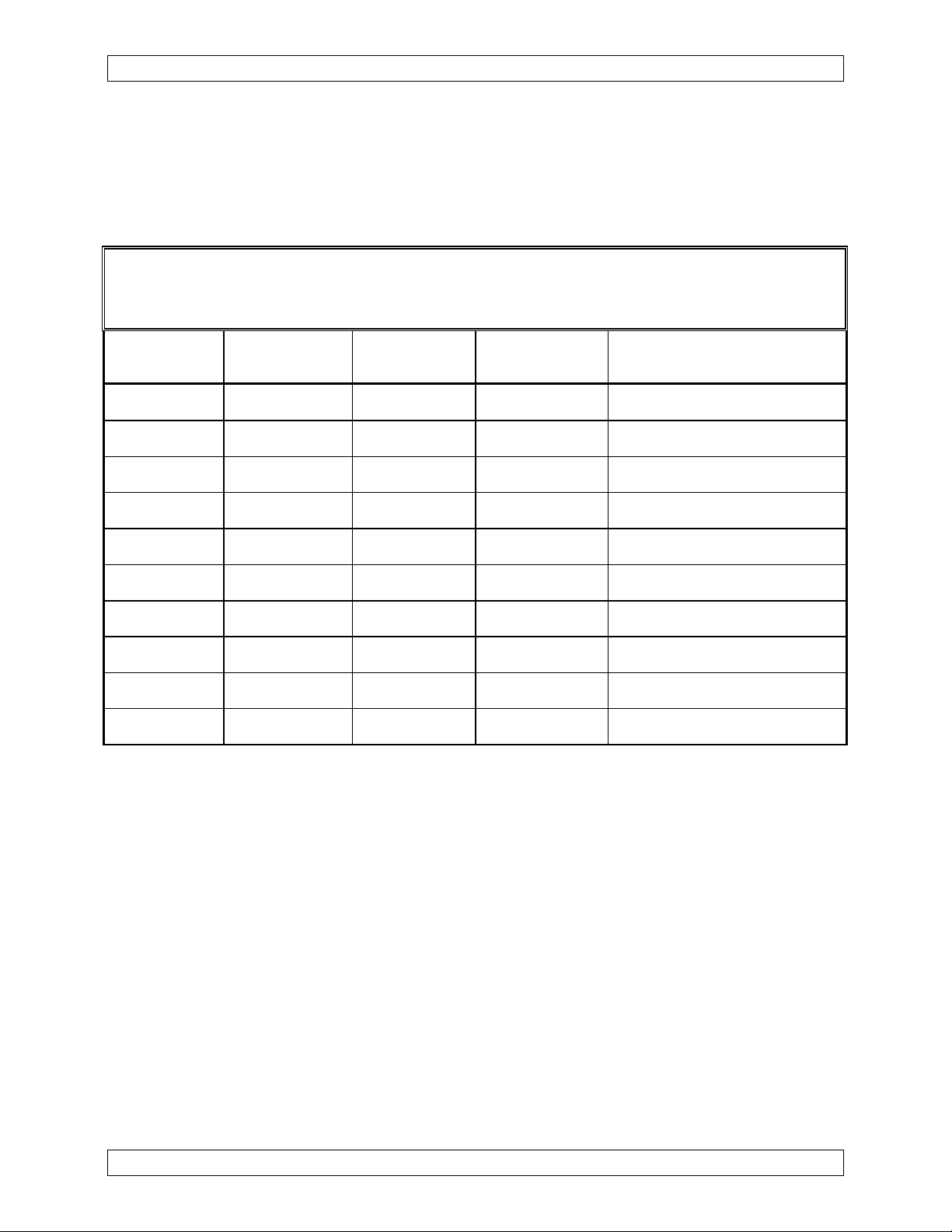
continuous transmission. For the DA80-001, this mode is selected when the VOX
SQUELCH knob is set to the fully clockwise position, and for the DA80-010, it is
selected when the VOX SQUELCH knob is set to the fully counterclockwise (ccw)
position.
Oct 13, 2004 Page 1-1
ENG-FORM: 800-0107.DOT
CONFIDENTIAL AND PROPRIETARY TO NORTHERN AIRBORNE TECHNOLOGY LTD.
Page 5

DA80 Series DigiVOX™ Digital Intercom Manual SM57 Rev. 4.10
A bi-color LED will show green for Transmit condition and amber for VOX operation.
High roll-off finite impulse response filters are used to shape the audio delivered to the
phones and radio microphone.
The following audio messages are embedded to provide information of system
operation.
DA80-001 DA80-010
• System Ready • System Ready
• Emergency Mode • Pilot Isolate
• Normal Mode • Normal Mode
• AutoVOX™ • AutoVOX™ Mode
• Stuck Mic. • Stuck Mic
1.4 Specifications
1.4.1 Electrical Specifications
Power Supply
Description: Multiple switches and linear regulators with
Normal operating conditions:
Nom. Operating Voltage: 27.5 Vdc / 13.8 Vdc
Max. Operating Voltage: 30.3 Vdc
Min. Operating Voltage: 11.0 Vdc
Input current 0.3 A max @ 27.5 Vdc
Input current 0.6 A max @ 13.8 Vdc
Input Signals
Quantity: 4 Microphone channels
1 Receive channel
2 Music channels (Left, Right)
2 Transmit key lines
1 Intercom key line (DA80-010 only)
Rated Level: 250 mVrms for microphone inputs
2.5 Vrms for receive input
500 mVrms for music inputs
reverse and over voltage protection. Short
circuit protected by internal fuse.
Page 1-2 Oct 13, 2004
ENG-FORM: 800-0107.DOT
CONFIDENTIAL AND PROPRIETARY TO NORTHERN AIRBORNE TECHNOLOGY LTD.
Page 6

SM57 Rev. 4.10 DA80 Series DigiVOX™ Digital Intercom Manual
DA80-001 only Transmit PTT<10 mA input current, active low
(3 Vdc max.)
DA80-010 only Transmit Key <15 mA input current, active low
(3 Vdc max)
ICS Key <15 mA input current, active low (3 Vdc
max)
Impedance: 1 kΩ ±10% for receive and music inputs
150 Ω ±10% for mic inputs
Circuitry Type: All inputs are single ended
Coupling: <-60dB input-to-input crosstalk
Output Signals
Quantity: 4 Phone outputs
1 Transmitter mic output
1 Transmitter keyline output
Rated Level:
Phones output: 100mW (7.7 Vrms) into 600 Ω
TX mic output: 250 mV rms nominal into 150 Ω
Circuitry Type: All outputs are single ended
Freq. Resp.:
Phones output:
Receive input <3 dB from 350 Hz to 6000 Hz
Music input <3 dB from 350 Hz to 6000 Hz
Intercom input <3 dB from 350 Hz to 6000 Hz
TX mic output <3 dB from 350 Hz to 6000 Hz
Distortion: <1% THD @ rated power output
Audio Noise Level: Without Signal: >70 dB down from rated output
Coupling: <-60 dB input-to-output crosstalk
Output regulation: <1% THD / 3dB max. of rated output power
At 400% and 75% of rated load
Oct 13, 2004 Page 1-3
ENG-FORM: 800-0107.DOT
CONFIDENTIAL AND PROPRIETARY TO NORTHERN AIRBORNE TECHNOLOGY LTD.
Page 7

DA80 Series DigiVOX™ Digital Intercom Manual SM57 Rev. 4.10
1.4.2 Physical Specifications
Dimensions: (Same size as the original AA80)
Height 1.35” (34.3 mm) max
Depth 5.62” (142.7 mm) max not including connector
Width 2.65” (67.3 mm) max
Weight 0.6 lb (0.272 kg) max
Faceplate Lexan label with vertical or horizontal legends.
Pressure sensitive adhesive backing attached
to a black anodized plate
Mounting Three black 6-32 brass screws that sandwich
the dash panel between the faceplate and
chassis. Aircraft panel thickness 0.050" to
0.125". The DA80 is mount-compatible with
the AA80-001
Material/Finish Brushed aluminum with chromate conversion
Connectors One 25 pin male (DB25P) D-min connector
with Jackposts
1.4.3 Environmental Specifications
Temperature:
Operating -20° C to +55° C
Survival -55° C to +85° C
Altitude 50,000 ft
Humidity 95%
Shock:
Operational 6 g
Crash Safety 15 g
Qualification:
DA80-001: DO-160C Env. Cat. A1/D1-XAB[(SBM)(UF)]XXXXXXZBABAXMXXXX
DA80-010: DO-160D Env. Cat. A1/D1-BAB[(SBM)(UF)]XXXXXXZBABA[UUX]LXXXX
Page 1-4 Oct 13, 2004
ENG-FORM: 800-0107.DOT
CONFIDENTIAL AND PROPRIETARY TO NORTHERN AIRBORNE TECHNOLOGY LTD.
Page 8

SM57 Rev. 4.10 DA80 Series DigiVOX™ Digital Intercom Manual
1.5 Unit Nomenclature
Model Description / Distinction
DA80-001 4 place operation.
Music muted during ICS and radio operations.
Individual mic gating.
Bi-color LED.
ICS volume and VOX Squelch controls.
Live, VOX and AutoVOX™ Intercom modes.
DA80-010 4 place operation.
Music muted during ICS and radio operations.
Individual mic gating.
Bi-color LED.
ICS volume and VOX Squelch controls.
PTT, VOX and AutoVOX™ Intercom modes.
End of section 1
Oct 13, 2004 Page 1-5
ENG-FORM: 800-0107.DOT
CONFIDENTIAL AND PROPRIETARY TO NORTHERN AIRBORNE TECHNOLOGY LTD.
Page 9

SM57 Rev. 4.10 DA80 Series DigiVOX™ Digital Intercom Manual
Section 2 Installation
2.1 Introduction
Information in this section consists of: unpacking and inspection procedures, installation
procedures, post-installation checks, and installation drawings.
Throughout this section the unit will be referred to as the DA80, and information
provided will be common to all models unless noted otherwise.
2.2 Unpacking and Inspection
Unpack the equipment carefully and locate the warranty card. Inspect the unit visually
for damage due to shipping and report all such claims immediately to the carrier
involved. Note that each unit should have the following:
- DA80 DigiVOX™ Digital Intercom
- Install Kit (with metal ‘hood’)
- Warranty Card
- Operators Manual
- Release certification
Verify that all items are present before proceeding and report any shortage immediately
to your supplier.
2.2.1 Warranty
Complete the warranty card information and send it to NAT when the installation is
complete. If you fail to complete the warranty card, the warranty will be activated on
date of shipment from NAT.
Note: An appropriately rated facility, e.g. Certified Aircraft Repair Station, must install
this equipment in accordance with applicable regulations. NAT Ltd’s warranty is
not valid unless the equipment is installed by an authorized NAT Dealer. Failure
to follow any of the installation instructions, or installation by a non-certified
individual or agency will void the warranty, and may result in a non-airworthy
installation.
Oct 13, 2004 Page 2-1
ENG-FORM: 805-0104.DOT
PROPRIETARY AND CONFIDENTIAL TO NORTHERN AIRBORNE TECHNOLOGY LTD.
Page 10

DA80 Series DigiVOX™ Digital Intercom Manual SM57 Rev. 4.10
2.3 Installation Procedures
2.3.1 Warnings
Do not bundle any lines from this unit with transmitter coax lines. Do not bundle any
audio or DC power lines from this unit with 400 Hz synchro wiring or AC power lines. Do
not position this unit or wiring from this unit next to any device with a strong alternating
magnetic field such as an inverter, or significant audio interference will result.
2.3.2 Cautions
In all installations, use shielded cable exactly as shown and ground as indicated.
Significant ground loop and noise problems may result from not following these guidelines.
Ensure that the chassis is grounded to provide proper shield terminations.
Ensure the microphone and headphone jacks are isolated from the airframe ground.
Use caution when routing microphone wiring, as it carries low-level signals prone to
coupling from other sources.
Do not take a ground from the instrument panel or similar location that shares a ground
return with a turn and bank, horizon or other motor driven instrument. This may cause
the unit to pick up the sound of the motor as ground loop interference.
2.3.3 Notes
The DA80 DigiVOX™ is designed to be used in place of the AA80-001 InterVOX™ unit.
If installing this unit into an existing aircraft harness, ensure that the harness connector
does not have the ‘tabs’ shown in figure 1. If the harness connector does have ‘tabs’,
replace the existing harness connector with the one included in the install kit.
Tab
Harness Connector
Figure 1
Page 2-2 Oct 13, 2004
ENG-FORM: 805-0104.DOT
PROPRIETARY AND CONFIDENTIAL TO NORTHERN AIRBORNE TECHNOLOGY LTD.
Page 11

SM57 Rev. 4.10 DA80 Series DigiVOX™ Digital Intercom Manual
2.3.4 Cabling and Wiring
All unshielded wire should be Tefzel MIL-M-22759 or equivalent. For shielded wire
applications, use Tefzel MIL-C-27500 shielded wire with solder sleeves (for shield
terminations) to make the most compact and easily terminated interconnect. Follow the
wiring diagrams in Section 2.6 as required.
Group the mic audio shields
separately from all other audio
shields.
Metal Hood
Utilizing Raychem solder sleeves,
create up to 6 shield pigtails in the
wiring harness, as shown in the
Interconnect Diagram
Raychem
Solder Sleeves
(DA80\xxx\403-0, Rev 1.00 or
higher, where xxx represents the
model of the unit under
consideration). Each pigtail
should be no more than 3.0" long.
Rubber
Grommet
Bring the pigtails through the
rubber grommet and strip off 0.5"
of insulation.
Bend the stripped portion back
onto the grommet as shown and
Stripped
Pigtail
sandwich the pigtails between the
connector hood and the grommet.
Note: The hood is a ‘two-piece’ unit, and is assembled after the wiring is complete.
All wiring should be at least 24 AWG, except power and ground lines, which should be
at least 20 AWG. Ensure that all ground connections are clean and well secured.
To prevent system failure or inadequate equipment protection, supply power from a
dedicated 2.0 A circuit breaker.
Oct 13, 2004 Page 2-3
ENG-FORM: 805-0104.DOT
PROPRIETARY AND CONFIDENTIAL TO NORTHERN AIRBORNE TECHNOLOGY LTD.
Page 12

DA80 Series DigiVOX™ Digital Intercom Manual SM57 Rev. 4.10
2.3.5 Installation Options
The DA80 DigiVOX™ is designed to be used in place of the AA80-001 InterVOX™ unit.
When using a portable cassette/CD player with the DA80, NAT recommends that the
phone output should be used for interface to increase tone control and volume. (The
‘line out’ output lacks volume and tone control.) Set the volume about half way.
CAUTION
Certain aircraft installations may use a car type, am/fm cassette or CD
player. If it is necessary to use the ‘speaker’ outputs from the stereo
unit, a floating ground adapter and input attenuation network (resistors)
may be required to provide the correct system interconnect and to
prevent damage to the music input(s) of the DA80.
2.3.6 Adjustments
The unit ships from the factory with all internal adjustments set to the normal test levels.
Once installed in the aircraft, it may be desirable to change some of these settings to
best suit the local operating environment. The internal adjustments are located along
the left side of the unit and are as follows:
CAUTION
Before performing the following adjustments ensure the aircraft radio’s
volume control is set to produce 2.5 Vrms ±10 % at the input to the
DA80, or the mute functions may not operate correctly.
2.3.6.1 RECEIVE LEVEL
The setting can be adjusted by potentiometer RECEIVE LEVEL. The setting cannot be
fully muted. The cw rotation of this control will increase Receive audio input level.
2.3.6.2 TX LEVEL
The setting can be adjusted by potentiometer TX LEVEL. The setting cannot be fully
muted. The cw rotation of this control will increase TX Mic output signal level.
2.3.6.3 MUSIC LEVEL
The setting can be adjusted by potentiometer MUSIC LEVEL. The setting cannot be
fully muted. The cw rotation of this control will increase music audio volume level.
Page 2-4 Oct 13, 2004
ENG-FORM: 805-0104.DOT
PROPRIETARY AND CONFIDENTIAL TO NORTHERN AIRBORNE TECHNOLOGY LTD.
Page 13

SM57 Rev. 4.10 DA80 Series DigiVOX™ Digital Intercom Manual
2.3.7 Mechanical Installation
The DA80 Digital Intercom can be installed in any attitude, using the DA80-IKC
Installation kit (refer to Section 2.5 for details).
For proper installation, refer to Mounting Diagram (DA80\xxx\920-0, where xxx
represents the model of the unit under consideration) and the following steps:
a) Before proceeding to install the DA80 into the aircraft, secure the black metal
faceplate to the DA80 with one mounting screw (countersink holes facing out).
b) Remove the desired label from the sheet provided and using minimum pressure
align the label on the black faceplate. When the alignment is correct remove the
faceplate from the unit.
c) Lay the faceplate on a flat surface and press label firmly in place ensuring there
are no air bubbles.
d) Referencing the drill template, drill required mounting holes in the aircraft panel
and insert the DA80 from behind the panel.
e) Attach the black metal faceplate (with label attached) from the front, with the
countersunk holes facing out. Secure with the mounting screws provided.
Note: Ensure that the aircraft panel is tightly ‘sandwiched’ between the DA80
and faceplate.
f) Rotate the shaft of the VOX potentiometer fully ccw. Align the white marker on
the knob (part of 40-21-VOX2) to the LIVE position on the faceplate label. Using
a 0.05" Allen key, tighten the knob onto the potentiometer shaft.
g) Using a 0.05" Allen key, loosely attach the knob (part of 40-21-ICS2) onto the
ICS VOL potentiometer shaft. Rotate the shaft of the ICS VOL potentiometer
fully ccw. Using the Allen key, loosen the knob on the potentiometer shaft and
align the white marker on the knob (part of 40-21-ICS2) to the MIN. position on
the faceplate label. Using the Allen key, tighten the knob onto the potentiometer
shaft.
Oct 13, 2004 Page 2-5
ENG-FORM: 805-0104.DOT
PROPRIETARY AND CONFIDENTIAL TO NORTHERN AIRBORNE TECHNOLOGY LTD.
Page 14

DA80 Series DigiVOX™ Digital Intercom Manual SM57 Rev. 4.10
2.3.8 Post-Installation Checks
2.3.8.1 Voltage/resistance checks
Do not attach the DA80 until the following conditions are met.
Check the following:
a) Check P101, pin <1> for +12 to 30 Vdc relative to ground.
b) Check P101, pin <14> for continuity to ground (less than 0.5 Ω).
c) For the DA80-010 only, check P101, pin <25> for continuity to ground (less than
0.5 Ω) when the ICS KEY is activated.
2.3.8.2 Power On checks
Install the DA80 and power up the aircraft’s systems. Verify normal operation of all
functions. Refer to Section 3 for specific operation details.
a) Begin with only the pilot's headset installed, no hand mic. Check for correct radio
operation (both receive and transmit) and ICS operation. Check yoke (or cyclic)
switch action.
b) If there is a music source in the system turn it on and verify that music is heard in
all modes except PLT ISO. Check for proper mute operation.
Note: Unusual buzzes, hums or other background audio are symptomatic of
multiple grounds, or noisy external systems such as blowers or pumps
sharing wiring with the audio system. Failure to key or correctly modulate
a transmitter is often the result of forgetting to connect all required
grounds to the radio or external audio system.
c) Plug in the copilot's headset. Check for correct radio and ICS operation. Check
pilot's transmit priority. Check yoke or cyclic switch functions, if applicable.
d) Plug in the hand mic, and test for correct operation in all modes. It must activate
the transmitter(s) in all cases.
e) Plug in any remaining headsets, and check for correct ICS operation.
Note: Incorrect jack wiring is a common fault for rear passenger stations, and
may cause a wide range of problems.
f) To verify proper operation, all functions and levels should be checked in-flight.
Upon satisfactory completion of all performance checks, make the required log
entries and complete the necessary Regulatory Agency paperwork before
releasing the aircraft for service.
Page 2-6 Oct 13, 2004
ENG-FORM: 805-0104.DOT
PROPRIETARY AND CONFIDENTIAL TO NORTHERN AIRBORNE TECHNOLOGY LTD.
Page 15

SM57 Rev. 4.10 DA80 Series DigiVOX™ Digital Intercom Manual
2.4 Continued Airworthiness
Maintenance of the DA80 DigiVOX™ Digital Intercom is ‘on condition’ only. Periodic
maintenance of this product is not required.
2.5 Accessories Required
An installation kit is required to complete the installation. The DA80-IKC (crimp) is
supplied with the unit, and consists of the following:
DA80-IKC (crimp)
Quantity Description NAT Part #
1 Hole Overlay Drill Template 43-10-085
1 Front Label (Lexan) 43-41-080
1 Rectangular Black Faceplate (Blank) 50-04-851
1 Fluted Knob set (ICS) 40-21-ICS2
1 Fluted Knob set (VOX) 40-21-VOX2
3 CSK Black 6-32 Mounting Screws 25-11-028
1 D-min 25 pin Socket housing 20-21-025
25 MS Crimp Socket 20-26-901
1 Hood, D-min, Metal 20-28-028
2.6 Installation Drawings
DRAWING REV. DESCRIPTION TYPE Serial #’s
DA80-001
DA80\001\403-0 1.00 Digital Intercom Interconnect 1001 and up
DA80\001\405-0 1.00 Digital Intercom Connector Map 1001 and up
DA80\001\905-0 1.00 Digital Intercom Faceplate 1001 and up
DA80\001\920-0 1.00 Digital Intercom Mounting 1001 and up
DA80\001\922-0 1.00 Digital Intercom Mech. Installation 1001 and up
DA80-010
DA80\010\403-0 1.00 Digital Intercom Interconnect 1001 and up
DA80\010\405-0 1.00 Digital Intercom Connector Map 1001 and up
DA80\010\920-0 1.00 Digital Intercom Mounting 1001 and up
DA80\010\922-0 1.00 Digital Intercom Mech. Installation 1001 and up
Section 2 ends after these Drawings
Oct 13, 2004 Page 2-7
ENG-FORM: 805-0104.DOT
PROPRIETARY AND CONFIDENTIAL TO NORTHERN AIRBORNE TECHNOLOGY LTD.
Page 16

Page 17

Page 18

Page 19

Page 20

Page 21

Page 22

Page 23

Page 24

ICS VOX
VOLUME
PILOT ISO
SQUELCH
MAX.MIN.
AUTO PTT
VOXDigi
DA80
Page 25

SM57 Rev. 4.10 DA80 DigiVOX™ Digital Intercom Manual
Section 3 Operation
3.1 Introduction
Information in this section consists of the functional and operational procedures for the
DA80 Series DigiVOX™ Digital Intercoms.
Throughout this section the unit will be referred to as the DA80, and information
provided will be common to all models unless noted otherwise.
3.2 General
The DA80 Digital Intercom provides full radio and intercom capabilities for the pilot and
copilot, plus intercom and radio receive functions for up to two passengers. Music is
available at all positions.
The crew and passengers share a common VOX control, and one volume control sets
the ICS volume in all four headsets.
The DA80 is compatible with the AA80-001 InterVOX™ unit.
3.3 Controls and Indicators
VOX
ICS VOLUME
Control
SQUELCH
Control
Mode Switch
Note: This illustration shows the DA80-001.
3.3.1 Mode switch
This red, two position toggle switch is used for selecting the intercom mode.
3.3.1.1 DigiVOX™
The DigiVOX™ position connects all headsets. All headsets will hear aircraft radio
audio and music.
TX/ICS Indicator
Oct 13, 2004 Page 3-1
ENG-FORM: 806-0104.DOT
CONFIDENTIAL AND PROPRIETARY TO NORTHERN AIRBORNE TECHNOLOGY LTD.
Page 26

DA80 Series DigiVOX™ Digital Intercom Manual SM57 Rev. 4.10
3.3.1.2 PILOT ISO
The PILOT ISO position isolates the pilot from all intercom and music functions. The
aircraft radio connects to the pilot’s mic and headset directly. The copilot and
passengers will not be able to hear the aircraft radio audio, but will retain intercom and
music functions.
CAUTION
In PILOT ISO, the copilot position cannot transmit mic audio
but can still key the radio.
3.3.2 ICS VOLUME Control
The ICS VOLUME control is a rotary switch that is used to control the intercom volume
for all headsets. With ICS VOLUME set fully ccw, intercom volume will be at a
minimum. As the operator rotates the control cw, intercom volume will increase.
CAUTION
The DA80 has no front panel radio volume control. Take
care when adjusting aircraft radios as low radio volume may
affect the DA80 mute functions.
3.3.3 VOX SQUELCH Control
The DA80 VOX SQUELCH control is a rotary control that is used to set the level of audio
required to activate the microphones.
3.3.3.1 DA80-001
The DA80-001 VOX SQUELCH control is marked LIVE in its fully ccw position, and
AUTO in its fully cw position.
When the VOX SQUELCH control is set fully ccw (LIVE), the microphones will be active
at all times (Hot Mic). Ground operations, where little background noise is present,
commonly use this setting.
As the operator rotates the control in a cw direction the amount of audio required to
activate the microphone(s) increases. Noisy conditions, where ‘pilot fatigue’ may result,
commonly use this setting.
In the fully cw position, the AutoVOX™ mode is activated. The ambient noise at the
microphone will 'automatically' set the VOX threshold.
Page 3-2 Oct 13, 2004
ENG-FORM: 806-0104.DOT
CONFIDENTIAL AND PROPRIETARY TO NORTHERN AIRBORNE TECHNOLOGY LTD.
Page 27

SM57 Rev. 4.10 DA80 DigiVOX™ Digital Intercom Manual
3.3.3.2 DA80-010
The DA80-010 VOX SQUELCH control is marked AUTO in its fully ccw position, and
PTT in its fully cw position.
When the VOX SQUELCH control is set fully cw (PTT), the microphones will be muted
except when the intercom PTT line is activated (grounded).
As the operator rotates the control in a cw direction the amount of audio required to
activate the microphone(s) increases. Noisy conditions, where ‘pilot fatigue’ may result,
commonly use this setting.
In the fully ccw position, the AutoVOX™ mode is activated. The ambient noise at the
microphone will 'automatically' set the VOX threshold.
3.3.4 TX/ICS Indicator
The TX/ICS indicator is a dual-color LED, which will illuminate green during radio
transmit operations and amber during ICS operations.
3.4 Mute Functions
3.4.1 ICS Mute Functions
Normal Mode Pilot ISO
PLT Tx Key Mute No Mute
COP Tx Key Mute No Mute
3.4.1.1 DigiVOX™ Mode
In DigiVOX™ mode, intercom audio will mute at all positions whenever the pilot or
copilot ‘Keys’ the radio.
3.4.1.2 PILOT ISO
In PILOT ISO mode, copilot and passenger intercom audio will not mute when the pilot
or copilot ‘Keys’ the radio. The pilot has no connection to any intercom or music
functions and therefore no muting is required.
Oct 13, 2004 Page 3-3
ENG-FORM: 806-0104.DOT
CONFIDENTIAL AND PROPRIETARY TO NORTHERN AIRBORNE TECHNOLOGY LTD.
Page 28

DA80 Series DigiVOX™ Digital Intercom Manual SM57 Rev. 4.10
3.4.2 Music Mute Functions
Normal Mode Pilot ISO
PLT Tx Key Mute No Mute
COP Tx Key Mute No Mute
Rx Detect Mute No Mute
PAX ICS Mute Mute
Pilot ICS Mute N/A
Copilot ICS Mute Mute
ICS Key
Mute Mute
(DA80-010 only)
3. 4.2.1 DigiVOX™ Mode
In DigiVOX™ mode, music audio will mute at all positions when any crew member
‘Keys’ the radio. Music will also mute whenever aircraft radio audio is present or if the
ICS is active.
3. 4.2.2 PILOT ISO
In PILOT ISO mode, copilot and passenger music audio will not mute when the pilot
‘Keys’ the radio or when aircraft radio audio is present. Copilot and passenger music
audio will not mute if the copilot ‘Keys’ the radio. Both copilot and passenger music
audio will mute during all ICS operations.
End of section 3
Page 3-4 Oct 13, 2004
ENG-FORM: 806-0104.DOT
CONFIDENTIAL AND PROPRIETARY TO NORTHERN AIRBORNE TECHNOLOGY LTD.
 Loading...