

Page 1
Installation and Operation Manual
CC450-0V2
Communications Controller
SM16
ISSUE 1.11
Northern Airborne Technology Ltd.
1925 Kirschner Road
Kelowna, BC, Canada.
V1Y 4N7
Telephone (250) 763-2232
Facsimile (250) 762-3374
Issued on the authority of Northern Airborne Technology Ltd.
Copyright 1994
Page 2

Page 3

CC450-0V2 Communications Controller
Installation and Operation Manual
Prepared By: Checked By: Approved By:
The status of this installation and operation manual is controlled by issue shown on the title page. The
status of each section is controlled by revision shown in the footer of each page. All revisions affecting
sections of this manual have been incorporated into the latest issue.
ISSUE/REVISION RECORD
Manual Issue
Number
1.10 N/A N/A Mar 25, 1994
Section
Revision Number
Revision Description Issue Date
1.11 Section 1 Rev:1.00
Section 2 Rev:1.00
Section 3 Rev:1.00
Manual reformatted and updated Feb 11, 2008
Installation and Operation Manual Page ii
ENG-FORM: 820-0113.DOT
CONFIDENTIAL AND PROPRIETARY TO NORTHERN AIRBORNE TECHNOLOGY LTD.
Page 4

CC450-0V2 Communications Controller
Installation and Operation Manual
Table of Contents
Installation and Operation
Section Title Page
1 Description
1.1 Introduction ............................................................................................1-1
1.1 Introduction ............................................................................................1-1
1.2 General Information ...............................................................................1-1
1.3 Design Features..................................................................................... 1-1
1.4 Specifications.........................................................................................1-2
1.4.1 Electrical Specifications...................................................................1-2
1.4.2 Physical Specifications .................................................................... 1-2
1.4.3 Environmental Specifications ..........................................................1-2
1.5 Unit Nomenclature .................................................................................1-2
1.5.1 Number of Radios (
1.5.2 Panel Lighting (
1.5.3 Installed Options (
1.5.4 Model Number (
1.5.5 Models Available .............................................................................1-3
2 Installation
2.1 Introduction ............................................................................................2-1
2.2 Unpacking and Inspection......................................................................2-1
2.2.1 Warranty ..........................................................................................2-1
2.3 Continued Airworthiness ........................................................................ 2-1
2.4 Installation Procedures ..........................................................................2-1
2.4.1 Warnings..........................................................................................2-1
2.4.2 Cautions...........................................................................................2-2
2.4.3 Cabling and Wiring ..........................................................................2-2
2.4.4 Post-Installation Checks .................................................................. 2-3
2.4.5 Mechanical Mounting.......................................................................2-4
2.5 Adjustments and Connections ...............................................................2-4
2.5.1 Squelch Logic Threshold Adjustments ............................................ 2-4
2.5.2 Squelch VOX level Adjustments...................................................... 2-5
2.6 Squelch VOX Circuitry and Jumper Settings .........................................2-6
2.6.1 Cover Removal................................................................................2-6
2.6.2 Squelch Disable Logic Polarity Jumpers.........................................2-6
2.6.3 Receive Audio VOX Squelch Circuit Jumpers.................................2-7
2.6.4 Jumper JP101 .................................................................................2-8
2.6.5 Final Checks....................................................................................2-8
2.7 Accessories Required But Not Supplied................................................2-8
2.8 Installation Drawings..............................................................................2-9
n)......................................................................1-3
p) ............................................................................ 1-3
i) .........................................................................1-3
x) ...........................................................................1-3
Installation and Operation Manual Page iii
ENG-FORM: 820-0113.DOT
CONFIDENTIAL AND PROPRIETARY TO NORTHERN AIRBORNE TECHNOLOGY LTD.
Page 5

CC450-0V2 Communications Controller
Installation and Operation Manual
Section Title Page
3 Operation
3.1 Introduction ............................................................................................3-1
3.2 General Information ...............................................................................3-1
3.3 Controls and Indicators .......................................................................... 3-1
3.3.1 Power Switch...................................................................................3-1
3.3.2 Transceiver Controls .......................................................................3-2
3.3.3 Mode Selection Switch ....................................................................3-2
3.4 Alert Tones............................................................................................. 3-3
3.5 Voice Store and Retransmit (VSR) [OPTIONAL]................................... 3-3
3.6 System Use............................................................................................ 3-4
Installation and Operation Manual Page iv
ENG-FORM: 820-0113.DOT
CONFIDENTIAL AND PROPRIETARY TO NORTHERN AIRBORNE TECHNOLOGY LTD.
Page 6

Page 7

CC450-0V2 Communications Controller
Installation and Operation Manual
Section 1 Description
1.1 Introduction
This manual contains information on the CC450-0V2 Communications Controllers. All derivative product
information shall be contained in the applicable manual supplement, which may be obtained from NAT as
required.
Information in this section consists of purpose of equipment, features and specifications. Review all
notes, warnings and cautions.
1.2 General Information
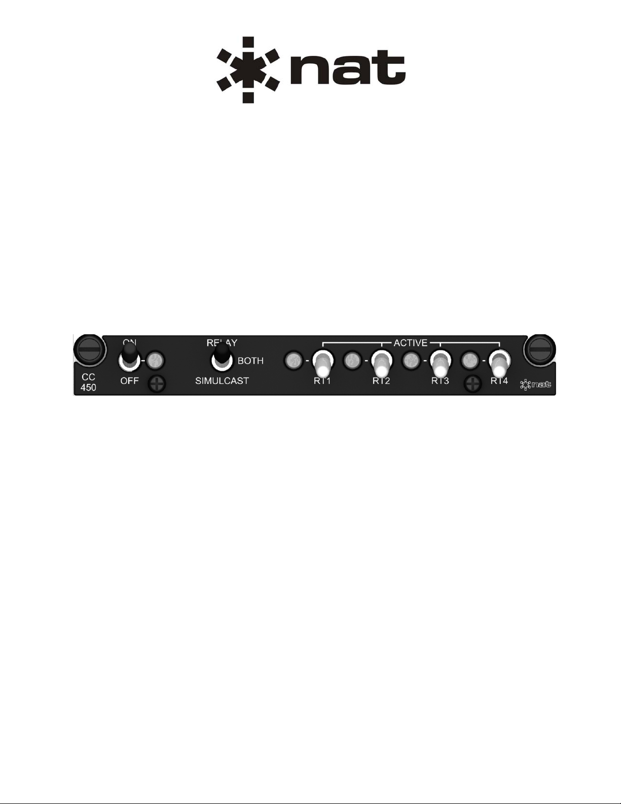
The CC450-0V2 is a compact, easy to install communications controller. It is designed to provide RELAY
and/or SIMULCAST operation for up to 4 transceivers. With these functions, the aircraft can become an
airborne repeater or a multi-frequency transmitting platform. When used to its potential, the CC450-0V2
provides increased efficiency and reduced workload for communication operations.
The CC450-0V2 Communications Controllers were designed to meet the requirement for expanded
operation of aircraft communications systems. Its modes of operation are: RELAY, SIMULCAST or
BOTH. All controllers are available with a Voice Store and Retransmit (VSR) option to increase single
radio capability.
RELAY operation is used when transmissions from one party must be re-transmitted from the aircraft to
reach groups on different frequencies or frequency bands, and when line-of-sight transmissions are not
possible.
SIMULCAST operation is used when a single transmission must reach groups operating on different
frequencies or frequency bands.
BOTH operation includes both RELAY and SIMULCAST functions, with priority given to the SIMULCAST mode.
Voice Store and Retransmit operation is used when two parties are unable to communicate directly due to
obstacles or distances that affect the transmission path. The transmission from one party is stored and
then retransmitted on the same channel to the other party.
1.3 Design Features
The CC450-0V2 requires only 0.75" of panel space and is available with +5 or +28Vdc panel lighting.
All audio inputs and outputs are transformer-coupled to provide full isolation from the existing audio
system. Bi-coloured annunciators on the front panel illuminate to indicate a RX or TX condition for each radio.
The Controller generates alert tones at the beginning and end of each transmission to indicate to the
operator that the CC450-0V2 is active.
In-band Voice Store and Retransmit option allows RELAY operation on one transceiver. This is
accomplished by storing RX audio (up to 16 seconds for the -xx1, or 60 seconds for the -xx2) in the
controller and then retransmitting the message out on the same radio.
Voice Activated Squelch Disable (squelch VOX) is provided for interfacing transceivers without a Squelch
Disable Output (only available on RT1 and RT2 for –xx1 models).
Section 1 Rev: 1.00 Issue 1 Page 1-1
ENG-FORM: 800-0112.DOT
CONFIDENTIAL AND PROPRIETARY TO NORTHERN AIRBORNE TECHNOLOGY LTD.
Page 8

CC450-0V2 Communications Controller
Installation and Operation Manual
1.4 Specifications
1.4.1 Electrical Specifications
Input power +28 Vdc
Supply Current 600 mAdc (Max)
Lights Current 80 mAdc (Max) @ +28 Vdc
400 mAdc (Max) @ +5 Vdc
Inputs (Each RT) MIC HI, MIC LO, PTT, RX AUDIO HI and LO,
SQUELCH DISABLE
Outputs (Each RT) MIC HI, MIC LO, PTT
Serial Ports One Serial Port (RS232)
Annunciators: Power On - Green
RT1 to RT4 Status - Green (TX) I Orange (RX)
1.4.2 Physical Specifications
Height 0.74" (18.8 mm)
Depth behind panel 6.24" (158.5 mm) excluding connectors
Width 5.75" (146.1 mm)
Weight 1.1Ib (500 g)
Connectors One Male 37-Pin Dmin
One Male 15-Pin Dmin
Dummy Plug (Included in install kit) One Male 37-Pin Dmin
Mounting Panel Mount using 2 Dzus Fasteners
1.4.3 Environmental Specifications
Operating Temperature -40°C to + 70°C
Storage Temperature -55°C to + 85°C
Altitude 25,000 feet
Humidity 95% Non-condensing
1.5 Unit Nomenclature
Variants of the CC450 series Communications Controller are identified as follows:
CCn50-pix
x = Other Options
n = Number of Radios
p = Panel Lighting
i = Installed Options
Page 1-2 Issue 1 Section 1 Rev: 1.00
ENG-FORM: 800-0112.DOT
CONFIDENTIAL AND PROPRIETARY TO NORTHERN AIRBORNE TECHNOLOGY LTD.
Page 9

CC450-0V2 Communications Controller
Installation and Operation Manual
1.5.1 Number of Radios (n)
The digit immediately after the CC identifier indicates the number of radios that can be controlled by the unit.
2 = Two-Transceiver Model (No longer in production)
4 = Four-Transceiver Model
1.5.2 Panel Lighting (
p)
The digit in the first position of the unit suffix indicates the panel lighting voltage.
0 = +28 Vdc Lights
5 = +5 Vdc Lights
7 = +28 Vdc NVG Compatible Lights
Note: NVG compatible lighting may be available. Contact NAT for more information.
1.5.3 Installed Options (
i)
The digit in the second position of the unit suffix indicates any installed options.
0 = No Options
V = With Voice Storage Option
1.5.4 Model Number (x)
The digit in the third position of the unit suffix indicates the model number.
1 = 16 seconds of RX Audio stored
2 = 60 seconds of RX Audio stored
1.5.5 Models Available
Some of the models currently available are as follows:
CC450-001 Four-transceiver model, 16 seconds Voice Storage, +28 Vdc panel lighting
CC450-0V1 Four-transceiver model, 16 seconds Voice Storage, +28 Vdc panel lighting
CC450-0V2 Standard Four-transceiver model, 60 seconds Voice Storage, +28 Vdc panel lighting
CC450-5V2N Four-transceiver model, 60 seconds Voice Storage, +5 Vdc NVG suitable panel lighting
CC450-7V2 Four-transceiver model, 60 seconds Voice Storage, +28 Vdc NVG compatible panel lighting
Section 1 ends
Section 1 Rev: 1.00 Issue 1 Page 1-3
ENG-FORM: 800-0112.DOT
CONFIDENTIAL AND PROPRIETARY TO NORTHERN AIRBORNE TECHNOLOGY LTD.
Page 10

CC450-0V2 Communications Controller
Installation and Operation Manual
This page intentionally left blank.
Page 1-4 Issue 1 Section 1 Rev: 1.00
ENG-FORM: 800-0112.DOT
CONFIDENTIAL AND PROPRIETARY TO NORTHERN AIRBORNE TECHNOLOGY LTD.
Page 11

CC450-0V2 Communications Controller
Installation and Operation Manual
Section 2 Installation
2.1 Introduction
Information in this section consists of unpacking and inspection procedures, installation procedures, postinstallation checks and installation drawings. Review all notes, warnings and cautions before installation.
2.2 Unpacking and Inspection
Unpack the equipment carefully and locate the warranty card. Inspect the unit visually for damage due to
shipping and report all such claims immediately to the carrier involved. Check that all items listed below
are present before proceeding and report any shortage immediately to your supplier:
- Warranty Card
- Operators Manual
- Certificate of Conformity or Release Certification
2.2.1 Warranty
Complete the warranty card information and send it to NAT Ltd. when installation is complete. If you fail
to complete the warranty card, the warranty will be activated on shipment date from NAT Ltd.
Note: An appropriately rated facility, e.g. Certified Aircraft Repair Station, shall install this
equipment in accordance with applicable regulations. NAT Ltd’s. warranty is not valid unless
an authorized NAT Ltd. Dealer installs the equipment. Failure to follow any of the installation
instructions, or installation by a non-certified individual or agency will void the warranty, and
may result in a non-airworthy installation.
2.3 Continued Airworthiness
Maintenance of the CC450-0V2 Communications Controller is ‘on condition’ only. Periodic maintenance
of this product is not required.
2.4 Installation Procedures
2.4.1 Warnings
WARNING:
High volume settings can cause hearing damage.
Set the headset volume control to the minimum volume setting prior to
conducting audio tests, and slowly increase the headset volume to a
comfortable listening level.
Section 2 Rev: 1.00 Issue 1 Page 2-1
ENG-FORM: 805-0114.DOT
CONFIDENTIAL AND PROPRIETARY TO NORTHERN AIRBORNE TECHNOLOGY LTD.
Page 12
2.4.2 Cautions
Do not bundle any lines from this unit with transmitter coax lines. Do not
bundle any logic, audio, or DC power lines from this unit with 400 Hz synchro
wiring or AC power lines. Do not position this unit next to any device with a
strong alternating magnetic field, such as an inverter, or significant
audio interference will result. In all installations, use shielded cable exactly
as shown and ground as indicated. Significant problems may result from not
following these guidelines.
Microphone signals run through the CC450-0V2 unit. If the controller is
removed, a Dummy Plug (included with the Installation kit) must be installed
on the harness plug P101. Failure to install the Dummy Plug will prevent
transmitting from all transceivers connected to the CC450.
Ensure proper antenna ground plane and sufficient antenna spacing between
transceivers that will be used in RELAY operation. If enough power is
transmitted from an adjacent antenna to the receiving transceiver's antenna, the
receiver may stop functioning. Spurious receiver responses from transceivers
with weak front ends, such as handheld units, will also be minimized with proper
ground plane and antenna spacing.
CC450-0V2 Communications Controller
Installation and Operation Manual
CAUTION:
CAUTION:
CAUTION:
2.4.3 Cabling and Wiring
All wire shall be selected in accordance with the original aircraft manufacturer's Maintenance Instructions
or AC43.13-1B Change 1, Paragraphs 11-76 through 11-78. Unshielded wire types shall qualify to
MIL-W-22759 as specified in AC43.13-1B Change 1, Paragraphs 11-85, 11-86, and listed in Table 11-11.
For shielded wire applications, use Tefzel MIL-C-27500 shielded wire with solder sleeves (for shield
terminations) to make the most compact and easily terminated interconnect. Follow the connector map in
Section 2.7 as required.
Coaxial cable shall be selected in accordance with MIL-C-17 unless otherwise specified. Do not use coax
cable with PVC insulation. Teflon dielectric cable is encouraged at or above VHF frequencies or where
cable runs exceed 8 feet. Note that at VHF frequencies, cables losses due to long cable runs and tight
bends may reduce the ERP (Equivalent Radiated Power) by greater than 50%.
Allow 3" from the end of the shielded wiring to the shield termination to allow the connector hood to be
easily installed. Reference the interconnect drawing in Section 2.7 for shield termination details. Note
that the hood is a "clamshell" hood, and is installed after the wiring is complete. Aircraft harnessing shall
permit the unit to be lowered from the panel for easy access to all side adjustments. Do NOT mount the
unit until all adjustments have been performed.
Maintain wire segregation and route wiring in accordance with the original aircraft manufacturers
Maintenance Instructions. Coaxial cables shall be routed separately from existing wire bundles in the
aircraft to minimize electromagnetic coupling effects.
Unless otherwise noted, all wiring shall be a minimum of 22 AWG, except power and ground lines, which
shall be a minimum of 20 AWG. Check that the ground connection is clean and well secured, and that it
Page 2-2 Issue 1 Section 2 Rev: 1.00
ENG-FORM: 805-0114.DOT
CONFIDENTIAL AND PROPRIETARY TO NORTHERN AIRBORNE TECHNOLOGY LTD.
Page 13

CC450-0V2 Communications Controller
Installation and Operation Manual
shares no path with any electrically noisy aircraft accessories such as blowers, turn and bank instruments
or similar loads. Power to this unit must be supplied from a separate circuit breaker or fuse (fast blow),
and not attached to any other circuit breaker without additional protection. Verify that the selected circuit
breaker size and wire gauge are adequate for the installation using the techniques specified in
AC41.13-1B Change 1, Paragraphs 11-47 through 11-51 and 11-66 through 11-69.
Microphone signals run through the CC450-0V2 unit. If the controller is removed, a Dummy Plug
(included with the Installation kit) must be installed on the harness plug P101. Failure to install the
Dummy Plug will prevent transmitting from all transceivers connected to the CC450.
Ensure proper antenna ground plane and sufficient antenna spacing between transceivers that will be used
in RELAY operation. If enough power is transmitted from an adjacent antenna to the receiving transceiver's
antenna, the receiver may stop functioning. Spurious receiver responses from transceivers with weak front
ends, such as handheld units, will also be minimized with proper ground plane and antenna spacing.
2.4.4 Post-Installation Checks
2.4.4.1 Voltage/Resistance Checks
Do not attach the CC450-0V2 until the following conditions are met.
Check the following:
a) P101 pin <18> for appropriate lights voltage.
b) P101 pin <19> for +28 Vdc relative to ground.
b) P101 pins <4>, <8>, <12>, <23>, <27>, and <31> for shield ground (below 0.5 Ω).
c) P101 pins <35>, <36> and <37> for continuity to ground (less than 0.5 Ω).
d) P102 pin <14> for chassis ground (less than 0.5 Ω).
2.4.4.2 Power On Checks
Power up the aircraft’s systems and confirm normal operation of all functions of the CC450. Refer to
Section 3 (Operation) for specific operational details.
WARNING:
High volume settings can cause hearing damage.
Set the headset volume control to the minimum volume setting prior to
conducting audio tests and slowly increase the headset volume to a
comfortable listening level.
Upon satisfactory completion of all performance checks, make all required log book entries, electrical
load, weight and balance amendments and other documentation as required by your local regulatory
agency before releasing the aircraft for service.
Section 2 Rev: 1.00 Issue 1 Page 2-3
ENG-FORM: 805-0114.DOT
CONFIDENTIAL AND PROPRIETARY TO NORTHERN AIRBORNE TECHNOLOGY LTD.
Page 14
CC450-0V2 Communications Controller
Installation and Operation Manual
2.4.5 Mechanical Mounting
The CC450-0V2 requires a standard Dzus rail assembly with an opening width of 5.0” and a front
clearance width of 5.75”. The height requirement is 0.75”. Be sure that adequate clearance is allowed for
the cable connections at the rear of the unit.
Note: Ensure that proper mechanical support is provided under the chassis. Due to the shallow profile of
the unit, the Dzus fasteners should not be relied upon for complete mechanical support. NAT Ltd
recommends that it should be mounted above another unit, such as a control head, to provide
better mechanical support.
2.5 Adjustments and Connections
CAUTION
Incorrect setting of these adjustments may cause improper operation of
the CC450-0V2 during relay operations.
These adjustments have been factory set to operate correctly with NAT NT-Series, NTX-Series, NPXSeries and NCT-Series, Wulfsberg Flexcomm, and Wulfsberg RT9600/7200 transceivers. For any
other manufacturer's radios, consult NAT Ltd.
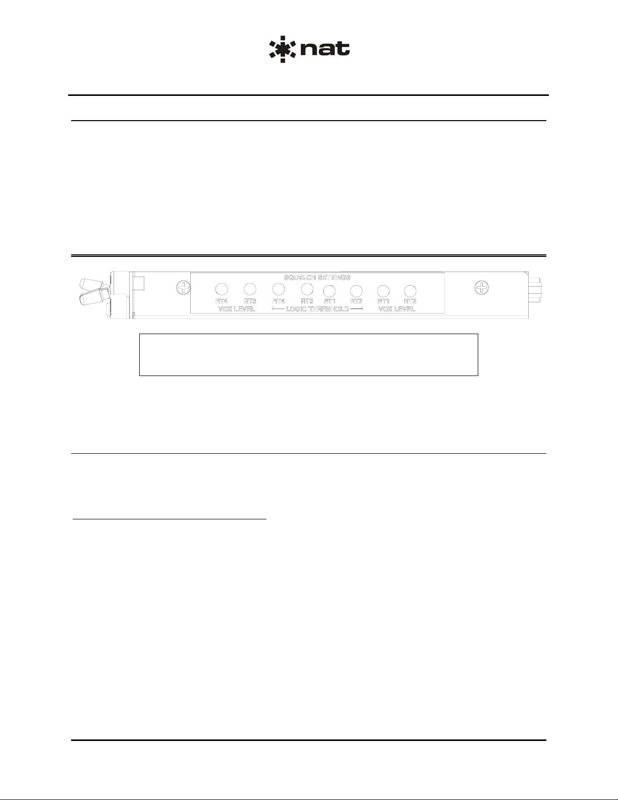
2.5.1 Squelch Logic Threshold Adjustments
The Squelch Logic Threshold settings control the voltage at which the CC450-0V2 recognizes that the
Squelch Disable line has gone active (the transceiver is receiving). It is normally set to 1.0 Vdc Active Lo
or grounded signal.
2.5.1.1 'Active Lo' Squelch Disable
a) Put all the CC450-0V2 Transceiver Select switches in the down (inactive) position.
b) Power up the CC450-0V2 by putting the Power switch in the up (ON) position
c) Turn the Squelch Logic Threshold Adjustment fully counterclockwise (ccw).
d) Slowly turn the adjustment clockwise (cw) until the stops are reached or the RX/TX annunciator on
the CC450-0V2 lights ORANGE.
e) Take note of the adjustment position
f) While depressing the Squelch Test button for the respective transceiver, rotate the adjustment ccw until
the stops are reached or the RX/TX annunciator goes out.
g) Take note of the adjustment position
h) Release the Squelch Test button.
i) Position the adjustment half way between the positions reached in steps e) and g).
Page 2-4 Issue 1 Section 2 Rev: 1.00
ENG-FORM: 805-0114.DOT
CONFIDENTIAL AND PROPRIETARY TO NORTHERN AIRBORNE TECHNOLOGY LTD.
Page 15

CC450-0V2 Communications Controller
Installation and Operation Manual
j) Ensure proper Squelch Disable operation by pushing the squelch test button for the transceiver. The
RX/TX annunciator on the CC450-0V2 should light ORANGE.
k) Repeat the above procedure for all active low disable transceivers connected to the CC450.
2.5.1.2 'Active Hi' Squelch Disable Signal (Wulfsberg FF40)
a) Put all the CC450-0V2 Transceiver Select switches in the down (inactive) position.
b) Power up the CC450-0V2 by putting the Power switch in the up (ON) position.
c) Turn the Squelch Logic Threshold Adjustment fully cw.
d) Slowly turn the adjustment ccw until the stops are reached or the RX/TX annunciator on the CC450-
0V2 lights ORANGE.
e) Take note of the adjustment position
f) While depressing the Squelch Test button for the respective transceiver, rotate the adjustment cw until
the stops are reached or the RX/TX annunciator goes out.
g) Take note of the adjustment position.
h) Release the squelch test button.
i) Position the adjustment half way between the two positions reached in steps e) and g).
j) Ensure proper Squelch Disable operation by pushing the squelch test button for the transceiver. The
RX/TX annunciator on the CC450-0V2 should light ORANGE.
k) Repeat the above procedure for all active high disable transceivers connected to the CC450.
2.5.2 Squelch VOX level Adjustments
The Squelch VOX circuitry must be enabled for use with transceivers that do not have a squelch disable
signal (such as a handheld or portable). See Section 2.5 for further details on enabling the Squelch VOX
circuitry.
The Squelch VOX adjustment is used to set the audio level required for the CC450-0V2 to recognize that
the transceiver is receiving. Normally this adjustment is set to the fully cw position, and the Squelch VOX is
disabled internally. The adjustment is rotated ccw to make the Squelch VOX trip on smaller signals, and cw
to trip on larger audio signals. (This feature is only available for the RT1 and RT2 positions of the -xV1
models.)
If the Squelch VOX is enabled internally, then setting the Squelch VOX Level (SVL) can be performed by
the following procedure:
a) Connect a communications monitor, or use another radio to transmit audio to the transceiver that is
connected to the VOX circuit of the CC450.
b) Put all the CC450-0V2 Transceiver Select switches in the down (inactive) position.
c) Power up the CC450-0V2 by putting the Power switch in the up (ON) position
d) Transmit to the CC450-0V2 RT, and adjust the receive audio volume to a comfortable level that would
be used during flight.
e) Adjust the setting of the SVL pot so that when there is an audio signal on the receive audio line, the
TX/RX annunciator on the CC450-0V2 will light ORANGE. When there is no audio being received the
TX/RX annunciator should not be lit.
Section 2 Rev: 1.00 Issue 1 Page 2-5
ENG-FORM: 805-0114.DOT
CONFIDENTIAL AND PROPRIETARY TO NORTHERN AIRBORNE TECHNOLOGY LTD.
Page 16

CC450-0V2 Communications Controller
Installation and Operation Manual
2.6 Squelch VOX Circuitry and Jumper Settings
CAUTION:
The Squelch VOX circuitry adjustments are only accessible by removing the top
cover of the unit. As this unit contains electrostatic discharge sensitive
components, this should only be undertaken by a certified technician at a static
protected workstation.
2.6.1 Cover Removal
Refer to Exploded View CC450\904-1 for enclosure removal.
a) Remove the four jackposts from the back of the unit using a 3/16" driver or socket.
b) Remove the two Phillips countersunk screws from each side of the unit.
c) Carefully slide the cover back (to clear the connectors) and upwards. It may be difficult to grip the
cover and gentle prying from behind the front plate may be required.
2.6.2 Squelch Disable Logic Polarity Jumpers
These jumpers determine if the Squelch Disable line will be active low (grounded = on) or active high
(voltage = on) logic polarity. Normally this jumper is set to the active low position for all transceivers. The
only exception is the Wulfsberg FF40 series transceivers, which use the active high position.
2.6.2.1 Main Board
The diagram below shows the applicable section of the main board.
Jumper JP104 (RT2)
Position Squelch Disable Logic Polarity
1-2, 3-4 Active Low (Normal Position)
1-3, 2-4 Active High
Jumper JP102 (RT1)
Position Squelch Disable Logic Polarity
1-2, 3-4 Active Low (Normal Position)
1-3, 2-4 Active High
Page 2-6 Issue 1 Section 2 Rev: 1.00
ENG-FORM: 805-0114.DOT
CONFIDENTIAL AND PROPRIETARY TO NORTHERN AIRBORNE TECHNOLOGY LTD.
Page 17

CC450-0V2 Communications Controller
Installation and Operation Manual
2.6.2.2 Auxiliary Board
The diagram below shows the applicable section of the auxiliary board.
Jumper JP201 (RT3)
Position Squelch Disable Logic Polarity
1-3, 2-4 Active Low (Normal Position)
1-2, 3-4 Active High
Jumper JP202 (RT4)
Position Squelch Disable Logic Polarity
1-3, 2-4 Active Low (Normal Position)
1-2, 3-4 Active High
2.6.3 Receive Audio VOX Squelch Circuit Jumpers
CC450-xV2
These jumpers enable or disable the Receive Audio VOX Squelch circuitry for the RT1, RT2, RT3 and
RT4 channels. Refer to Section 5.6.2 of this manual if any of these jumpers are enabled.
Jumper JP105 (RT2)
Position Receive Audio VOX Circuit
1-2 Disabled (Normal Position)
2-3 Enabled
Jumper JP103 (RT1)
Position Receive Audio VOX Circuit
1-2 Disabled (Normal Position)
2-3 Enabled
Jumper JP204 (RT4)
Position Squelch VOX Circuit
1-2 Disabled (Normal Position)
2-3 Enabled
Jumper JP203 (RT3)
Position Squelch VOX Circuit
1-2 Disabled (Normal Position)
2-3 Enabled
Section 2 Rev: 1.00 Issue 1 Page 2-7
ENG-FORM: 805-0114.DOT
CONFIDENTIAL AND PROPRIETARY TO NORTHERN AIRBORNE TECHNOLOGY LTD.
Page 18

CC450-0V2 Communications Controller
Installation and Operation Manual
2.6.4 Jumper JP101
For correct operation, this jumper must be in the
1-2 position. This diagram is included to ensure
that the installer can replace the jumper if it is
accidentally dislodged.
Jumper JP101
Position
1-2 Normal Position
2.6.5 Final Checks
If any preset requires adjustment, be sure this is carried out before the aircraft leaves, and that the unit
and its mating connector are secured before departure. Make all required log book entries, electrical
load, weight and balance amendments and other paperwork as required by your local regulatory agency.
2.7 Accessories Required But Not Supplied
The CC450-IKC kit consists of one D15SL-IKC, one D37SL-IKC, and one CC450-DMY. The contents of
each of these kits are listed below.
NAT Part #: D15SL-IKC consists of:
Quantity Description NAT Part #
1 D-min 15 Socket Housing 20-21-015
15 MS Crimp Socket 20-26-901
1* Jack Screw Set 20-27-002
1* Lock Clip Set 20-27-004
1 15 Pin Connector Hood 20-29-015
NAT Part #: D37SL-IKC consists of:
Quantity Description NAT Part #
1 D-min 37 Socket Housing 20-21-037
37 MS Crimp Socket 20-26-901
1* Jack Screw Set 20-27-002
1* Lock Clip Set 20-27-004
1 37 Pin Connector Hood 20-29-038
NAT Part #: CC450-DMY is a fully assembled Dummy Load that allows operation to continue if the
CC450-0V2 is removed for service. It consists of:
Quantity Description NAT Part #
1 D-sub plug, Solder cup 20-10-037
1 Hood, D-sub, plastic 20-29-038
1* Jack Screw Set 20-27-002
* Use as required.
Page 2-8 Issue 1 Section 2 Rev: 1.00
ENG-FORM: 805-0114.DOT
CONFIDENTIAL AND PROPRIETARY TO NORTHERN AIRBORNE TECHNOLOGY LTD.
Page 19

CC450-0V2 Communications Controller
Installation and Operation Manual
2.8 Installation Drawings
DRAWING REV. DESCRIPTION TYPE
CC450\403-0 1.20 Communications Controller Interconnect
CC450\403-1 - CC250/450 to NT Series RT and to Control Head Interconnect
CC450\403-2 1.01 Communication Controller Interconnect
CC450\403-3 - CC250/450 to Wulfsberg RT7200/9600 Interconnect
CC450\403-4 - CC250/450 to Wulfsberg Flexcomm RT Interconnect
CC450\405-0 - CC250/450 Connector Maps Connector Map
CC450\405-1 - CC250/450 Dummy Plug Connector Map Connector Map
CC450\905-0 1.20 Communications Controller
(Sheet 1 of 3) Faceplate
CC450\0V2\922-0 1.10 Communications Controller Mech. Installation
Section 2 ends following the above documents
Section 2 Rev: 1.00 Issue 1 Page 2-9
ENG-FORM: 805-0114.DOT
CONFIDENTIAL AND PROPRIETARY TO NORTHERN AIRBORNE TECHNOLOGY LTD.
Page 20

CC450-0V2 Communications Controller
Installation and Operation Manual
This page intentionally left blank.
Page 2-10 Issue 1 Section 2 Rev: 1.00
ENG-FORM: 805-0114.DOT
CONFIDENTIAL AND PROPRIETARY TO NORTHERN AIRBORNE TECHNOLOGY LTD.
Page 21

Page 22

Page 23

Confidential and Proprietary to NAT
Page 24

Page 25

Confidential and Proprietary to NAT
Page 26

Page 27

Confidential and Proprietary to NAT
Page 28

Page 29

Confidential and Proprietary to NAT
Page 30

Page 31

Confidential and Proprietary to NAT
Page 32

Page 33

Confidential and Proprietary to NAT
Page 34

Page 35

CC
CC
450
450
BOTH
BOTH
ACTIVEACTIVE
RT1 RT2 RT3
RT3RT2RT1
Page 36

Page 37

Page 38

Page 39

CC
CC
450
450
BOTH
BOTH
ACTIVEACTIVE
RT1 RT2 RT3
RT3RT2RT1
Page 40

Page 41

CC
450
ACTIVE
BOTH
RT3RT2RT1
Page 42

Page 43

CC450-0V2 Communications Controller
Installation and Operation Manual
Section 3 Operation
3.1 Introduction
Information in this section consists of the functional and operational procedures for the CC450-0V2
Communications Controller. All derivative units operate in a similar manner, but may have minor
differences such as no transceiver annunciators.
3.2 General Information
The CC450-0V2 Communications Controller is a compact, easy to install communications controller. It is
designed to provide RELAY and/or SIMULCAST operation for up to 4 transceivers. With these functions, the
aircraft can become an airborne repeater or a multi-frequency transmitting platform.
When used to its potential, the CC450-0V2 provides increased efficiency and reduced workload for
communication operations.
3.3 Controls and Indicators
Once the function of each switch is understood, the CC450-0V2 Communications Controllers are very
simple to operate.
A description of the specific switch function and operation is listed below.
Power
Switch
Mode Selection
Switch
Transceiver Switches
Power
Annunciator
3.3.1 Power Switch
Before powering up the CC450-0V2 put all transceiver switches in the down (inactive) position.
To turn the unit on, move the Power Switch to the up (ON) position. The Power Annunciator should light
GREEN and the RT1 and RT2 Transceiver Annunciators should flash alternately for 0.5 seconds.
When the Power Switch is turned OFF, the CC450-0V2 will allow normal transmit and receive operation
of all transceivers that are connected to the CC450-0V2.
Transceiver Annunciators
Section 3 Rev: 1.00 Issue 1 Page 3-1
ENG-FORM: 806-0110.DOT
CONFIDENTIAL AND PROPRIETARY TO NORTHERN AIRBORNE TECHNOLOGY LTD.
Page 44

CC450-0V2 Communications Controller
Installation and Operation Manual
3.3.2 Transceiver Controls
3.3.2.1 Transceiver Switches
A transceiver is selected for control at the CC450-0V2 by putting the respective Transceiver Switch in the
up (ACTIVE) position.
Do not select transceivers that are turned OFF and do not select positions that do not have transceivers
connected. Improper operation of all modes will occur if these transceivers are selected.
3.3.2.1 Transceiver Annunciators
Each transceiver has one annunciator to indicate the status of the transceiver. When the CC450-0V2 is
ON, and the transceiver is transmitting, the annunciator will light GREEN. When the transceiver is
receiving a signal, the annunciator will light ORANGE. If the transceiver is turned off, the annunciator
may light orange, as the Squelch Disable line from the transceiver will float to an unknown level. The
CC450-0V2 will recognize this level as an active Squelch Disable signal.
3.3.3 Mode Selection Switch
There are three operating modes for the CC450-0V2, selected by the Mode Selection switch.
3.3.3.1 RELAY Mode
With the Mode switch in the 'up' position, the CC450-0V2 is in the RELAY mode. In this mode, the
received audio signal from any selected transceiver is transmitted out on the other selected
transceiver(s). Transmission of microphone audio is as selected by the Audio Controller.
If the microphone is keyed (PTT button pressed) for a transceiver that is transmitting a relayed audio
signal, then that transceiver is taken out of the relay for the duration of the microphone key. If the
microphone is keyed (PTT button pressed) for a transceiver that is receiving an audio signal to be
relayed, then the relay is stopped.
3.3.3.2 SIMULCAST Mode
With the Mode switch in the DOWN position, the CC450-0V2 is in the SIMULCAST mode.
In SIMULCAST mode, receive audio signals are not transmitted. Microphone audio is transmitted out on
the transceiver as selected by the Audio Controller. If the switch on the CC450-0V2 is used to select that
transceiver, then the microphone audio is transmitted on all transceivers selected at the CC450-0V2.
Page 3-2 Issue 1 Section 3 Rev: 1.00
ENG-FORM: 806-0110.DOT
CONFIDENTIAL AND PROPRIETARY TO NORTHERN AIRBORNE TECHNOLOGY LTD.
Page 45

CC450-0V2 Communications Controller
3.3.3.3 BOTH Mode
Installation and Operation Manual
With the Mode switch in the centre position the CC450-0V2 is in the BOTH mode
In BOTH mode, RELAY and SIMULCAST modes are combined, with priority given to SIMULCAST mode.
The received audio signal from any selected transceiver is transmitted (relayed) out on the other selected
transceiver(s).
Microphone audio is transmitted out on the transceiver as selected by the Audio Controller. If that
transceiver is selected by the transceiver switches on the CC450-0V2, then the microphone audio is
transmitted (simulcast) on all selected transceivers.
If a microphone is keyed on a selected transceiver and a relay is in progress, the relay is cancelled and
the microphone audio is transmitted (simulcast) on all selected transceivers.
3.4 Alert Tones
Alert Tones are generated to indicate that the CC450-0V2 is Relaying or Simulcasting signals. During
Simulcast, an alert tone is generated at the beginning of the transmission to notify the operator that his
signal will be simulcast. During Relay, an alert tone is produced at the beginning of the transmission to
notify receiver operators that they are receiving a relayed transmission. When the relay is over, an alert
tone is transmitted out on all selected transceivers to notify the receiver operators of the end of the
relayed transmission and the transmitter operator that the transmission was relayed.
3.5 Voice Store and Retransmit (VSR) [OPTIONAL]
The CC450-0V2 has the ability to store up to 60 seconds of receive audio signal from a transceiver and
Retransmit that signal on the same transceiver.
To set up the CC450-0V2 for VSR operation, the mode switch must be in the RELAY position and only
one transceiver selected as active.
Up to 60 seconds of receive audio signal from the selected transceiver will be stored. If the receive audio
signal is longer than 60 seconds, then only the first 60 seconds will be stored. When the receive activity
is ended, the CC450-0V2 will transmit the stored signal out on the transceiver selected as active.
Note: In earlier versions (CC450-xV1 models) this storage time was 16 seconds.
Section 3 Rev: 1.00 Issue 1 Page 3-3
ENG-FORM: 806-0110.DOT
CONFIDENTIAL AND PROPRIETARY TO NORTHERN AIRBORNE TECHNOLOGY LTD.
Page 46

CC450-0V2 Communications Controller
Installation and Operation Manual
3.6 System Use
The CC450-0V2 has the ability to greatly increase the communications capability during multi-agency
operations. However, care must be exercised with the use of the CC450-0V2 system to keep
communications efficient. Ground based users and other parties that will be transmitting to, or receiving
from the CC450-0V2, must be knowledgeable about the operating parameters of the system to avoid
confusion or misunderstood communications.
Parties using the CC450-0V2 must understand that an alert tone will precede and follow each
transmission. The alert tone signifies that the transmission being received is being processed through the
CC450-0V2.
Operators of the CC450-0V2 should be aware that a small amount of time is required between pressing
the PTT switch on the microphone, and the selected transceivers being able to transmit. During
Simulcast, the CC450-0V2 delays up to one fifth of a second after it detects a PTT, then generates the
alert tone. The user will hear the alert tone through the sidetone, after which speech may be transmitted.
During RELAY operation, a ground user should wait at least one second from pressing the PTT switch
before speaking into the microphone. This one-second delay is required because of the extra
transceivers and the CC450-0V2 in the transmission path. If the user speaks into the microphone
immediately upon depressing the PTT button, the first few syllables may be omitted from the
transmission.
Section 3 ends
Page 3-4 Issue 1 Section 3 Rev: 1.00
ENG-FORM: 806-0110.DOT
CONFIDENTIAL AND PROPRIETARY TO NORTHERN AIRBORNE TECHNOLOGY LTD.
 Loading...