

Page 1
Installation and Operation Manual
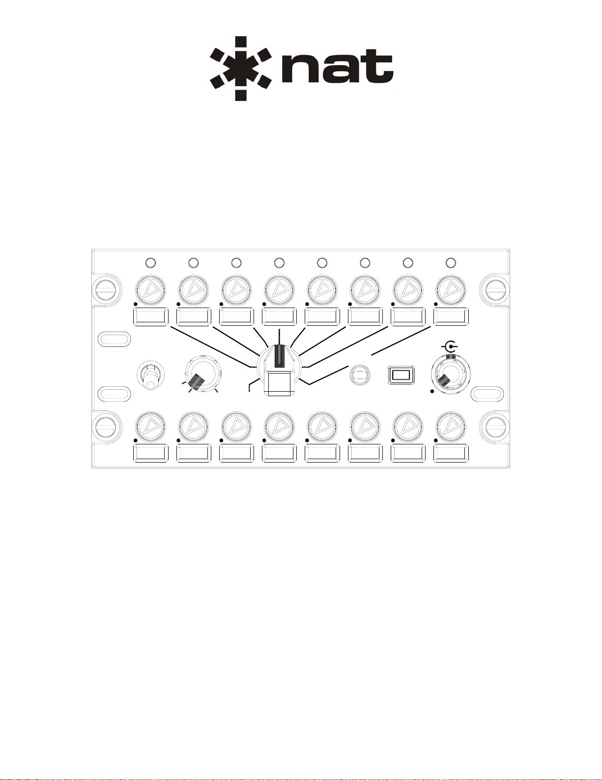
ACP53-001
DACS Audio Control Panel
TX
VOX
EMER
EMER
BK-UP
BK-UP
ISO CALL
NORM
NORM
VOX
MIN
MIN
PRESET
PRESET
PTT
PTT
ICS
ICS
ICS
ICS
TX
TX
ISO
ISO
CALL
CALL
ICSRX
ICSRX
SM75
ISSUE 1.02
Northern Airborne Technology Ltd.
1925 Kirschner Road
Kelowna, BC, Canada.
V1Y 4N7
Telephone (250) 763-2232
Facsimile (250) 762-3374
Issued on the authority of Northern Airborne Technology Ltd.
Copyright 2009
Page 2
Page 3

ACP53-001 DACS Audio Control Panel
SM75 Installation and Operation Manual
Table of Contents
Section Title Page
1. Description
1.1 Introduction 1-1
1.2 Product Description 1-1
1.3 Design Features 1-1
1.4 Specifications 1-2
1.4.1 Electrical Specifications 1-2
1.4.2 Physical Specifications 1-3
1.4.3 Environmental Specifications 1-3
1.4.4 Product Approval 1-3
2. Installation
2.1 Introduction 2-1
2.2 Unpacking and Inspection 2-1
2.2.1 Warranty 2-1
2.3 Continued Airworthiness 2-1
2.4 Installation Procedures 2-1
2.4.1 Warnings 2-1
2.4.2 Cautions 2-2
2.4.3 Cabling and Wiring 2-2
2.4.4 Mounting 2-2
2.4.5 Legend Installation 2-3
2.4.6 Custom Designation Cross-Reference List 2-3
2.4.7 Post Installation Checks 2-3
2.5 Adjustments 2-4
2.6 Accessories Required But Not Supplied 2-4
2.6.1 Installation Kit 2-4
2.6.2 Legend Installation Kit 2-4
2.7 Installation Drawings 2-5
3. Operation
3.1 Introduction 3-1
3.2 General Information 3-1
3.2.1 Operational Criteria 3-1
3.3 Pre-Flight Checks 3-1
3.4 Controls and Indicators 3-2
3.4.1 Built-In Tests (BITs) 3-2
3.4.2 Faceplate Illumination 3-2
3.4.3 Transceiver Radio Controls 3-3
3.4.4 Transmit Active Indicator 3-3
3.4.5 Receiver Radio Controls 3-3
3.4.6 Mode Control 3-4
3.4.7 VOX Threshold 3-5
3.4.8 Transmit Selector Switch 3-5
3.4.9 TX/ICS PTT Switch 3-5
Installation and Operation Manual Page iii
ENG-FORM: 820-0114.DOT
CONFIDENTIAL AND PROPRIETARY TO NORTHERN AIR BORNE TECHNOLOGY LTD.
Page 4

ACP53-001 DACS Audio Control Panel
SM75 Installation and Operation Manual
Section Title Page
3.4.10 RX/ICS Volume Control 3-6
3.4.11 ISO/CALL Button 3-6
3.4.12 ISO Indicator 3-7
3.4.13 CALL Indicator 3-7
3.4.14 Transmit Features 3-7
Installation and Operation Manual Page iv
ENG-FORM: 820-0114.DOT
CONFIDENTIAL AND PROPRIETARY TO NORTHERN AIR BORNE TECHNOLOGY LTD.
Page 5

ACP53-001 DACS Audio Control Panel
SM75 Installation and Operation Manual
Section 1 Description
1.1 Introduction
Information in this section consists of product description, design features and specifications for the
ACP53-001 DACS Audio Control Panel (ACP53). All derivative product information shall be contained in
the applicable manual supplement, which may be obtained from Northern Airborne Technology Ltd as
required.
Review all notes, warnings and cautions.
Note: This manual contains information applicable to units s/n 3000 and above. For information
applicable to units below s/n 3000 contact the product support department at NAT Ltd.
1.2 Product Description
The ACP53 is an Audio Control Panel from the Northern Airborne Technology Ltd. Digital Audio
Communication System (DACS).
The DACS is a communications management system that distributes and controls all of the audio in an
aircraft. It manages the audio from all transceivers, receivers and audio warning sources. It enables the
transmission of microphone audio to a selected transmitter and distributes all Inter-Communication
System (ICS) audio.
The ACP53 is a Dzus mounted unit that allows the operator to adjust the volume, select a transceiver and
select the system mode of operation. The audio control panel is a ‘terminal’ that monitors user switch
selections and level adjustments, passing them along to the Audio Management Unit (AMU50). It also
has several status indicators that illuminate when commanded to do so by the AMU. The ACP53
communicates with the AMU50 over a serial data port. All audio connections are made to the Audio
Management Unit where the audio processing is completed.
The Audio Management Unit is capable of supporting six Audio Control Panels. The system architecture
is set up in a star configuration to prevent loss of the entire system due to the failure of one connection.
The Audio Control Panel receives its power from the Audio Management Unit. Receiving power from the
AMU along with the serial data wiring decreases the complexity of the wiring in the aircraft and reduces
the number of breakers required for the audio system.
1.3 Design Features
The faceplate of the ACP53 incorporates replaceable legends for the receivers and the transceivers.
This enables the installing agency to change the names of the radios on individual units.
The ACP53-001 has NVIS Green B faceplate backlighting and annunciators.
Section 1 Rev: 1.02 Issue 1 Page 1-1
ENG-FORM: 800-0115.DOT
CONFIDENTIAL AND PROPRIETARY TO NORTHERN AIR BORNE TECHNOLOGY LTD.
Page 6

ACP53-001 DACS Audio Control Panel
SM75 Installation and Operation Manual
1.4 Specifications
1.4.1 Electrical Specifications
Input Signals
Input Power
The ACP53-001 requires a conditioned Input Voltage supplied by an external
communications management unit such as the AMU50:
Nominal: 25.5 Vdc
Maximum Current: 0.25 A @ 25.5 Vdc
Night Mode Input
Activation of the Night Mode input places the ACP53 integral lighting into Night Mode. In
this state the lighting is dimmed to be suitable for viewing at night. The ACP53 remains in
Night Mode for at least 50 ms after the Night Mode input is deactivated.
Quantity: one
Logic: active LO, switched ground with no external pull up
Input Active: ≤3 Vdc
Current Draw: ≤100 mA
Input Protection: diode protected to +45 Vdc maximum
NVG Mode Input
Activation of the NVG Mode input places the ACP53 integral lighting into NVG Mode. In
this state the lighting is dimmed to be suitable for NVG viewing. The ACP53 remains in
NVG Mode for at least 50 ms after the NVG Mode input is deactivated.
Quantity: one
Logic: active LO, switched ground with no external pull up
Input Active: ≤3 Vdc
Current Draw: ≤100 mA
Input Protection: diode protected to +45 Vdc maximum
Lights
Quantity two mutually exclusive panel lighting power inputs
Standard Panel Lights: 27.5 Vdc
Maximum Current: 0.10 A @ 27.5 Vdc
Optional Panel Lights: 5 Vdc
Maximum Current: 0.10 A @ 5 Vdc
RX Mute Input
While the RX (Receive) Mute Input is active, tthe ACP53 sets the Receiver Volumes and the
Transceiver Volumes, except for the Transceiver selected by the Transmit Select switch, to
their minimum value.
Quantity: one
Logic: active LO, switched ground, no external pull up
Input Active: ≤3 Vdc
Current Draw: ≤100 mA
Input Protection: diode protected to +45 Vdc maximum
Section 1 Rev: 1.02 Issue 1 Page 1-2
ENG-FORM: 800-0115.DOT
CONFIDENTIAL AND PROPRIETARY TO NORTHERN AIR BORNE TECHNOLOGY LTD.
Page 7

Output Signals
ACP53-001 DACS Audio Control Panel
SM75 Installation and Operation Manual
NORM Mode, BACKUP Mode
The ACP53 provides two outputs for mode control of an external communications
management unit such as the AMU50.
Bidirectional Signals
Communication
The ACP53 communicates with an external communications management system such as
the AMU50 via one bi-directional RS422 serial data port.
1.4.2 Physical Specifications
Height 76.70 mm (3.02 in) maximum
Depth 68.07 mm (2.68 in) maximum behind Dzus rail
Width 146.56 mm (5.77 in) maximum
Weight 0.65 kg (1.42 lbs) maximum
Material and Finish Brushed aluminium, conversion coated
Connectors One 15 pin D-Sub (male), V5 locking hardware
Installation RS-422 Cable: 20.0 m (785.9 in) maximum
Installation Kit: ACP50-IKC
Mounting Four Dzus fasteners, 4.76 cm (1.875 in) vertical spacing
1.4.3 Environmental Specifications
The ACP53-001 has been tested to the environmental conditions listed below. Environmental categories
for which TSO compliance has been demonstrated are listed on the Environmental Qualification Form in
Section 2 of this manual.
Section 1 Rev: 1.02 Issue 1 Page 1-3
ENG-FORM: 800-0115.DOT
Temperature -40 to +70° C (operating)
-45 and +85° C (short-time operating)
-55 to +85° C (ground survival)
Altitude 50,000 feet max
Humidity 95% non-condensing
Shock Operational shock; 6 g for 11 ms
Crash safety (impulse); 20 g for 11 ms
Crash safety (sustained); 20 g for 3 s
Vibration RTCA/DO-160E Section 8 Categories (SBM) (U2FF1)
CONFIDENTIAL AND PROPRIETARY TO NORTHERN AIR BORNE TECHNOLOGY LTD.
Page 8

ACP53-001 DACS Audio Control Panel
SM75 Installation and Operation Manual
1.4.4 Product Approval
1.4.4.1 FAA: TSO-C139
When installed as part of the Northern Airborne Technology Ltd DACS:
FAA: TSO-C139 (RTCA/DO-214 Class Ib, RTCA/DO-160E, RTCA/DO-178B Level C)
Refer to SM76 AMU50-001 Audio Management Unit Installation and Operation manual for further
installation compliance details.
1.4.4.2 EASA: ETSO-C50c
When installed as part of the Northern Airborne Technology Ltd DACS:
EASA: ETSO-C50c (RTCA/DO-214 Class Ib, RTCA/DO-160E, RTCA/DO-178B level C)
Refer to SM76 AMU50-001 Audio Management Unit Installation and Operation manual for further
installation compliance details.
Section 1 ends
Section 1 Rev: 1.02 Issue 1 Page 1-4
ENG-FORM: 800-0115.DOT
CONFIDENTIAL AND PROPRIETARY TO NORTHERN AIR BORNE TECHNOLOGY LTD.
Page 9

ACP53-001 DACS Audio Control Panel
SM75 Installation and Operation Manual
Section 2 Installation
2.1 Introduction
Information in this section consists of unpacking and inspection procedures, installation procedure s, po stinstallation checks and installation drawings for the ACP53-001 DACS Audio Control Panel (ACP53).
Review all notes, warnings and cautions.
2.2 Unpacking and Inspection
Unpack the equipment carefully and locate the warranty card. Inspect the unit visually for damage due to
shipping and report all such claims immediately to the carrier involved. Check that all items listed below
are present before proceeding and report any shortage immediately to your supplier:
- Warranty Card
- Operators Manual
- Certificate of Conformity or Release Certification
2.2.1 Warranty
All Northern Airborne Technology Ltd. products are warranted for 2 years from date of installation by an
authorized dealer, to be free of defects in workmanship or performance. This warranty covers all materials
and labour, but is exclusive of any transport to deliver the defective unit to and from Northern Airborne
Technology Ltd or its designated warranty repair center, or any labour to remove or re-install the defective
unit in the aircraft. Contact Northern Airborne Technology Ltd. for any questions regarding this warranty,
its applicability to your units and/or for return authorization. Northern Airborne Technology Ltd. is the final
arbitrator concerning warranty administration. Units which have been physically damaged, burned,
immersed in water or otherwise abused beyond the scope of normal use will not be considered for
warranty. WARRANTY IS VOID UNLESS THE PRODUCT IS INSTALLED BY AN AUTHORIZED
NORTHERN AIRBORNE TECHNOLOGY LTD DEALER. Product for which a warranty card is not
returned shall be warranted from date of manufacture.
2.3 Continued Airworthiness
Maintenance of the ACP53 is ‘on condition’ only. Periodic maintenance of this product is not required.
2.4 Installation Procedures
2.4.1 Warnings
WARNING:
High volume settings can cause hearing damage.
Set the headset volume control to the minimum volume setting prior to
conducting tests, and slowly increase the headset volume to a
comfortable listening level.
Section 2 Rev: 1.01 Issue 1 Page 2-1
ENG-FORM: 805-0117.DOT
CONFIDENTIAL AND PROPRIETARY TO NORTHERN AIR BORNE TECHNOLOGY LTD.
Page 10

ACP53-001 DACS Audio Control Panel
SM75 Installation and Operation Manual
2.4.2 Cautions
CAUTION:
Do not bundle any lines from this unit with transmitter coax feed lines. Do not
bundle any logic, audio, or DC power lines from this unit with 400 Hz synchro
wiring or AC power lines. Do not position this unit next to any device with a
strong alternating magnetic field such as an inverter, motor or blower, or
significant audio interference will result.
In all installations, use shielded cable exactly as shown, and ground only as
indicated. Significant problems may result from not following these guidelines.
Failure to follow the installation and wiring instructions provided in this manual
for power and ground connections, including the rating of the circuit breaker,
may lead to damage in the power input circuitry of the unit.
2.4.3 Cabling and Wiring
All wire shall be selected in accordance with the original aircraft manufacturer's Maintenance Instructions
or AC43.13-1B Change 1, Paragraphs 11-76 through 11-78. Unshielded wire types shall qualify to
MIL-W-22759 as specified in AC43.13-1B Change 1, Paragraphs 11-85, 11-86, and listed in Table 11-11.
For shielded wire applications, use Tefzel MIL-C-27500 shielded wire with solde r sleeve s (fo r shield
terminations) to make the most compact and easily terminated interconnect. Follow the connector map in
Section 2.7 as required.
Allow 3" from the end of the shielded wiring to the shield termination to allow the connector hood to be
easily installed. Reference the interconnect drawing in Section 2.7 for shield termination details. Note that
the hood is a "clamshell" hood, and is installed after the wiring is complete. Aircraft harnessing shall
permit the unit to be lowered from the panel for easy access.
Maintain wire segregation and route wiring in accordance with the original aircraft manufacturers
Maintenance Instructions.
Unless otherwise noted, all wiring shall be a minimum of 22 AWG, except power and ground lines, which
shall be a minimum of 20 AWG. Reference the Interconnect drawing for additional specifications. Check
that the ground connection is clean and well secured, and that it shares no path with any electrically noisy
aircraft accessories such as blowers, turn and bank instruments or similar loads.
2.4.4 Mounting
The ACP53 may be mounted in any orientation.
The ACP53 is provided with four Dzus fasteners for rack mounting. No shock or vibration isolators are
required.
The ACP53 must be mounted to a clean metal surface which is electrically bonded to the aircraft ground
plane. The unit is finished with a coating that prevents corrosion. This coating is electrically conductive
and should not be removed for electrical bonding.
Section 2 Rev: 1.01 Issue 1 Page 2-2
ENG-FORM: 805-0117.DOT
CONFIDENTIAL AND PROPRIETARY TO NORTHERN AIR BORNE TECHNOLOGY LTD.
Page 11

ACP53-001 DACS Audio Control Panel
SM75 Installation and Operation Manual
2.4.5 Legend Installation
Note: The legends for RX and TX channel labelling must be consistent on each ACP5x within a
communications management system (i.e. on each aircraft.)
Each ACP53 requires a set of legends, either purchased individually (Part no. 55-06-xxxx) or as a legend
kit (Part no. ACPLK-xxx). Each kit consists of a number of printed legends and blanks (to suit customer
requirements), and each legend comes complete with a black gasket, either attached or loose in the bag.
For additional information, see section 2.6.2.
When installing the legends for the first time, each legend must be fitted
with a black gasket to ensure uniformity of legend lighting. The gasket
fits into place on the back of the legend, but is easily dislodged or
damaged. Take particular care to ensure that it is properly positioned
before snapping the legend fully into place. If a replacement gasket is
Legend Gasket
required, the whole legend must be ordered.
If it is necessary to remove or replace a legend, carefully lever the legend away from the faceplate, and
insert the new or replacement legend as described above.
CAUTION:
If the faceplate is damaged in any way during this process, light leakage may
occur, which will necessitate returning the unit to the manufacturer for repair
or replacement.
2.4.6 Custom Designation Cross-Reference List
A Custom Designation Cross-Reference List is included in Section 2.7. When installed as part of a
Northern Airborne Technology Ltd DACS, this form is used to cross-reference the signal designations
from the AMU50.
2.4.7 Post Installation Checks
2.4.7.1 Voltage/Resistance Checks
Do not attach the ACP53 until the following conditions are met.
Check the following:
a) Check pin <2> for +28 Vdc OR pin <3> for +5 Vdc relative to ground (selected lights voltage).
b) Check pins <9> and <10> for ground (less than 0.5Ω).
c) Check pin <11> for lights ground (less than 0.5Ω).
d) Check pins <6> <7> and <8> for ground (less than 0.5Ω) when the appropriate switches are closed.
Section 2 Rev: 1.01 Issue 1 Page 2-3
ENG-FORM: 805-0117.DOT
CONFIDENTIAL AND PROPRIETARY TO NORTHERN AIR BORNE TECHNOLOGY LTD.
Page 12

ACP53-001 DACS Audio Control Panel
SM75 Installation and Operation Manual
2.4.7.2 Power On Checks
WARNING:
High volume settings can cause hearing damage.
Set the headset volume control to the minimum volume setting prior to
conducting audio tests, and slowly increase the headset volume to a
comfortable listening level.
Install the AMU50 or similar audio management unit and power up the aircraft’s systems.
a) Check pin <1> for ACP53 power (+25 Vdc from AMU50 or similar).
Verify normal operation of all functions of the ACP53 and co mmunications management system as
described in section 3 of this manual.
Upon satisfactory completion of all performance checks, make all required log book entries, electrical
load, weight and balance amendments and other documentation as required by your local regulatory
agency before releasing the aircraft for service.
2.5 Adjustments
There are no adjustments on the ACP53.
2.6 Accessories Required But Not Supplied
The installation kit and legends necessary to complete the ACP53 installation may be included in the
price but MUST be specified and ordered separately. The ACP53 requires a set of legends, either
ordered as separate line items, or as a Legend Installation Kit ACPLK\xxx, and an Installation kit
ACP50-IKC.
2.6.1 Installation Kit
Installation Kit ACP50-IKC consists of the following:
Quantity Description Part #
1 D-min 15 Socket Housing 20-21-R15
1 15 pin GVL Hood/Lockarm 20-28-001
1 Strain Relief (Set) 20-27-008
15 MS Crimp Socket 20-26-901
2.6.2 Legend Installation Kit
The contents of each approved Legend Installation Kit ACPLK\xxx can be viewed on the Northern
Airborne Technology Ltd website at www.northernairborne.com.
Each individual legend is specified by a Part Number in the form 55-06-xxxx, where xxxx represents the
text on the legend. For information on non-standard legends, please contact Northern Airborne
Technology Ltd.
Section 2 Rev: 1.01 Issue 1 Page 2-4
ENG-FORM: 805-0117.DOT
CONFIDENTIAL AND PROPRIETARY TO NORTHERN AIR BORNE TECHNOLOGY LTD.
Page 13

ACP53-001 DACS Audio Control Panel
SM75 Installation and Operation Manual
2.7 Installation Drawings
DOCUMENT REV. DESCRIPTION TYPE SERIAL NO.
ACP53-001
ACP53\001\403-0 1.30 DACS Audio Control Panel Interconnect 3000 and up
ACP53\001\405-0 1.00 DACS Audio Control Panel Connector Map 3000 and up
ACP53\001\521-0 1.00 DACS Audio Control Panel Environmental Qual Form 3000 and up
ACP53\001\724-1 1.00 DACS Audio Control Panel Custom Designation X-Ref List 3000 and up
ACP53\001\922-0 1.30 DACS Audio Control Panel Mechanical Installation 3000 and up
Section 2 ends following the above documents
Section 2 Rev: 1.01 Issue 1 Page 2-5
ENG-FORM: 805-0117.DOT
CONFIDENTIAL AND PROPRIETARY TO NORTHERN AIR BORNE TECHNOLOGY LTD.
Page 14

Page 15

Page 16

Page 17

Page 18

ACP53-001 Environmental Qualification Form
Conditions Section Description of Conducted Tests
Explosive Atmosphere 9.0 Category X, no test performed.
Waterproofness 10.0 Category X, no test performed.
Fluids Susceptibility 11.0 Category X, no test performed.
Sand and Dust 12.0 Category X, no test performed.
Fungus 13.0 Category X, no test performed.
Salt Fog 14.0 Category X, no test performed.
Magnetic Effect 15.0 Category Z.
Power input
Voltage Spike
Audio Frequency Susceptibility
16.0
17.0
18.0
Category Z.
• Equipment receives conditioned input power
from AMU50-xxx. The equipment was tested
configured as part of the DACS.
• The system was tested to DO-160E
subparagraph 16.6.1.3 b, requirement for
equipment with digital circuits.
• The system was tested to DO-160E
subparagraph 16.6.1.1 b (3) Emergency
Operating Voltage conditions.
• The system was tested to DO-160E
subparagraph 16.6.2.2 Low Voltage
Conditions
Category A.
• Equipment receives conditioned input power
from AMU50-xxx. The equipment was tested
configured as part of the DACS.
Category Z.
• Equipment receives conditioned input power
from AMU50-xxx. The equipment was tested
configured as part of the DACS.
Induced Signal Susceptibility 19.0 Category [ZC].
Rev: 1.00 Nov 27, 2008 Page 2 of 3
ENG-FORM: 521-0102.DOT
CONFIDENTIAL AND PROPRIETARY TO NORTHERN AIR BORNE TECHNOLOGY LTD.
Page 19

ACP53-001 Environmental Qualification Form
Conditions Section Description of Conducted Tests
Radio Frequency Susceptibility
20.0
Category [RR].
• DO-160E subparagraph 20.5 Radiated
Susceptibility was tested per DO-214 section
2.5.11 and DO-160E.
Radio Frequency Emission 21.0 Category H.
Lightning Induced Transient
Susceptibility
22.0 Category [A3J33].
Lightning Direct Effects test 23.0 Category X, no test perfo rmed.
Icing 24.0 Category X, no test performed.
Electrostatic Discharge 25.0 Category X, no test performed.
Fire, Flammability 26.0 Category X, no test performed.
Fire resistance tests on the faceplate material
Other Tests
were conducted in accordance with Federal
Aviation Regulations Part 25, Appendix F
REMARKS
• DO-160E, Sections 4 to 8, and 15 to 17 tests were conducted at Northern Airborne Technology
Ltd. (NAT) in Kelowna, BC on ACP53-001.
• DO-160E, Sections 18 to 22 tests were conducted at CKC Laboratories in Bothell, WA on
ACP53-001.
• Fire resistance tests were performed at Bodycote Materials Testing Canada Inc in Mississauga,
ON on a sample of faceplate material.
• Testing was conducted with the ACP53-001 configured as part of the Digital Audio
Communication System (DACS). Where compliance with Minimum Performance Standards is
required by DO-160E it was assessed on the system against DO-214 Section 2.5.
• Testing was performed between June and September 2008
End of Environmental Qualification Form
Rev: 1.00 Nov 27, 2008 Page 3 of 3
ENG-FORM: 521-0102.DOT
CONFIDENTIAL AND PROPRIETARY TO NORTHERN AIR BORNE TECHNOLOGY LTD.
Page 20

CUSTOM DESIGNATION CROSS-REFERENCE LIST
NAT Part No.: ACP53-001
Description: DACS Audio Control Panel
Document.: ACP53\001\724-1 Rev.: 1.00
Only for use with the NAT DACS AMU50-001
The document is used to correlate between the ACP53 controls and the AMU50 Interconnect
(AMU50\001\403-0 through 403-5) and Connector Map (AMU50\001\405-0) de signations.
TRANSCEIVER DESIGNATIONS
STANDARD
CUSTOM
CUSTOM
STANDARD
VHF1 VHF2 TAC1 TAC2 TAC3 TAC4 TAC5 PA
TX
VOX
MIN
MIN
VOX
ICS
ICS
ISO
TX
PTTPRESET
PTTPRESET
ICS
ICS
TX
ISO
CALL
CALL
EMER
EMER
BK-UP
BK-UP
ISO CALL
NORM
NORM
ICSRX
ICSRX
NAV1 NAV2 DME MKR ADF AUX1 AUX2 AUX3
RECEIVER DESIGNATIONS
End of custom designation cross-reference list
Rev. 1.00 Page 1 of 1
ENG-FORM: 724-1101.DOT Feb 09, 2009
CONFIDENTIAL AND PROPRIETARY TO NORTHERN AIR BORNE TECHNOLOGY LTD.
Page 21

Page 22

ACP53-001 DACS Audio Control Panel
SM75 Installation and Operation Manual
Section 3 Operation
3.1 Introduction
Information in this section consists of the functional and operational procedures for the ACP53-001 DACS
Audio Control Panel (ACP53).
The ACP53 is an Audio Control Panel for a communications management system such as the Northern
Airborne Technology Ltd Digital Audio Control System (DACS ).
The faceplate of the ACP53 supports replaceable legends for the receivers and the transceivers. This
enables the installing agency to change the names of the radio controls to match the radios installed on
the aircraft.
The illumination of the ACP53 faceplate is linked to the aircraft dimming buss, and any increases or
decreases in illumination will be relative to the selected lighting mode.
The ACP53-001 has NVIS Green B faceplate backlighting and annunciators.
3.2 General Information
The ACP53 is part of a communications manag ement syst em (such as the Northern Airbo rne Technolo gy Ltd
DACS) that distribute s and cont rols all t he au dio in an aircraft.
3.2.1 Operational Criteria
It is important to be aware that each unit may have different functions depending on how the system has
been configured during installation. Normally the pilot and copilot will be desi gnated User 1 and User 2
respectively.
Note: Confirm the specific criteria associated with this installation with your installing agency.
3.3 Pre-Flight Checks
To confirm operation of the communications management system, the following pre-flight che cks mu st be
completed prior to take-off:
Select NORMAL and EMERGENCY mode in turn (see section 3.4.6). For each mode, carry out the
following checks at each pilot station:
• perform a test radio transmission to verify that sidetone is audible in headphones.
• trigger systems that provide aural warnings to verify that aural warning / alert audio is audible
in the headphones.
• ICS system operation is confirmed by reception of sidetone by the pilot and communications
with other occupants (Copilot only in EMERGENCY MODE).
Section 3 Rev: 1.00 Issue 1 Page 3-1
ENG-FORM: 806-0113.DOT
CONFIDENTIAL AND PROPRIETARY TO NORTHERN AIR BORNE TECHNOLOGY LTD.
Page 23

ACP53-001 DACS Audio Control Panel
SM75 Installation and Operation Manual
3.4 Controls and Indicators
Note: For visual confirmation of the following tests, the ACP53 mode control must be in the NORM
position, and the Transmit selector switch must be set to select a transceiver (i.e. in any position
other than ICS).
3.4.1 Built-In Tests (BITs)
3.4.1.1 Power-Up Built-In Test (PBIT)
On power-up, the ACP53 runs a PBIT to confirm correct operation of the unit. When power is first applied,
all indicators will illuminate for a period of approximately 3 seconds.
If the ACP53 has not established connection to other units in the communications management system
three seconds after the power is applied, the ACP53 indicators will extinguish until connection is achieved.
3.4.1.2 Continuous Built-In Test (CBIT)
The ACP53 requires serial communication with the communications management system (f or example
the Northern Airborne Technology Ltd AMU50). If serial communications is lost for more than 0.5 seconds,
all the ACP53 indicators will extinguish and remain off until communication is re-established.
3.4.2 Faceplate Illumination
TX
VOX
MIN
MIN
VOX
ICS
ICS
ISO
TX
PTTPRESET
PTTPRESET
ICS
ICS
TX
ISO
CALL
CALL
EMER
EMER
BK-UP
BK-UP
ISO CALL
NORM
NORM
ICSRX
ICSRX
ACP53-001 faceplate with blank legends.
The illumination of the ACP53 faceplate is linked to the aircraft dimming buss.
When backlighting is off, there is no faceplate illumination other than Transmit Access indicators (see
section 3.4.3). When backlighting is on, all knobs and legends illuminate to a level proportional to the
aircraft dimming buss level.
Section 3 Rev: 1.00 Issue 1 Page 3-2
ENG-FORM: 806-0113.DOT
CONFIDENTIAL AND PROPRIETARY TO NORTHERN AIR BORNE TECHNOLOGY LTD.
Page 24

ACP53-001 DACS Audio Control Panel
SM75 Installation and Operation Manual
3.4.3 Transceiver Radio Controls
Control
Legend
Each control has a push-on/push-off action to allow individual selection of the required transceivers. In
the on position, the control knob is extended, the volume for the associated transceiver can be adjusted
by rotating the knob, and if backlighting is on, the illumination of the triangular arrow will be at maximum.
In the off position, the knob is retracted (pressed in), the volume is selected to the minimum value (off),
and if backlighting is on, the arrow illumination is minimized or off.
Above each control knob is a Transmit Access indicator, which illuminates green when the associated
transceiver is selected (by the transmit selector) and the ACP53 has access to that transceiver. If access
to that specific transceiver has been restricted at installation, the indicator remains dark.
Transmit Access Indicator
The ACP53 has eight Transceiver Receive audio volume controls with interchangeable
illuminated legends to allow selection of suitable identification.
Each control is an illuminated rotary knob that is used to control the volume for a specific
transceiver. Rotating the knob clockwise (cw) increases the volume, and counterclo ckwise
(ccw) decreases the volume. The master RX Volume control can be used to effect a global
adjustment to all Receiver and Transceiver volume levels (see 3.4.10).
3.4.4 Transmit Active Indicator
TX
The ACP53 has a dead-front TX indicator that illuminates when the unit is transmitting on
any transceiver.
3.4.5 Receiver Radio Controls
The ACP53 has eight Receiver audio volume controls with interchangeable illuminated
labelling to allow selection of suitable legends.
The receiver volume control is an illuminated rotary knob that is used to control the volume
for a specific receiver. Rotating the knob clockwise (cw) increases the volume, and
counterclockwise (ccw) decreases the volume. The master RX Volume control can be used
to effect a global adjustment to all Receiver and Transceiver volume levels (see 3.4.10).
Each control has a push-on/push-off action to allow individual selection of the required receivers. In the
on position, the control knob is extended, the volume for the associated receiver can be adjusted by
rotating the knob, and if backlighting is on, the illumination of the triangular arrow will be at maximum. In
the off position, the knob is retracted, the volume is selected to the minimum value (off), and if
backlighting is on, the arrow illumination is minimized or off.
Section 3 Rev: 1.00 Issue 1 Page 3-3
ENG-FORM: 806-0113.DOT
CONFIDENTIAL AND PROPRIETARY TO NORTHERN AIR BORNE TECHNOLOGY LTD.
Page 25

ACP53-001 DACS Audio Control Panel
SM75 Installation and Operation Manual
3.4.6 Mode Control
Note: Confirm the specific criteria associated with this installation with your installing agency.
On defined ACPs, this switch is hard-wired into the audio management unit installed in the system.
Typically, these would be ACP 1 and ACP 2 (User 1 and User 2 respectively).
EMER
BK-UP
BK-UP
ISO
EMER
NORM
NORM
The mode control is a red three-position locking toggle switch that can be used by
designated ACPs ONLY to select the operational mode - NORM (normal), BK-UP
(back-up) and EMER (emergency) - of the unit. The locking mechanism prevents
accidental de-selection of the currently selected mode.
3.4.6.1 NORM (Normal)
When normal operation is required, all defined ACP mode control switches must be in the down (NORM)
position.
3.4.6.2 BK-UP (Back-Up)
When any defined ACP mode contr o l s w it c h is in t h e ce n t re ( BK - U P) p os i ti o n , t h e co mm u n i ca t i on s
management unit switches over to the back-up power supply and the system is placed into back-up mode.
The defined ACPs maintain full functionality via back-up microphone and headphone amplifiers, but all
other ACPs and headset functions are disabled. Any appropriate installed external indicator(s) will
illuminate to warn the other users that back-up (or emergency) mode has been activated.
Note: Aural Warnings have no redundancy except for the powe r input.
3.4.6.3 EMER (Emergency)
Emergency mode can be selected if a defined ACP selects EMER on the mode control switch. However,
the external audio management unit will automatically select emergency mode if it loses physical
connection with any defined ACP.
In Emergency mode, defined ACPs maintain a reduced level of operation. All other ACPs in the system
will lose all functionality.
Typically, when a DACS AMU50-001 is in Emergency Mode, User 1 will be connected to COM1, NAV1,
Direct 1, Direct 2, Direct 3 and all alerts. User 2 will be connected to COM2, NAV2, Direct 1, Direct 2,
Direct 3 and all alerts. All audio will be at a fixed level selected at installation. CVR1 and CVR2 will
continue to provide outputs of headphones audio and hot mic audio from Users 1 and 2 respectively.
Keyed intercom audio is maintained between User 1 and User 2 at a fixed level selected at installation.
Any appropriate installed external indicator(s) will illuminate to warn users that emergency (or back-up)
mode has been activated.
Section 3 Rev: 1.00 Issue 1 Page 3-4
ENG-FORM: 806-0113.DOT
CONFIDENTIAL AND PROPRIETARY TO NORTHERN AIR BORNE TECHNOLOGY LTD.
Page 26

ACP53-001 DACS Audio Control Panel
SM75 Installation and Operation Manual
3.4.7 VOX Threshold
VOX
VOX
The VOX control is a rotary control used to select the VOX threshold of the unit.
When the control is rotated full cw, the threshold is at maximum, and when rotated fully
ccw to the detent, the threshold is at minimum. When rotated ccw into the detent, the
MIN
MIN
ACP53 is in the PRESET position.
PTTPRESET
PTTPRESET
PRESET
When the VOX pot is set fully ccw into the detent, the intercom audio will be in the PRESET VOX
position. The preset threshold is selected at installation.
MIN (Hot Mic Operation)
When the VOX pot is set fully ccw to the MIN position, the intercom audio will be easily activated. (Take
care not to rotate the control into the detent position to the PRESET position.)
PTT (Keyed ICS Operation)
Keyed ICS is activated when switched by an ICS PTT switch.
VOX (Voice Activated)
Set the VOX control fully ccw and then slowly rotate cw just to the point where no intercom audio can be
heard. This setting will vary with ambient noise conditions, and the quality and number of microphones
connected in the system.
3.4.8 Transmit Selector Switch
The Transmit (TX) Selector is a nine position rotary switch used to select the
transceiver for transmission. For additional information see section 3.4.14.
When the TX Selector switch is turned fully ccw, it will be aligned with the ICS
position. Each of the other positions will align with one of the selectable
PTT
PTT
ICS
ICS
transceivers.
3.4.9 TX/ICS PTT Switch
ICSTXICS
The TX/ICS PTT switch is a momentary centre-off toggle switch, labelled ICS and TX.
When the ICS/TX switch is held in the ICS position, the ACP53 will key the ICS for all
users assigned to the ACP.
TX
When the ICS/TX switch held is in the TX position, the ACP53 will key the transceiver
selected by the TX selector switch, and will route the audio from the microphones of all
users assigned to the ACP to the transceiver.
Section 3 Rev: 1.00 Issue 1 Page 3-5
ENG-FORM: 806-0113.DOT
CONFIDENTIAL AND PROPRIETARY TO NORTHERN AIR BORNE TECHNOLOGY LTD.
Page 27

ACP53-001 DACS Audio Control Panel
p
y
SM75 Installation and Operation Manual
3.4.10 RX/ICS Volume Control
The master RX/ICS Volume control is a dual concentric knob. The upper (inner) knob
ICSRX ICSRX
controls the ICS volume potentiometer, and the lower (outer) knob controls the master
receive volume for the unit.
Rotating the ICS knob cw will increase the ICS volume, and ccw will decrease the volume.
The master RX pot affects all Transceiver and Receiver receive volumes. All receive
3.4.11 ISO/CALL Button
ISO
ISO
CALL
CALL
3.4.11.1 Crew/Passenger Talk Groups
volumes are reduced by 75% when it is rotated fully ccw, and increased proportionally as it
is rotated cw. When rotated full
The ISO/CALL button is a momentary push-button switch that can be used to enter ISO
mode (Crew only), or to call the crew when in isolation (ISO) mode.
Isolation means that the normal intercom audio communications path is temporarily
sus
ended. Isolation has no effect on any other audio source.
cw, the master RX volume is set to maximum.
Note: Confirm the specific criteria associated with this installation with your installing agency.
The communications management system provides the ability to decide which ACPs will be designated
as crew during ISO. Typically, up to three ACPs can be designated as crew (i.e. the users assigned to
those ACPs are members of the crew talk group) - all others are designated as passenger. Members of
the crew talk group can use the ISO/CALL button located on their Audio Control Panel to initiate and
cancel the talk group selection (ISO mode). On the passenger Audio Control Panels, the same button
acts as a CALL button.
3.4.11.2 ISO/CALL Button Operation
The way the ISO/CALL button functions is set up at installation and depends upon the communications
management system, such as the DACS.
In a DACS, only the crew-designated ACPs can be used to select ISO mode. On all non-crew (passenger)
ACPs, the ISO/CALL button will act as a CALL button only.
Members of the crew talk group are isolated from the remainder of the aircraft (passengers) when the
ISO/CALL button is pressed on a crew ACP. When ISO mode is active, all ISO indicators on all ACPs will
illuminate, as will any external isolation indicator. The crew talk group can communicate normally, and the
passengers can communicate amongst themselves but the two groups will not hear each other.
When the ISO/CALL button is pressed on a non-crew ACP and ISO mode is active, it operates as a CALL
button; the CALL LED will flash on all ACPs, and a chime will sound in all headsets. When the ISO/CALL
button is pressed on a non-crew ACP and ISO mode is not active the button has no function.
To end ISO mode, press the ISO/CALL button again on one of the crew ACPs; the CALL and ISO
indicators extinguish and the chime function is deactivated.
Section 3 Rev: 1.00 Issue 1 Page 3-6
ENG-FORM: 806-0113.DOT
CONFIDENTIAL AND PROPRIETARY TO NORTHERN AIR BORNE TECHNOLOGY LTD.
Page 28

ACP53-001 DACS Audio Control Panel
SM75 Installation and Operation Manual
3.4.12 ISO Indicator
ISO
The ACP53 has a dead-front ISO indicator that will illuminate when Isolation mode has been
selected.
3.4.13 CALL Indicator
The ACP53 has a dead-front CALL indicator that flashes to signify that another user is
CALL
calling when the system is in ISO mode.
The CALL Indicator will flash once per second for a Normal call and at 3 times per second for a High
Priority call.
3.4.13.1 Call Priority
In ISO mode, a passenger may use the ISO/CALL button on their ACP53 (or an external remote switch)
to contact the crew.
The ISO/CALL button on each passenger ACP53 can be designated either a Normal Call, High Priority
Call, or Isolation Override at installation. Any remote switch will be wired to have a preset priority status.
If the switch is designated a Normal or High Priority call, a call will be indicated in the crew unit(s) along
with a call tone in all users phones. The crew can then cancel ISO mode to acknowledge the call; or if the
call is not answered it can either continue, or be set at installation to time out.
If the ISO/CALL button is designated with an Isolation Override functionality, the Isolation Mode is
temporarily suspended and the passengers can communicate with the crew members.
3.4.14 Transmit Features
Note: Confirm the specific criteria associated with this installation with your installing agency.
Various features may be configured through the audio management unit during installation. Typical
examples are given below.
3.4.14.1 User Priority
The DACS is designed so that if a user has keyed a specific transceiver, no other user can acce ss that
transceiver for the duration of the transmission.
3.4.14.2 Transmit Time-Out
The DACS has a stuck microphone (transmit key-line shorted to ground) timeout feature. After thirty to
one hundred and twenty seconds (adjustable at installation), the transmit key input signal is overri dden,
the selected radio will stop transmitting, and the transmit indicator on the user’s Audio Control Panel will
no longer be displayed. The timer is reset once the transmit key-line is no longer grounded.
At installation, this feature may be disabled.
Section 3 ends
Section 3 Rev: 1.00 Issue 1 Page 3-7
ENG-FORM: 806-0113.DOT
CONFIDENTIAL AND PROPRIETARY TO NORTHERN AIR BORNE TECHNOLOGY LTD.
 Loading...