

Page 1
SM95-766
AA95-766
Single Channel Audio Controller
Manual
INSTALLATION AND OPERATION MANUAL
REV 2.00 December 6, 2004
Northern Airborne Technology Ltd.
1925 Kirschner Road
Kelowna, BC, Canada.
V1Y 4N7
Telephone (250) 763-2232
Facsimile (250) 762-3374
Copyright 2004 by Northern Airborne Technology
CONFIDENTIAL AND PROPRIETARY TO NORTHERN AIRBORNE TECHNOLOGY LTD.
Page 2

Page 3

SM95-766 Rev. 2.00 AA95-766 Single Channel Audio Controller Manual
Periodically NAT will release manual amendments. In order to maintain the most
accurate and up to date manual these amendments should be carried out immediately
upon receipt and recorded on the following amendment record.
AMENDMENT RECORD
Amendment
Number
Amendment
Date
Section(s)
Changed
Date
Entered
Entered By
Insert any Amendment Instruction sheets after this page.
Dec 6, 2004 Page ii
ENG-FORM: 820-0109.DOT
CONFIDENTIAL AND PROPRIETARY TO NORTHERN AIRBORNE TECHNOLOGY LTD.
Page 4

Page 5

SM95-766 Rev. 2.00 AA95-766 Single Channel Audio Controller Manual
Table of Contents
Section Title Page
1 Description
1.1 Introduction 1-1
1.2 Purpose of Equipment 1-1
1.3 Features 1-1
1.4 Specifications 1-2
1.4.1 Electrical Specifications 1-2
1.4.2 Physical Specifications 1-4
1.4.3 Environmental Specifications 1-4
2 Installation
2.1 Introduction 2-1
2.2 Unpacking and Inspection 2-1
2.2.1 Warranty 2-1
2.3 Installation Procedures 2-1
2.3.1 Warnings 2-1
2.3.2 Cautions 2-2
2.3.3 Cabling and Wiring 2-2
2.3.4 Adjustments 2-2
2.3.5 Mechanical Mounting 2-3
2.3.6 Post-Installation Checks 2-3
2.3.7 In-line PTT Cordsets 2-4
2.4 Continued Airworthiness 2-6
2.5 Accessories Required But Not Supplied 2-6
2.6 Installation Drawings 2-7
3 Operation
3.1 Introduction 3-1
3.2 General 3-1
3.3 Controls and Indicators 3-1
3.3.1 Receive Audio Select Switches 3-2
3.3.2 Transmit Selector Switch 3-2
3.3.3 ICS Functions 3-3
3.4 Emergency Operation 3-4
3.5 Direct Audio 3-4
Dec 6, 2004 Page iii
ENG-FORM: 820-0109.DOT
CONFIDENTIAL AND PROPRIETARY TO NORTHERN AIRBORNE TECHNOLOGY LTD.
Page 6

Page 7

SM95-766 Rev. 2.00 AA95-766 Single Channel Audio Controller Manual
Section 1 Description
1.1 Introduction
This manual contains information on the AA95-766 Single Channel Audio Controller.
Information in this section consists of purpose of equipment, features and specifications.
1.2 Purpose of Equipment
The AA95-766 is a Dzus mounted audio panel with built in intercom and lighted
faceplate. The unit provides full headset transmit (TX), receive (RX) and intercom (ICS)
functions for the pilot and co-pilot users. Only intercom and receiver audio are provided
for passengers. The front panel controls permit user adjustment of frequently needed
signals.
The users have control of five transceiver positions, six receiver inputs, and one PA
output. The unswitched inputs are direct audio and tape player.
The AA95-766 supports only one lo-z mic input and five hi-z mic inputs per box. All
phone outputs are hi-z. Connection to other stations in the system is made through the
ICS Tie line. The AA95-766 is plug compatible with most AA95 and AMS40 series NAT
audio panels.
The small size and extensive radio and ICS functions make this unit an excellent choice
for multi-station aircraft.
1.3 Features
Transceiver interfacing for the AA95-766 is accomplished through directly switched
microphones. To ensure maximum radio compatibility, it has a ground-referenced
keyline that incorporates no diodes or other steering components.
Independent control is provided for each audio channel within the controller, allowing
sidetone, ICS audio, and RX audio to be independently set.
The ICS tie line is fully compatible with other NAT systems including the AA80, AA82,
AMS4X and AA9X series units.
Boom mic support is provided for the pilot and co-pilot, with both ICS and TX functions
via cyclic or yoke switching. The AA95-766 has a built-in dynamic microphone amplifier
for an M87-type mic. The Live (Hot Mic) and VOX ICS functionality allow immediate
transmission via these modes without further control panel switching, and immediate
return to ICS operation on completion. The ICS function is achieved using dynamic
noise reduction and active filtering. This provides the clearest possible ICS audio under
Dec 06, 2004 Page 1-1
ENG-FORM: 800-0106.DOT
CONFIDENTIAL AND PROPRIETARY TO NORTHERN AIRBORNE TECHNOLOGY LTD.
Page 8

AA95-766 Single Channel Audio Controller Manual SM95-766 Rev. 2.00
high ambient noise conditions by rejecting airframe and wind noise, and passing only
voiceband information.
All audio, except the S/T of the radio in use and the DIRECT AUDIO input signal, is
muted during transmit for clarity. ICS operation allows transmit during any ICS mode by
using the transmit PTT switch.
All switches, relay contacts and external connections are gold plated for maximum
reliability. Switches and relays are sealed. G10-FR flame retardant circuit boards are
postcoated for maximum moisture resistance and corrosion prevention. Relays are
sealed, high vibration rated (50 g shock), dry nitrogen filled units.
1.4 Specifications
1.4.1 Electrical Specifications
Input Power Reverse and over-voltage protection provided.
Voltage 27.5 Vdc Nominal 0.50 A Max.
Lighting 27.5 Vdc @ 160 mA
Input Signals
Channels 5 aircraft transceiver radio inputs
6 navigational receiver inputs
1 direct audio input (Type 'E')
2.5 Vrms/10 mW input signal for full headset output
1 kΩ input impedance
Type 'E' Input
Direct channel Freq. Response ±6 dB from 370 to 2800 Hz
Distortion 1% THD max
Isolation/crosstalk 65 db min
Rated Level Direct Audio 10 mW (10 dBm) into 600 Ω
Signal/noise ratio 67 db min. or less than 5 mV into 600 Ω
Quantity 13 receive channels
7 mic channels
Audio level 2.5 Vrms for receiver inputs
0.25 Vrms for copilot and passenger mic inputs
0.25 mVrms for pilot mic input
2.5 Vrms for direct audio input
Page 1-2 Dec 06, 2004
ENG-FORM: 800-0106.DOT
CONFIDENTIAL AND PROPRIETARY TO NORTHERN AIRBORNE TECHNOLOGY LTD.
Page 9

SM95-766 Rev. 2.00 AA95-766 Single Channel Audio Controller Manual
Impedance 1 kΩ ±10% for receive inputs
1 kΩ ±10% for copilot and passenger mic inputs
(150 Ω amplified dynamic Industry standard 'carbon
equivalent' type. 250 mVrms for rated output)
5 ±1 Ω for pilot mic input (5 Ω dynamic Military
M87 or equivalent, 0.1 to 1.0 mVrms 250 uVrms
for rated output)
1.3 kΩ ±10% for Direct Audio input
Circuitry Type All are single ended inputs.
Coupling <-50 dB
Key lines Pilot & copilot transmit PTT
Rear hand mic transmit PTT
Pilot & copilot ICS PTT
Output Signals:
Quantity 6 Headphone outputs
6 Transmitter mic outputs
5 Transmitter keyline outputs
Headset Rated level 12.3 Vrms or 250 mW (24 dBm) into 600 Ω
Circuitry Type Single-ended, except for phones, which are
balanced.
Freq. Response
Sidetone <6 dB from 370 Hz to 2800 Hz
Receive inputs <6 dB from 370 Hz to 2800 Hz
Intercom <6 dB from 350 Hz to 2000 Hz
Distortion <10% THD @ rated power output
Audio Noise Level >50 dB down from rated output (no signal)
Coupling <-50 dB
Output Regulation at 400%
and 75% of rated load.
<10% distortion
power
/ ∆3 dB max of rated output
Keylines Transmit key is active low
Intercom keyline is active low
Dec 06, 2004 Page 1-3
ENG-FORM: 800-0106.DOT
CONFIDENTIAL AND PROPRIETARY TO NORTHERN AIRBORNE TECHNOLOGY LTD.
Page 10

AA95-766 Single Channel Audio Controller Manual SM95-766 Rev. 2.00
Bi-directional Signals:
Quantity One NAT ICS tie channel
Audio level 0.34 Vrms
Impedance 1.8 kΩ ±10%
Circuitry Type Single ended
Miscellaneous:
Annunciators Green LED will light for transmit operation
1.4.2 Physical Specifications{tc "7.2 Physical Specifications"}
Height 1.91” (48.5 mm)
Depth 7.05” (179.1 mm) behind panel
Width 5.78” (146.8 mm)
Weight 2.1 lbs (1.0 kg) excluding harness and mating connectors
Mounting Standard Dzus rails
Connectors One male 50-pin and one male 37-pin D-min connector
1.4.3 Environmental Specifications{tc "7.3 Environmental Specifications"}
Operating Temp -40° C to +70° C
Survival Temp -55° C to +85° C
Vibration/Shock DO-160B category “P”, panel mounting 6g.
Humidity 95% Non-condensing
Altitude 35,000 ft
End of section 1
Page 1-4 Dec 06, 2004
ENG-FORM: 800-0106.DOT
CONFIDENTIAL AND PROPRIETARY TO NORTHERN AIRBORNE TECHNOLOGY LTD.
Page 11

SM95-766 Rev. 2.00 AA95-766 Single Channel Audio Controller Manual
Section 2 Installation
2.1 Introduction
Information in this section consists of: unpacking and inspection procedures, installation
procedures, post-installation checks, and installation drawings.
2.2 Unpacking and Inspection
Unpack the equipment carefully and locate the warranty card. Inspect the unit visually
for damage due to shipping and report all such claims immediately to the carrier
involved. Note that each unit should have the following:
- AA95-766 Single Channel Audio Controller
- Warranty Card
- Release certification
Verify that all items are present before proceeding and report any shortage immediately
to your supplier.
2.2.1 Warranty
Complete the warranty card information and send it to NAT when the installation is
complete. If you fail to complete the warranty card, the warranty will be activated on
date of shipment from NAT.
Note: An appropriately rated facility, e.g. Certified Aircraft Repair Station, must install this
equipment in accordance with applicable regulations. NAT Ltd’s warranty is not
valid unless the equipment is installed by an authorized NAT Dealer. Failure to
follow any of the installation instructions, or installation by a non-certified individual
or agency will void the warranty, and may result in a non-airworthy installation.
2.3 Installation Procedures
2.3.1 Warnings
Do not bundle any lines from this unit with transmitter coax feed lines. Do not bundle any
logic, audio, or DC power lines from this unit with 400 Hz synchro wiring or AC power
lines. Do not position this unit next to any device with a strong alternating magnetic field
such as an inverter, motor or blower, or significant audio interference will result.
Dec 6, 2004 Page 2-1
ENG-FORM: 805-0106.DOT
CONFIDENTIAL AND PROPRIETARY TO NORTHERN AIRBORNE TECHNOLOGY LTD.
Page 12

AA95-766 Single Channel Audio Controller Manual SM95-766 Rev. 2.00
2.3.2 Cautions
In all installations, use shielded cable exactly as shown, and ground only as indicated.
Significant problems may result from not following these guidelines.
All audio installations can be seriously degraded by incorrect wiring and shielding, which
may result in abnormal cross-talk, hum and ground-loop noise. Be particularly careful
with all microphone wiring and tie line wiring, as these lines carry the lowest level
signals in the aircraft.
2.3.3 Cabling and Wiring
All unshielded wire shall be selected in accordance with AC43.13-1B Change 1,
Paragraphs 11-76 through 11-78. Wire types should be to MIL-W-22759 as specified in
AC43.13-1B Change 1, Paragraphs 11-85, 11-86, and listed in Table 11-11. For
shielded wire applications, use Tefzel MIL-C-27500 shielded wire with solder sleeves
(for shield terminations) to make the most compact and easily terminated interconnect.
Follow the wiring diagrams in Section 2.6 as required.
Allow 3 inches from the end of the wire to the shield termination to allow the hood to be
easily installed. Note that the hood is a ‘clamshell’ hood, and is installed after the wiring
is complete. Aircraft harnessing should permit the unit to be lowered from the panel for
easy access to all side adjustments. Do NOT mount the unit until all adjustments have
been carried out.
All wiring should be at least 22 AWG, except power and ground lines, which should be
at least 20 AWG. Ensure that all ground connections are clean and well secured, and
that the unit shares no path with any electrically noisy aircraft accessories such as
blowers, turn and bank instruments or similar loads. Power to this unit must be supplied
from a separate breaker (1 A) and not attached to any other existing breaker without
additional protection.
2.3.4 Adjustments
The unit ships from the factory with all internal adjustments set to the normal test levels.
Once installed in the aircraft, it may be desirable to change some of these settings to
best suit the local operating environment. The internal adjustments are located on the
sides of the unit and are as follows:
2.3.4.1 Right Side Panel Adjustments
MIC
ICS GAIN
LEVEL
LEVEL
The ICS GAIN LEVEL trimpot adjusts the internal gain of the intercom.
The MIC LEVEL trimpot is used to adjust the audio level of the pilot microphone.
Page 2-2 Dec 6, 2004
ENG-FORM: 805-0106.DOT
CONFIDENTIAL AND PROPRIETARY TO NORTHERN AIRBORNE TECHNOLOGY LTD.
Page 13

SM95-766 Rev. 2.00 AA95-766 Single Channel Audio Controller Manual
2.3.4.2 Left Side panel adjustments
DIR AUD
LEVEL
S / T
LEVEL
VOX
LEVEL
The trimpots on the left side panel are used to adjust the levels of audio in the user’s
headphones. Rotating the trimpots clockwise (cw) increases the level, and counterclockwise
(ccw) reduces it.
The DIR AUD LEVEL trimpot is used to adjust the level for the Direct Audio signal.
The S/T LEVEL trimpot adjusts the internal gain of the sidetone of the selected
transceiver (from the front panel).
The VOX LEVEL trimpot sets the sensitivity level for the front panel VOX control (the
level of audio required to activate microphones).
2.3.5 Mechanical Mounting
The AA95-766 may be mounted vertically or horizontally in standard Dzus rails.
Before the unit is mounted, make all functional tests and trimpot adjustments. Be sure
the harness has enough clearance to permit the unit to be pulled out for re-adjustment,
if needed later. Make sure unit is securely fastened to the Dzus rail, and that the
connector locks are tightened before any flight is attempted.
2.3.6 Post-Installation Checks
If any preset requires adjustment, be sure this is carried out before the aircraft leaves,
and that the unit and its mating connector are secured before departure.
2.3.6.1 Voltage/Resistance Checks
Do not attach the AA9x series until the following conditions are met.
Check the following:
a) P101 pin <17> for +28 Vdc relative to ground.
b) P101 pin <34> for continuity to ground (less than 0.5 Ω).
c) P101 pins <7> <8> <9> and <10> for continuity to ground (less than 0.5 Ω) when
the relevant switches are keyed.
d) P102 pin <19> for lights bus voltage (+28 Vdc) relative to ground.
e) Check all Mic, phone, music and key lines for shorts to ground or adjacent pins.
Dec 6, 2004 Page 2-3
ENG-FORM: 805-0106.DOT
CONFIDENTIAL AND PROPRIETARY TO NORTHERN AIRBORNE TECHNOLOGY LTD.
Page 14

AA95-766 Single Channel Audio Controller Manual SM95-766 Rev. 2.00
2.3.6.2 Power On Checks
Power up the aircraft's system with the unit installed, and turn on the radios and
accessories required for the system. Refer to Section 3 for operation and set-up
information.
Start with only the pilot's headset installed (lo-z mic, hi-z phones). Check for correct ICS,
radio, and transmit operation. Do not proceed until the radios are functioning correctly.
The S/T (sidetone) trimpot accessible through the left side of the controller and the
transceiver internal trimpot may have to be adjusted for correct balance for the pilot.
Adjustment of the individual radio RX levels should be set first with the AA95-766 in Pilot
ISO mode, then adjust the AA95-766 front panel RX master volume control level in
NORMAL mode.
Unusual buzzes, hums or other background audio are symptomatic of multiple grounds
or noisy external systems sharing the same wire bundle. Note that incorrect jack wiring
is a common fault, especially for passenger stations, and may cause loss of audio, a
tone on the headset lines, or other problems. Failure to key or correctly modulate a
transceiver may be caused by missing grounds on the radio or audio controller.
Plug in the hand mic (if installed) and test for correct operation. (Hand mic activation
does not illuminate the TX light.) Note that wiring faults for this accessory may cause
peculiar loss of ICS or TX functions because it has over-riding priority in the system.
Plug in the remaining headsets (hi-z mic, hi-z phones) and check for proper operation.
Note that an incorrect cordset (drop cord) or improper jack wiring may cause a wide range
of problems from loss of audio to a tone heard in the headset. For further information,
see section 2.3.7 below.
Note: Different headsets may have significantly different mic characteristics, which will
affect VOX squelch settings.
Check levels and operation of all functions in flight to ensure proper adjustments and
settings have been made.
Upon satisfactory completion of all performance checks, make the required log
entries and complete the necessary Regulatory Agency paperwork before
releasing the aircraft for service.
2.3.7 In-line PTT Cordsets
2.3.7.1 General
In-line, push-to-talk (PTT) cordsets (also known as drop cords) can be used to
create/provide PTT capability for the user headsets that do not have yoke or cyclic
mounted PTT switches. For headsets connected to the PILOT or COPILOT
inputs/outputs, ICS and TX keylines are needed to properly activate the associated PTT
circuitry inside the AA95-766. For headsets connected to the PASSENGER
Page 2-4 Dec 6, 2004
ENG-FORM: 805-0106.DOT
CONFIDENTIAL AND PROPRIETARY TO NORTHERN AIRBORNE TECHNOLOGY LTD.
Page 15

SM95-766 Rev. 2.00 AA95-766 Single Channel Audio Controller Manual
inputs/outputs of the AA95-766, a method of controlling the microphone on the headset
is needed because of the 'hot mic' circuitry. This is best accomplished with a 'mic
interrupt' switch in the PTT cordset.
There are numerous manufacturers of in-line PTT cordsets, offering many 'electrical'
variations to accomplish different functions. To meet the operational requirements for
headset stations supported by the AA95-766, NAT recommend the dual switch type: a
3-position (momentary/center-off/locking) slider switch for the ICS functions, and a
momentary, push-button switch for the Transmit functions. Both switches provide a ‘mic
interrupt’ function. The 3-position ICS switch will allow the user to change the switch
settings to match the operational intercom mode that has been selected (e.g., LIVE,
KEYED or VOX). The cable should have 6 conductors, with the MIC and PHONE pairs
shielded (MIC wires must be shielded as a minimum). To ensure proper shielding, the
shield(s) should be terminated to the MIC LO connection at the airframe connector of
the PTT cordset. See the drawing below for details.
To avoid complications in the aircraft, it is recommended that the same type of PTT
cordsets be used for all headset locations in the aircraft. It is not good practice to create
a situation where a specific cordset is needed for the copilot, which might cause
operational errors if moved to a passenger location.
Dec 6, 2004 Page 2-5
ENG-FORM: 805-0106.DOT
CONFIDENTIAL AND PROPRIETARY TO NORTHERN AIRBORNE TECHNOLOGY LTD.
Page 16

AA95-766 Single Channel Audio Controller Manual SM95-766 Rev. 2.00
2.3.7.2 Cautions
Although in-line PTT cordsets can be used conveniently to address a number of
requirements for microphone and PTT control, they can also be a source of trouble if
incorrectly configured, or improperly shielded.
Many in-line PTT cordsets use the PHONE LO connection as the ground reference for
the ICS and TX PTT keylines. The PHONE LO connection in the AA95-766 is floating,
which will lead to incorrect keying of the intercom and radio systems if this type of
cordset is used.
In-line PTT cordsets can be a very real source for crosstalk, if the MIC wire pair in the
cordset is not shielded. The source of the crosstalk is the high level Phones audio
being coupled on to the MIC HI/LO pair in the in-line PTT cordset, because of the lack
of shielding for this wire pair. Once the mic line is contaminated, the undesired audio
can be sent into the audio system as ‘mic audio’, then processed and distributed to all
other audio controllers via the ICS Tie Line.
2.4 Continued Airworthiness
Maintenance of the AA95-766 Single Channel Audio Controller is ‘on condition’ only.
Periodic maintenance of this product is not required.
2.5 Accessories Required But Not Supplied
Installation kit AA90-IKC (Nat Part # D50S37SL-IKC) is required to complete the installation.
It consists of one 50-Pin D-min Female Crimp Kit (D50SL-IKC) and one 37-Pin D-min
Female Crimp Kit (D37SL-IKC)
NAT Part #: D50SL-IKC
Quantity Description NAT Part #
1 D-min 50 Socket Housing 20-21-050
50 MS Crimp Socket 20-26-901
1* Jack Screw Set 20-27-002
1* Lock Clip Set 20-27-004
1 50 Pin Connector Hood 20-29-051
NAT Part #: D37SL-IKC
Quantity Description NAT Part #
1 D-min 37 Socket Housing 20-21-037
37 MS Crimp Socket 20-26-901
1* Jack Screw Set 20-27-002
1* Lock Clip Set 20-27-004
1 37 Pin Connector Hood 20-29-038
* Use as required.
Page 2-6 Dec 6, 2004
ENG-FORM: 805-0106.DOT
CONFIDENTIAL AND PROPRIETARY TO NORTHERN AIRBORNE TECHNOLOGY LTD.
Page 17

SM95-766 Rev. 2.00 AA95-766 Single Channel Audio Controller Manual
2.6 Installation Drawings
DRAWING REV. DESCRIPTION TYPE
AA95\766\403-0 1.03 Audio Controller Interconnect
AA95\766\403-1 1.03 Audio Controller Interconnect
AA95\766\403-2 1.03 Audio Controller Interconnect
AA95\766\405-0 1.02 Audio Controller Connector Map
AA95\766\905-0 1.02 Audio Controller
AA95\766\922-0 1.00 Audio Controller Mechanical Installation
(sheet 1 of 2) Faceplate
Section 2 ends after these Drawings
Dec 6, 2004 Page 2-7
ENG-FORM: 805-0106.DOT
CONFIDENTIAL AND PROPRIETARY TO NORTHERN AIRBORNE TECHNOLOGY LTD.
Page 18

Page 19

Page 20

Page 21

Page 22

Page 23

Page 24

Page 25

Page 26

Page 27

Confidential and Proprietary to NAT
Page 28

Page 29

Page 30

Page 31

SM95-766 Rev. 2.00 AA95-766 Single Channel Audio Controller Manual
Section 3 Operation
3.1 Introduction
Information in this section consists of the functional and operational procedures for the
AA95-766 Single Channel Audio Controller.
3.2 General
The AA95-766 provides central adjustment for all the aircraft audio. It allows selection
of transmit and receive audio, live, VOX, or keyed (PTT) intercom, control of a hand
microphone, and pilot isolation/emergency operation.
Sidetone level is adjustable internally, while receive (RX) and intercom (ICS) levels are
adjustable from the front panel. All audio (except the sidetone of the radio in use) is
muted during transmit for clarity. The directly connected DIRECT AUDIO input signal
(see Section 3.5) remains un-muted during transmit. ICS operation will allow transmit
during any ICS mode by using the PTT switch.
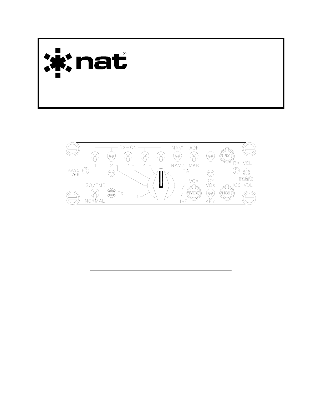
3.3 Controls and Indicators
Transceiver Receive
Audio Switches
NAV Receive
Audio Switches
Receive
Volume
Control
Mode Switch
TX/PA Select Switch
ICS Controls
The transmit and PA functions are controlled with a single rotary selector switch. The
main receive volume, ICS volume and ICS VOX squelch are individually adjusted with
rotary controls. The ICS and ISO/EMER / NORM operations are selected using colourcoded toggle switches. Individual receive audio is selected with colour-coded toggle
switches.
Dec 6, 2004 Page 3-1
ENG-FORM: 806-0106.DOT
CONFIDENTIAL AND PROPRIETARY TO NORTHERN AIRBORNE TECHNOLOGY LTD.
Page 32

AA95-766 Single Channel Audio Controller Manual SM95-766 Rev. 2.00
r
3.3.1 Receive Audio Select Switches
The transceiver receive audio select switches (white switch bats) are two position switches.
The relevant transceiver receive audio is selected ON when the switch is set to the ‘up’
position, and when set to the ‘down’ position it is selected OFF.
The NAV receive audio select switches (blue switch bats) are three position switches.
When set to the ‘up’ or ‘down’ position, the relevant NAV receive audio is selected on.
When set to the ‘centre-off’ position, the relevant NAV receive audio is selected off.
The master receive volume control (RX VOL) adjusts all receive audio concurrently from
1% to full. It is important to set the individual radio volume controls to a nominal level,
and then use the master receive volume on the audio controller to adjust for changing
flight conditions.
When the red mode switch is set to NORMAL, the passengers will hear the radio audio
as selected on the controller. The passengers will not hear any radio audio when the
red mode switch is in the ISO/EMR position. All receive audio is muted during transmit
(normal mode).
3.3.2 Transmit Selector Switch
TX Indicato
Transmit Selector Switch
The transmit selector switch is a six-position switch used to select the desired transceiver,
and when rotated fully clockwise it selects the PA function. When the hand mic or
transmit PTT switch is activated, the mic will be coupled to the radio (or PA) selected.
The pilot has priority over the copilot during transmit operations.
Receive audio for the transceiver selected is automatically activated as a function of the
rotary selector switch, and no additional switching is needed to establish outside
communication. During transmit, all audio selected is muted except the sidetone of the
transceiver in use. Direct Audio is also muted during transmit.
The front panel TX indicator will illuminate green when either the pilot or co-pilot
transmits. It will not light when the hand mic (if installed) is used.
Page 3-2 Dec 6, 2004
ENG-FORM: 806-0106.DOT
CONFIDENTIAL AND PROPRIETARY TO NORTHERN AIRBORNE TECHNOLOGY LTD.
Page 33

SM95-766 Rev. 2.00 AA95-766 Single Channel Audio Controller Manual
3.3.3 ICS Functions
The ICS controls consist of the VOX and ICS
controls, which are rotary knobs, and the ICS
VOX / KEY control, which is an orange twoposition toggle switch. The function of these
controls is outlined below.
Intercom audio may be implemented in three modes: LIVE (on constantly), VOX (voice
activated), or KEYED (active only when switched by ICS PTT cyclic or foot switch).
It is common to use the LIVE mode during ground operations, start-up, etc., and to use
VOX or KEYED operation if conditions are so noisy that ‘pilot fatigue’ will result.
LIVE (Hot Mic Operation)
ICS mode switch (orange switch bat) set to the up (VOX) position and the VOX
squelch control set to the full counter-clockwise position.
KEYED ICS (PTT Operation)
ICS toggle switch (orange switch bat) set to the down (KEY) position. Keyed ICS
is inherent to the pilot and copilot microphone circuits only. Passenger
microphone circuits will be LIVE with this mode selected.
VOX (Voice Activated)
ICS toggle switch (orange switch bat) set to the up (VOX) position. Set the ICS
VOX Squelch control fully counter-clockwise and then slowly rotate clockwise
until the intercom just becomes quiet. This setting will vary with ambient noise
conditions, and the quality and number of microphones connected in the system.
3.3.3.1 General ICS Functions
Passenger ICS audio is LIVE when the controller is in the LIVE or KEYED mode of ICS
operation. In the KEYED mode of operation the passenger microphones are LIVE.
Utilize drop cord assemblies incorporating microphone circuit interrupt switches for
keyed ICS operation. Passenger ICS is VOX triggered when VOX mode is selected.
All ICS audio is controlled by the front panel ICS volume control and may be varied to suit
conditions. In multiple station systems, the ICS volume adjusts only the incoming ICS audio
level. The ICS VOL control provides adjustment from approximately 1% to full output.
The mode switch (red switch bat) is used to select between NORMAL and ISO/EMR
modes. In the NORMAL position (down), all operations of the ICS are functional as
described above. When the switch is in the ISO/EMR (pilot isolate/emergency position),
the pilot is isolated from the rest of the passengers. If the controller is operated in the
ISO/EMR mode, ICS operation will continue (if there is no fault condition) between the
passengers and copilot, but will exclude the pilot. See section 3.4 for further details.
Dec 6, 2004 Page 3-3
ENG-FORM: 806-0106.DOT
CONFIDENTIAL AND PROPRIETARY TO NORTHERN AIRBORNE TECHNOLOGY LTD.
Page 34

AA95-766 Single Channel Audio Controller Manual SM95-766 Rev. 2.00
3.4 Emergency Operation
When the red mode switch is set to the ISO/EMR position, the pilot is removed from the
ICS bus and connected directly to the selected radios. This mode should be selected in
the event of a box fault or power failure.
In the ISO/EMR mode, all functions are retained by the pilot, except ICS and possibly
boom mic operation. If the box or airframe fault prevents the TX annunciator from
lighting during transmit (indicating a failure in the mic keying circuit), then the hand mic
should be used. A power fault of any kind will prevent the TX annunciator from lighting,
giving an immediate indication of failure. If ICS audio is still available, then the power to
the controller has not failed, and loss of the TX light indicates TX switch failure.
In the ISO/EMR mode, all switches work exactly as they do during NORMAL operation,
except for the RX and ICS volume controls, which have no effect.
The ISO/EMR function should be tested prior to flight to ensure proper operation, and
allow the radio levels to be set adequately for emergency operation.
Any selected receive audio is switched to the primary user (pilot) in the ‘emergency’
mode, but not to any passengers in the system. Audio level will be lower than in
NORMAL operation because the signals are obtained directly from the radios, bypassing
the electronics in the controller. This is provided for failure situations that make operation
impossible in the NORMAL mode (i.e. loss of power or amplifier failure, etc.)
3.5 Direct Audio
Direct Audio is an audio signal from an existing warning system that is connected
‘directly’ into the audio system, and is not front-panel selectable. The Direct Audio
signal is an amplified input, and can be adjusted at the time of installation (see section
2.3.4.2).
End of Section 3
Page 3-4 Dec 6, 2004
ENG-FORM: 806-0106.DOT
CONFIDENTIAL AND PROPRIETARY TO NORTHERN AIRBORNE TECHNOLOGY LTD.
Page 35

This page intentionally left blank
 Loading...