

Page 1
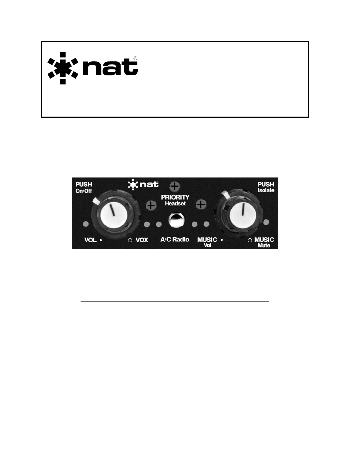
SM48
AA86/87
Stereo Intercom
INSTALLATION AND OPERATION MANUAL
REV 4.00 November 12, 2003
Northern Airborne Technology Ltd.
1925 Kirschner Road
Kelowna BC, Canada
V1Y 4N7
Telephone (250) 763-2232
Facsimile (250) 762-3374
Copyright 2003 by Northern Airborne Technology
CONFIDENTIAL AND PROPRIETARY TO NORTHERN AIRBORNE TECHNOLOGY LTD.
Page 2
SM48 Rev 4.00 AA86/87 Stereo Intercom Manual
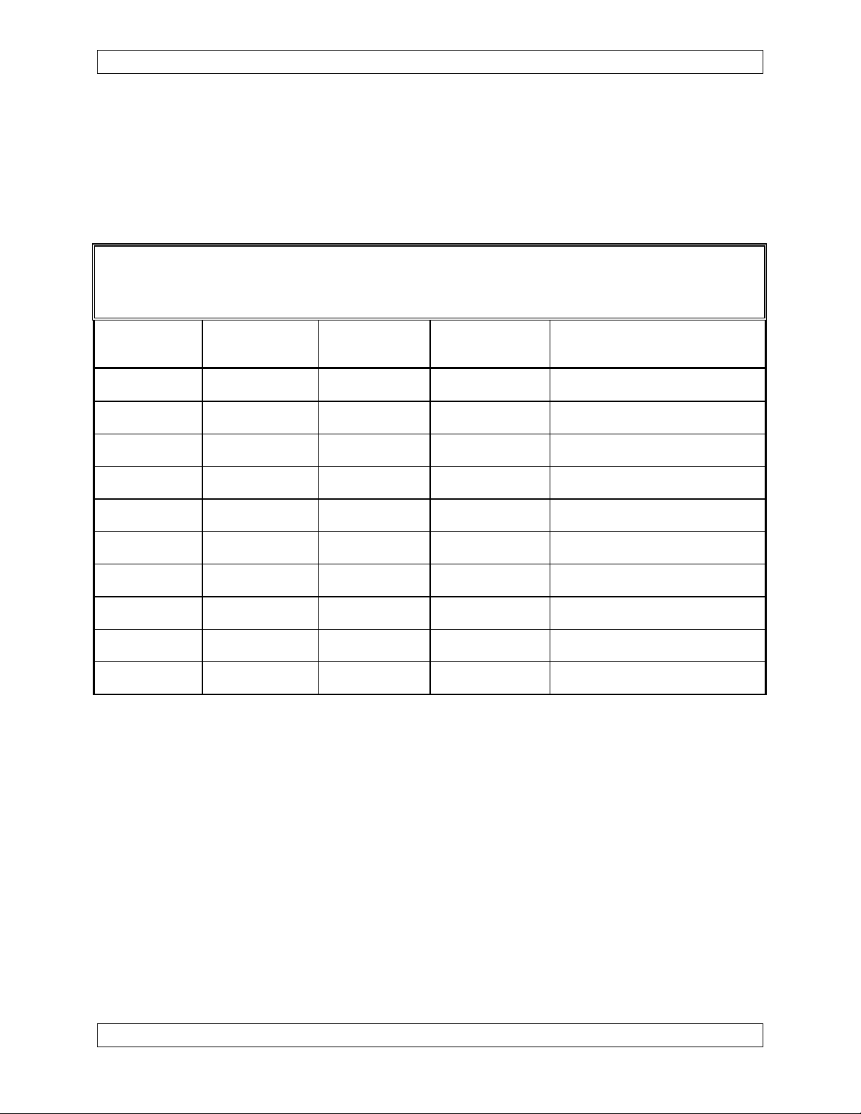
Periodically NAT will release manual amendments. In order to maintain the most
accurate and up to date manual these amendments should be carried out immediately
upon receipt and recorded on the following amendment record.
AMENDMENT RECORD
Amendment
Number
Amendment
Date
Section(s)
Changed
Date
Entered
Entered By
Insert any Amendment Instruction sheets after this page.
Nov 12, 2003 Page ii
ENG-FORM: 820-0109.DOT
CONFIDENTIAL AND PROPRIETARY TO NORTHERN AIRBORNE TECHNOLOGY LTD.
Page 3

SM48 Rev 4.00 AA86/87 Stereo Intercom Manual
Table of Contents
Section Title Page
1.0 Description
1.1 Introduction 1-1
1.2 Purpose of Equipment 1-1
1.3 Features 1-1
1.4 Specifications 1-2
1.4.1 Electrical Specifications 1-2
1.4.2 Physical Specifications 1-2
2.0 Installation
2.1 Introduction 2-1
2.2 Unpacking and Inspection 2-1
2.2.1 Installation Kit Components. 2-1
2.3 Installation Procedures 2-2
2.3.1 Warnings 2-2
2.3.2 Cautions 2-2
2.3.3 Cabling and Wiring 2-2
2.3.4 Electrical Installation 2-3
2.3.5 Stereo Inputs 2-4
2.3.6 Mechanical Installation 2-7
2.4 Post-Installation Checks 2-8
2.4.1 Voltage/resistance checks 2-8
2.4.2 Power On checks 2-8
2.5 Continued Airworthiness 2-8
2.6 Installation Drawings 2-9
3.0 Operation
3.1 Introduction 3-1
3.2 Controls and Indicators 3-1
3.2.1 On/Off, Volume and Vox controls. 3-1
3.2.2 PRIORITY Control 3-2
3.2.3 MUSIC Vol, MUSIC Mute and Isolate Controls 3-3
3.2.4 Active Microphone LEDs 3-4
3.2.5 External Controls 3-4
3.3 EMERGENCY OPERATION 3-5
Nov 12, 2003 Page iii
ENG-FORM: 820-0109.DOT
CONFIDENTIAL AND PROPRIETARY TO NORTHERN AIRBORNE TECHNOLOGY LTD.
Page 4

SM48 Rev.4.00 AA86/87 Stereo Intercom Manual
Section 1.0 Description
1.1 Introduction
This manual contains information on the AA86/87 Stereo Intercom.
Information in this section consists of purpose of equipment, features and specifications.
1.2 Purpose of Equipment
The AA86/87 series of stereo intercoms provide versatility and performance in a compact,
user-friendly panel mounted system. The AA86 and AA87 series are available in 2, 4 or 6
place models, which gives the flexibility to choose the most suitable system for specific
requirements. Up to 6 positions are available without the need to add expansion modules
or multiplex systems. Full transmit and intercom capability for pilot and co-pilot is
provided, with intercom functions for up to four additional passengers.
1.3 Features
The AA86 and AA87 feature a system volume control for adjusting ICS and radio levels,
mic squelch control, music muting level, and music volume. A bi-colored LED indicates
On/Off and Pilot transmit, while another bi-colored LED indicates Pilot Isolate mode and
Co-pilot transmit. There are four red LED's (two on 2-position models) indicating ICS
microphone activity for pilot, co-pilot, and passengers 1 and 2.
The AA86 and AA87 employ NAT’s exclusive Digitrac ‘Auto-tracking’ squelch (to keep
the microphone squelch setting at the right level during shifts in cockpit noise), and an
Automatic Volume Reduction (AVR) system (which allows the pilot to instantly select
either ATC or intercom as priority communications source). The AVR system places
the less critical source at a partially muted level for monitoring purposes.
The AA87 (only) can provide Crew Mode capability by installing a remote switch in a
convenient location on the instrument panel. This enables the intercom system to be split
into two independent groups, so that the flight crew can perform radio communication
operations without interruptions from passenger intercom, and the passengers can
converse without stopping whenever the flight crew needs to hear the radio.
The AA86 and AA87 intercoms support various stereo music sources such as portable
tape or CD players, line level and speaker outputs.
The AA86 and AA87 allow the pilot to control the level of muting to suit the situation.
The pilot can choose from a range of full muting during critical communications to none
at all.
Nov 12, 2003 Page 1-1
ENG-FORM: 800-0106.DOT
CONFIDENTIAL AND PROPRIETARY TO NORTHERN AIRBORNE TECHNOLOGY LTD.
Page 5

AA86/87 Stereo Intercom Manual SM48 Rev. 4.00
An audible warning to the pilot and co-pilot is triggered if any transmitter is keyed for
more than 30 seconds. (This usually indicates a stuck microphone condition.)
In the event that failure occurs in the power source to the AA86 and AA87, the Fail-safe
mode activates automatically, routing the pilot's headset directly to the audio panel or
radio source. If a partial failure occurs within the intercom, it can be manually switched
to the Fail-safe mode by turning the system off.
1.4 Specifications
1.4.1 Electrical Specifications
Inputs:
Power 10 - 32 Vdc @ 0.25 A nominal
Microphones 2/4/6 standard carbon or carbon equivalent (250 mVrms full
output, 150 Ω). Individual gating with adjust depth
Music 1 stereo input (AA86) - 2 stereo inputs (AA87)
(Compatible) Portable Tape/CD, & CD changers with low level pre-amp/
CD Line output
Radio 1 kΩ, 2.5 Vrms
Outputs:
Headset Up to 6 channels @ 100 mW/channel max.
Impedance 4 - 600 Ω
Frequency Resp. 20 Hz - 20 kHz
Distortion Less than 1% THD @ 75 mW/150 Ω
Lamps 2 bi-colored LED’s - On/Off and Pilot transmit
Pilot Isolate and Co-pilot transmit
4 red LED's on 4 and 6 position models -
ICS microphone activity for Pilot,
Co-pilot, and passengers 1 and 2
2 red LED's on 2 position models -
ICS microphone activity for Pilot
and Co-pilot
1.4.2 Physical Specifications
Height 1.1” (28 mm)
Length 5.7” (144 mm) behind panel
Width 3.3” (83 mm)
Weight 0.58 lbs. (260 g)
Mounting Panel mount, vertical or horizontal
End of section 1.0
Page 1-2 Nov 12, 2003
ENG-FORM: 800-0106.DOT
CONFIDENTIAL AND PROPRIETARY TO NORTHERN AIRBORNE TECHNOLOGY LTD.
Page 6
SM48 Rev. 4.00 AA86/87 Stereo Intercom Manual
Section 2.0 Installation
2.1 Introduction
Information in this section consists of: unpacking and inspection procedures, installation
procedures, post-installation checks, and installation drawings.
Important Note:
The AA86/87 with NAT faceplates IS NOT
mechanically interchangeable with the previous
QuietFlite version. Mounting holes must be relocated
for retrofit, and installation procedure changes noted.
2.2 Unpacking and Inspection
Unpack the equipment carefully and locate the warranty card. Inspect the unit visually
for damage due to shipping and report all such claims immediately to the carrier
involved. Note that each unit should have the following:
- AA86/87 Stereo Intercom
- Warranty Card
- Release certification
- Installation Kit
- Operator’s Manual
Verify that all items are present before proceeding and report any shortage immediately
to your supplier.
Complete the warranty card information and send it to NAT when the installation is
complete. If you fail to complete the warranty card, the warranty will be activated on
date of shipment from NAT.
2.2.1 Installation Kit Components.
The contents of the NAT AA86/87 Installation Kit are itemised below:
Quantity Description NAT Part #
1 Faceplate, Reversible Horiz./Vert. 50-04-041
2 Knob, Fluted Concentric, Rubber 40-21-041
1 Hoods, D-sub, Plastic 20-29-026
1 Connector, D-sub, Socket, solder 20-20-026
2 Locking Hardware, D-sub, Latch Plate 20-27-026
3 Screw, Panhead, Phillips, Brass, Black 25-11-427
1 Label, Drill Template, AA86/87 43-10-086
Nov 12, 2003 Page 2-1
ENG-FORM: 805-0104.DOT
CONFIDENTIAL AND PROPRIETARY TO NORTHERN AIRBORNE TECHNOLOGY LTD.
Page 7

AA86/87 Stereo Intercom Manual SM48 Rev. 4.00
2.3 Installation Procedures
2.3.1 Warnings
Do not bundle any lines from this unit with transmitter coax lines. Do not bundle any
audio or DC power lines from this unit with 400 Hz synchro wiring or AC power lines. Do
not position this unit or wiring from this unit next to any device with a strong alternating
magnetic field such as an inverter, or significant audio interference will result.
2.3.2 Cautions
⇒ In all installations, connect exactly as shown and ground as indicated. Significant
ground loop and noise problems may result from not following these guidelines.
⇒ Do not connect the microphone and headphone shields together.
⇒ Use caution when routing microphone and ICS wiring as they use low level signals
prone to coupling from other sources.
⇒ Do not take a ground from the instrument panel or similar location that shares a
ground return with a turn and bank, horizon or other motor driven instrument. This
may cause the Intercom unit to pick up the sound of the motor as ground loop
interference.
⇒ The AA86/87 Intercom should not be connected through the avionics master
switch as it is generally desirable to have the intercom available at all times, even
when the avionics are off.
2.3.3 Cabling and Wiring
For shielded wire applications, use Tefzel Mil-M-27500 or Mil-M-81044 shielded wire
with solder sleeves (for shield terminations) to make the most compact and easy to
terminate interconnect. Follow the wiring diagrams in Section 2.6 as required.
Allow 3 inches from the end of the wire to the shield termination to allow easy
installation of the hood. Note that the hood is a ‘clamshell’ hood, and is installed after
the wiring is complete.
All wiring should be at least 22 AWG, except power and ground lines, which should be
at least 20 AWG. Ensure that all ground connections are clean and well secured.
To prevent system failure or inadequate equipment protection, supply power from a
separate 1.0 A breaker or fuse, not connected to any other source.
Page 2-2 Nov 12, 2003
ENG-FORM: 805-0104.DOT
CONFIDENTIAL AND PROPRIETARY TO NORTHERN AIRBORNE TECHNOLOGY LTD.
Page 8
SM48 Rev. 4.00 AA86/87 Stereo Intercom Manual
2.3.4 Electrical Installation
The AA86/87 Stereo Intercoms employ a single, common ground at Pins 14 and 15.
Ground returns may be tied together and connected to either ground pin.
2.3.4.1 Power
The DC power source (aircraft power or battery, between +10 and +32 volts) must be
connected at Pin 1. Nominal ‘on’ current drain is in the order of 100 ma (175 ma for the
AA87) with peak currents generally less than 0.25 ampere.
2.3.4.2 Microphone
Each microphone (up to six) must be wired to separate mic inputs as follows:
All Models -004 and –006 models only –006 models only
Position
Pin #
Position
Pin #
Position
Pin #
Pilot 25 Passenger Mic #3 4 Passenger Mic #5 16
Co-Pilot 24 Passenger Mic #4 5 Passenger Mic #6 17
Passenger mics may be wired to any location within the aircraft cabin and are
interchangeable. Pilot and Co-Pilot mic 'identities', however, must be properly
maintained to assure proper transmit audio routing during Push-To-Talk (PTT), Pilot
Isolate, and Fail Safe functions.
2.3.4.3 Headphones
Refer to Interconnect drawing AA86\403-0 for full headphone connection specifics.
The Pilot headphones must be wired to Pins 12 and 13 (left and right channels,
respectively) to assure proper Pilot Isolate and Fail-Safe operation. The Co-Pilot
headphones must be wired to Pins 20 and 21 (left and right channels, respectively) to
assure proper CREW Mode operation (CREW Mode is available only on AA87 Models). All
other headphones should be wired to Pins 8 and 9 (left and right channels, respectively).
The AA86/87 can support up to 20 standard aviation headphones. The Intercom output
is a low impedance source that permits direct connection to consumer stereo
headphones (typically between 8 and 50 ohm) as well as standard aviation headphones
(300 ohm). No matching transformers or other specialized connection systems are
required for any headphone impedance within the range of 4-600 ohm.
Headphones of differing impedances may be mixed (e.g. 8 ohm consumer and 300 ohm
aviation) so long as consideration is given to the fact that the lower impedance
headphones (8 ohm consumer) will produce more output (volume) for a given Intercom
volume setting. Therefore, consumer headphones with built-in volume controls should
be employed.
Nov 12, 2003 Page 2-3
ENG-FORM: 805-0104.DOT
CONFIDENTIAL AND PROPRIETARY TO NORTHERN AIRBORNE TECHNOLOGY LTD.
Page 9

AA86/87 Stereo Intercom Manual SM48 Rev. 4.00
2.3.4.4 Stereo versus Monaural Headset
The NAT AA86/87’s are full stereo intercom systems. Left and right channels are
provided for Pilot, Co-Pilot, and Passenger headset output positions. Monaural input
sources such as the aircraft radios and the voice/microphone inputs are split and
appear equally in both the Left and Right channel outputs. Therefore, when wiring the
AA86/87 Intercom for monaural operation, headset connection need be made to only
one of the two outputs, either Left or Right channel. DO NOT CONNECT THE TWO
OUTPUTS TOGETHER, simply leave the unused channel output unterminated.
2.3.4.5 Comm Radio Receive Audio
The AA86/87 Intercoms require a ‘headphone’ level radio audio signal. The audio panel
headphone output (or direct navcom audio if no audio panel is installed) must be wired
to Pin 22.
2.3.4.6 Comm Radio Transmit Audio
The AA86/87 Intercoms require connection to the comm radio(s) mic input. Pin 23 must
be wired to the audio panel microphone input (or directly to the comm radio if no audio
panel is installed).
2.3.4.7 Push-To-Talk (PTT)
The pilot’s yoke-mounted or other aircraft Push-To-Talk (PTT) switch should be
connected in parallel to the AA86/87 (at Pin 11) and to the aircraft comm key input (i.e.
audio panel or comm radio PTT input, as appropriate). If the aircraft is equipped with a
second (Co-Pilot) PTT switch, this switch should be connected directly to the AA86/87
at Pin 10.
2.3.4.9 CREW/ALL Switching (AA87 Models Only)
An external SPST switch is required for CREW/ALL selection. Pin 18 must be
grounded (i.e. switch 'closed') to enter the ALL Mode. CREW Mode is selected by
ungrounding Pin 18 (i.e. Switch 'open').
2.3.5 Stereo Inputs
2.3.5.1 AA87 Models
Separate Stereo inputs are provided for the front (crew) and rear (passenger) seats.
Front seat inputs are Pins 6 and 7 (left and right channels, respectively). Rear seat
inputs are Pins 2 and 3 (left and right channels, respectively).
If a single stereo source is desired to feed the same stereo music to all seats, ‘jumper’
left channel Pins 2 and 6 and right channel Pins 3 and 7 together.
Page 2-4 Nov 12, 2003
ENG-FORM: 805-0104.DOT
CONFIDENTIAL AND PROPRIETARY TO NORTHERN AIRBORNE TECHNOLOGY LTD.
Page 10

SM48 Rev. 4.00 AA86/87 Stereo Intercom Manual
a) Selective disabling of Music
Appropriate on/off switch(es) should be wired between the stereo source and each of
the stereo inputs. This permits the pilot to selectively disable music listening to either
the front or rear seats while the remaining positions receive uninterrupted audio.
If separate stereo sources are provided for the front and rear seats, each source may
be fixed/hardwired to the respective front and rear seat input.
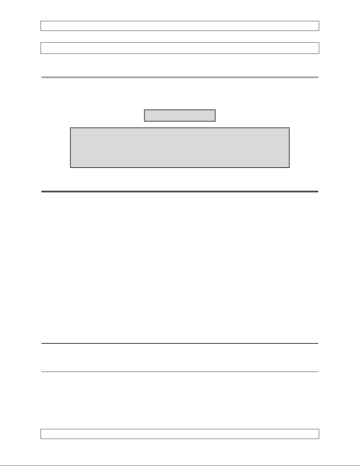
b) Two Stereo Sources
Alternatively, if two stereo sources are to be used, we recommend wiring a DPDT
center-off switch to each input. This permits great flexibility in music listening - either
front or rear seating position can independently select to listen to either music source or
to select the 'no music' center-off position. (See figure 1, below).
Crew
Music Select
R
From
M usic Source 1
L
7
Crew Music
In p ut P ins
6
Passenger
Music Select
3
R
From
Music Source 2
L
Use ‘Center-off’ switches - Center P osition = M usic Off
Passenger
In p ut P ins
2
Music
Figure 1
c) Low Power Inputs
All stereo inputs are low-level (i.e. line) inputs designed to be driven from nearly any
stereo source including, in particular, battery operated tape and CD players. When using
one of these low power, battery-operated units, it is preferable to connect the AA86/87 to
the stereo's headphone outputs (rather than the 'line' output) to assure proper operation
of the stereo's volume controls. If use of a portable tape or CD player is contemplated, the
installer may wish to consider placing a stereo jack in the aircraft panel (wired directly to
the AA86/87’s stereo inputs) to enable the pilot to plug the portable stereo player directly
into the panel.
Nov 12, 2003 Page 2-5
ENG-FORM: 805-0104.DOT
CONFIDENTIAL AND PROPRIETARY TO NORTHERN AIRBORNE TECHNOLOGY LTD.
Page 11

AA86/87 Stereo Intercom Manual SM48 Rev. 4.00
µ
µ
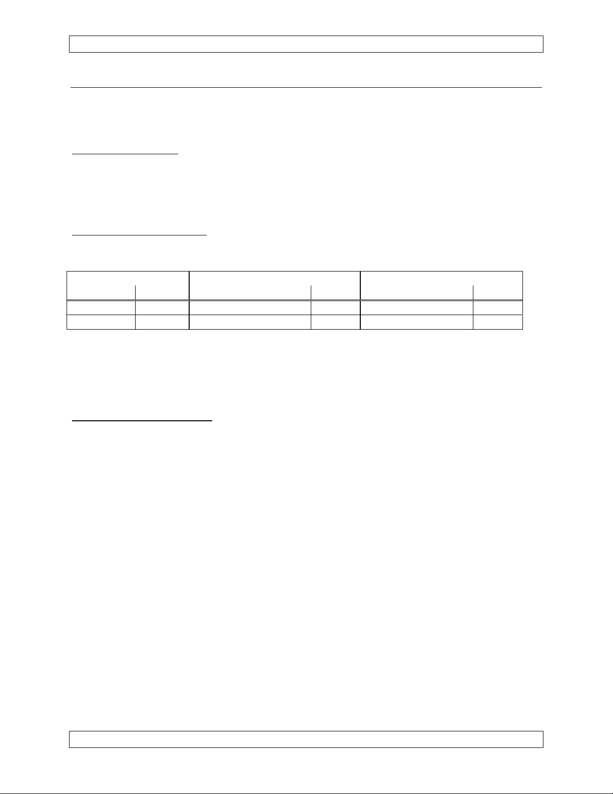
The speaker-level outputs from conventional car-type stereo sources may also be
connected to the AA86/87 Intercom stereo inputs with the following cautions. First,
some automotive stereos do not permit grounding the negative or return speaker
connection. To overcome this problem, a 0.22uf capacitor (preferably a non-polarized
Mylar or equivalent) may be placed between the negative output lead from each
channel and Intercom ground (see figure 2, below).
Stereo Music Source
AA86 or AA87
Intercom Input
Spkr +
Left Speaker Output
Spkr -
Spkr +
Right Speaker Output
Spkr -
R1
22
R3
22
R2
R4
4-22
C1
0.22
4-22
C2
0.22
f
f
2 or 6
14, 15
3 or 7
14, 15
Figure 2
Second, the speaker level output from a conventional automotive radio is greater than
required for AA86/87 operation (this high level won't damage the AA86/87 - it just
makes stereo volume adjustment awkward). It is therefore recommended that the
speaker outputs be routed through a simple two-resistor ‘L’ attenuator as shown in
Figure 2. These resistors will also function as nominal 'loads' for the speaker outputs as
the AA86/87 stereo inputs are high impedance, e.g. about 4.7K, and are therefore not
intended to, and do not, match or load the automotive radio speaker output.
All resistors may be 22 ohm, 1/2 watt. If additional attenuation is desired/required, the
shunt resistors may be lowered to 10 ohm, 4.7 ohm, or as required.
d) Stereo Inputs to monaural Headsets
If the AA86/87 Intercom has not been wired for stereo headsets, only one of the two
stereo channels will be heard in the user's monaural headsets (both ears, but still only
one channel). To listen to stereo music sources, without wiring the intercom for stereo
operation, it will be necessary to 'combine' the Left and Right channel outputs from the
stereo music source and to connect this combined, now monaural, music source to the
appropriate Left or Right channel stereo inputs. Where the monaural headsets are wired
to the ‘left channel’ headset outputs, then the combined monaural music source must be
connected to the corresponding ‘left channel’ music inputs.
Page 2-6 Nov 12, 2003
ENG-FORM: 805-0104.DOT
CONFIDENTIAL AND PROPRIETARY TO NORTHERN AIRBORNE TECHNOLOGY LTD.
Page 12

SM48 Rev. 4.00 AA86/87 Stereo Intercom Manual
The Left and Right channel outputs of the stereo source should not be directly
interconnected to achieve this combination - these channels should be summed through
100 ohm series resistors.
The output from each channel of a battery-operated portable stereo source, or the
speaker output of a car-type player (after the optional attenuation discussed above)
should be connected to the ‘input’ ends of each resistor. The ‘output’ ends of each
resistor should be connected together and to the selected Left or Right channel stereo
inputs of the AA86/87 Intercom. Separate Stereo inputs are provided for the crew (front)
on pins 6 and 7, and passengers (rear) on pins 2 and 3.
2.3.5.2 AA86 Models
The AA86 Intercom has only one set of stereo inputs. The stereo source must be
connected to the front music inputs at Pins 6 and 7. Music will be heard in all
headphones, both front and rear.
2.3.6 Mechanical Installation
The AA85-001 InterVox Intercom can be installed either horizontally or vertically.
For proper installation, refer to the Mounting Diagram (AA87\920-0) and the following
steps:
1) After selection of an appropriate panel location, drill the required mounting holes in
the aircraft panel referencing the drill template provided in the installation kit.
2) Carefully insert the AA86/87 from behind the panel, sliding the control switches
through the relevant holes. Ensure that all the LED’s are visible through the panel
holes.
3) Position the metal faceplate over the control shafts (vertically or horizontally lettered
outward, as appropriate). Note: Ensure that the AA86/87 and faceplate are both
positioned tightly against the aircraft panel.
4) Secure the intercom to the aircraft panel with the three 6-32 panhead screws provided.
5) Rotate the shaft of each outer potentiometer fully counterclockwise. Align the light
grey marker of each outer concentric knob to the ‘7 o’clock’ position, matching the
flats on the bushing with the corresponding flats on the inside of the knob, and
press firmly into position.
6) Rotate the shaft of each inner potentiometer fully counterclockwise. Align the black
marker of each inner concentric knob with the outer knob marker, and press firmly
into position.
Nov 12, 2003 Page 2-7
ENG-FORM: 805-0104.DOT
CONFIDENTIAL AND PROPRIETARY TO NORTHERN AIRBORNE TECHNOLOGY LTD.
Page 13

AA86/87 Stereo Intercom Manual SM48 Rev. 4.00
2.4 Post-Installation Checks
2.4.1 Voltage/resistance checks
Do not attach the AA86/87 until the following conditions are met.
Check the following:
a) Check P1, pin <1> for +10 to +32 Vdc relative to ground.
b) Check P1, pins <14> and <15> for continuity to ground (less than 0.5 Ω).
2.4.2 Power On checks
Install the AA86/87 and power up the ship’s comm/nav systems. Verify normal
operation of all functions. Refer to Section 3 for specific operation details.
a) Begin with only the pilot's headset installed. Check for correct radio operation
both receive and transmit. Check yoke (or cyclic) switch action.
b) If there is a music source in the system turn it on and verify that music is heard in
all modes except Pilot Isolate. Check for proper mute operation.
Note: Unusual buzzes, hums or other background audio are symptomatic of
multiple grounds, or noisy external systems such as blowers or pumps
sharing wiring with the audio system. Failure to key or correctly modulate
a transmitter is often the result of forgetting to connect all required
grounds to the radio or external audio system.
c) Plug in the copilot's headset. Check for correct ICS operation. Check yoke
switch functions, if installed.
d) Plug in any remaining headsets, and check for correct ICS operation.
Note: Incorrect jack wiring is a common fault for rear passenger stations, and
may cause a wide range of problems.
e) To verify proper operation, all functions and levels should be checked in-flight.
2.5 Continued Airworthiness
Maintenance of the AA86/87 Stereo Intercom is ‘on condition’ only. Periodic
maintenance of this product is not required.
Page 2-8 Nov 12, 2003
ENG-FORM: 805-0104.DOT
CONFIDENTIAL AND PROPRIETARY TO NORTHERN AIRBORNE TECHNOLOGY LTD.
Page 14

SM48 Rev. 4.00 AA86/87 Stereo Intercom Manual
2.6 Installation Drawings
DRAWING REV. DESCRIPTION TYPE
AA86\403-0 1.10 Odyssey/Intrepid Stereo Intercom Interconnect
AA86\405-0 1.01 Odyssey/Intrepid Stereo Intercom Connector Map
AA86\905-0 1.00 Odyssey/Intrepid Stereo Intercom Faceplate
AA86\920-0 1.10 Odyssey/Intrepid Stereo Intercom Mounting Diagram
AA86\922-0 1.00 Odyssey/Intrepid Stereo Intercom Mech. Installation
4310086\900-0 1.10 AA86/87 Drill template Label Orthographic
Section 2.0 ends after these Drawings
Nov 12, 2003 Page 2-9
ENG-FORM: 805-0104.DOT
CONFIDENTIAL AND PROPRIETARY TO NORTHERN AIRBORNE TECHNOLOGY LTD.
Page 15

Page 16

Page 17

Page 18

Confidential and Proprietary to NAT
Page 19

Page 20

Page 21

SM48 Rev. 4.00 AA86/87 Stereo Intercom Manual
(
(
)
Section 3.0 Operation
3.1 Introduction
Information in this section consists of the functional and operational procedures for the
AA86/87 Stereo intercom.
3.2 Controls and Indicators
Pilot Isolate and
Co-Pilot PTT Indicator LED
MUSIC Vol, MUSIC Mute and Isolate Controls
(Section 3.2.3)
PRIORITY Control
Section 3.2.2
On/Off, VOL and
VOX Control
Section 3.2.1)
Intercom and
Pilot PTT
Indicator LED
Active Microphone LED’s
Section 3.2.4
AA86/87 - Vertical Configuration AA86/87- Horizontal Configuration
3.2.1 On/Off, Volume and Vox controls.
The Volume, Vox and Power controls are dual concentric potentiometer assemblies with
an integral push on/push off switch.
3.2.1.1 On/Off Switch
The On/Off function of the intercom is operated by pushing the smaller (inner) portion of
this knob. Each switching action will change the state of the intercom, and the LED
lamp located below and to the left of the On/Off switch (when the intercom is in its
horizontal position) will illuminate green when the intercom is on. (This lamp additionally
functions as a pilot PTT indicator and will turn red upon Pilot PTT actuation.)
The pilot's microphone and headphones are automatically routed directly to the audio
panel when the AA86/87 is placed in the off position.
Nov 12, 2003 Page 3-1
ENG-FORM: 806-0104.DOT
CONFIDENTIAL AND PROPRIETARY TO NORTHERN AIRBORNE TECHNOLOGY LTD.
Page 22

AA86/87 Stereo Intercom Manual SM48 Rev. 4.00
3.2.1.2 Main Volume Control (VOL)
The main Volume control sets the overall Radio/ICS volume level for all headsets.
Rotating the control clockwise increases both the ICS (intercom) and radio volumes,
and counterclockwise rotation will reduce these volumes.
It is recommended that the volume be set to the highest level that any aircraft occupant
might find comfortable during normal in-cockpit conversation. If this level is too loud for
a particular user, the individual headphone volume controls may be adjusted to a
personally comfortable level.
3.2.1.3 VOX Control
The VOX Control selects the mode of operation of the intercom microphones. When
the control is in the centre of its range, the intercom is in the VOX mode (voice
activated). As the control is rotated clockwise, the system becomes more sensitive, until
in the fully clockwise position it is in HOT mode (on constantly). As the control is rotated
counterclockwise, the sensitivity decreases.
Each microphone connection is provided with a separate automatically tracking squelch
circuit that requires little adjustment once the original squelch sensitivity is set.
3.2.2 PRIORITY Control
The PRIORITY control is a three position switch that enables the pilot to select between
Headset, Off and A/C Radio to prioritize AA86/87 inputs according to flight conditions.
3.2.2.1 Headset PRIORITY
When the PRIORITY switch Headset position is selected, intercom users are given
priority over the aircraft radios. The AA86/87 muting circuit lowers the radio audio and
music level to allow the intra-cabin conversation to be clearly audible. However, since
the radio audio is not completely muted, a 'watch' is maintained on the selected radio.
3.2.2.2 A/C Radio PRIORITY
When the PRIORITY switch is in the A/C Radio (aircraft radio) position, the radio audio
has priority over intra-cabin conversation. In this position, the muting circuit lowers the
intercom voice audio whenever an aircraft radio audio is received.
3.2.2.3 OFF
When the PRIORITY switch is in the centre or ‘Off’ position, both the radio audio and
intercom voice inputs have equal priority. Both audio sources are combined and will be
heard equally (unless otherwise set by the AA86/AA87 and Comm radio volume controls). In
this mode, it may be difficult to understand either audio source as both will be heard together.
Page 3-2 Nov 12, 2003
ENG-FORM: 806-0104.DOT
CONFIDENTIAL AND PROPRIETARY TO NORTHERN AIRBORNE TECHNOLOGY LTD.
Page 23

SM48 Rev. 4.00 AA86/87 Stereo Intercom Manual
3.2.3 MUSIC Vol, MUSIC Mute and Isolate Controls
The MUSIC Vol, MUSIC Mute and Isolate controls are dual concentric potentiometer
assemblies with an integral push on/push off switch.
3.2.3.1 Music Volume
The automatic music muting feature of the AA86/87 intercom makes it necessary to set
the initial/maximum music volume when neither the radio audio nor any microphone
input is active. Alternatively, the Music Mute control may be rotated to its non-muting,
fully clockwise position. (See section 3.2.3.2)
If the stereo music source also includes a volume control, it is recommended that the
AA86/87 Music Volume control is set at a nominal position, and that further volume
changes be made by adjusting the control provided on the music source.
3.2.3.2 MUSIC Mute
Rotating the Music Mute control fully clockwise gives minimum music muting (i.e. full
music volume) and full counterclockwise rotation represents maximum muting (i.e. total
muting or zero music volume).
The interaction between the Music Volume and Music Mute controls described in
section 3.2.3.1 requires that the initial (maximum) music volume should be set prior to
setting the music mute level.
The Music Mute control determines the depth of muting; that is, the music volume when
the radio audio is active and/or when someone in the aircraft is speaking on the
intercom. The Music Mute control may be adjusted for the desired 'background' level
when either the radio audio input or any intercom mic is active.
3.2.3.3 Pilot Isolate
The Isolate function of the intercom is controlled by pushing the smaller (inner) portion of
this knob. Each switching action will change the state of the AA86/87 between the
isolate and non-isolate configurations, and the indicator lamp located to the right and
below the Pilot Isolate switch (when the intercom is in its horizontal position) illuminates
green to indicate that Pilot Isolate mode has been selected. This indicator also
functions as a Co-Pilot PTT indicator, and lights red during Co-Pilot PTT operation.
Pilot Isolate functions to completely isolate the pilot from the passengers (including the
co-pilot). The pilot will not hear any other lntercom user or music. Similarly, the co-pilot
and remaining users, while hearing each other and the music, will not hear the pilot or
the radio audio.
Nov 12, 2003 Page 3-3
ENG-FORM: 806-0104.DOT
CONFIDENTIAL AND PROPRIETARY TO NORTHERN AIRBORNE TECHNOLOGY LTD.
Page 24

AA86/87 Stereo Intercom Manual SM48 Rev. 4.00
3.2.4 Active Microphone LEDs
The microphone squelch circuits are provided with an activity LED, which illuminates
red to indicate when the associated microphone is active. (There are two indicator
lamps for the two position models, and four indicator lamps on the four and six position
models - no lamps are provided for microphone/squelch 5 and 6 on six-place models.)
3.2.5 External Controls
3.2.5.1 Setting Input Volumes
The radio audio volume is set by adjusting the controls provided on the various aircraft
radios. To ensure proper operation of the PRIORITY functions (see section 3.2.2), this
volume should be set to match the level of the in-cockpit voice volume when the Priority
switch is in the center-off position.
The music volume is set by adjusting the control on the stereo source. Normally, the
stereo volume is adjusted for the desired listening level without muting or music volume
reduction (i.e. when neither the radio audio input nor any of the intercom microphone
inputs are active). As the music mute lowers the volume, this setting should correspond
to the loudest desirable listening level.
3.2.5.2 CREW/ALL (AA87 Models only)
The CREW/ALL modes are controlled through an external switch. Closing the switch
places the intercom in the ALL Mode. Otherwise, CREW Mode operation results.
ALL Mode
In the ALL Mode, all aircraft occupants (i.e. pilot, co-pilot and passengers) are 'tied
together', that is, they may talk to each other and they hear the same audio. Any
intercom conversation will automatically mute all music inputs and the radio audio input
(if the Priority control is set to the Headset Priority position). If the Priority is set to the
A/C Radio, the radio audio will automatically mute all in-cockpit conversation.
There are two exceptions to this. In Pilot Isolate Mode, the pilot is removed from the
intercom as explained in section 3.2.3.3 above.
The second exception is the music. If the AA87 has been set up to give separate front
and rear seat music sources, the crew and passengers will hear different music,
although the intercom is in the ALL Mode.
CREW Mode
CREW Mode separates crew and passenger conversations and removes the radio
audio from the passenger positions. The passengers may talk to each other and hear
their music input. The Crew continue to hear the aircraft radios. Passenger
conversation will not cause muting of any front seat input (i.e. music or aircraft radios)
and, similarly, the radio audio and Crew conversation will not mute any passenger input
(i.e. music or conversation).
Page 3-4 Nov 12, 2003
ENG-FORM: 806-0104.DOT
CONFIDENTIAL AND PROPRIETARY TO NORTHERN AIRBORNE TECHNOLOGY LTD.
Page 25

SM48 Rev. 4.00 AA86/87 Stereo Intercom Manual
3.2.5.3 Stuck Mic Detector
The AA86/87 Stuck Mic Detector is automatic and therefore includes no front panel
switches or controls. An audible 'beeping' will be heard in both pilot and co-pilot
headsets if either pilot or co-pilot Push-To-Talk has been depressed for more than 30
seconds. If it is desired to continue transmitting when this audible warning is heard,
momentarily release the PTT button to reset the ‘Stuck Mic’ Detector timer.
3.3 EMERGENCY OPERATION
The NAT AA86/87 intercom incorporates a fully automatic Fail-Safe circuit that
automatically, and without pilot intervention, switches the pilot’s headset (including
microphone) directly to the aircraft radios in the event of loss of intercom power and
most other critical intercom failure conditions.
IT IS POSSIBLE THAT CERTAIN RARE FAILURE MODES WILL NOT TRIGGER
AUTOMATIC FAIL-SAFE OPERATION. Upon detection of an intercom/communication
failure, simply TURN THE INTERCOM OFF to restore full Fail-Safe operation and to
ensure direct connection of the pilot’s headset to the avionics equipment.
End of section 3.0
Nov 12, 2003 Page 3-5
ENG-FORM: 806-0104.DOT
CONFIDENTIAL AND PROPRIETARY TO NORTHERN AIRBORNE TECHNOLOGY LTD.
 Loading...