

Page 1
SM38
AA85
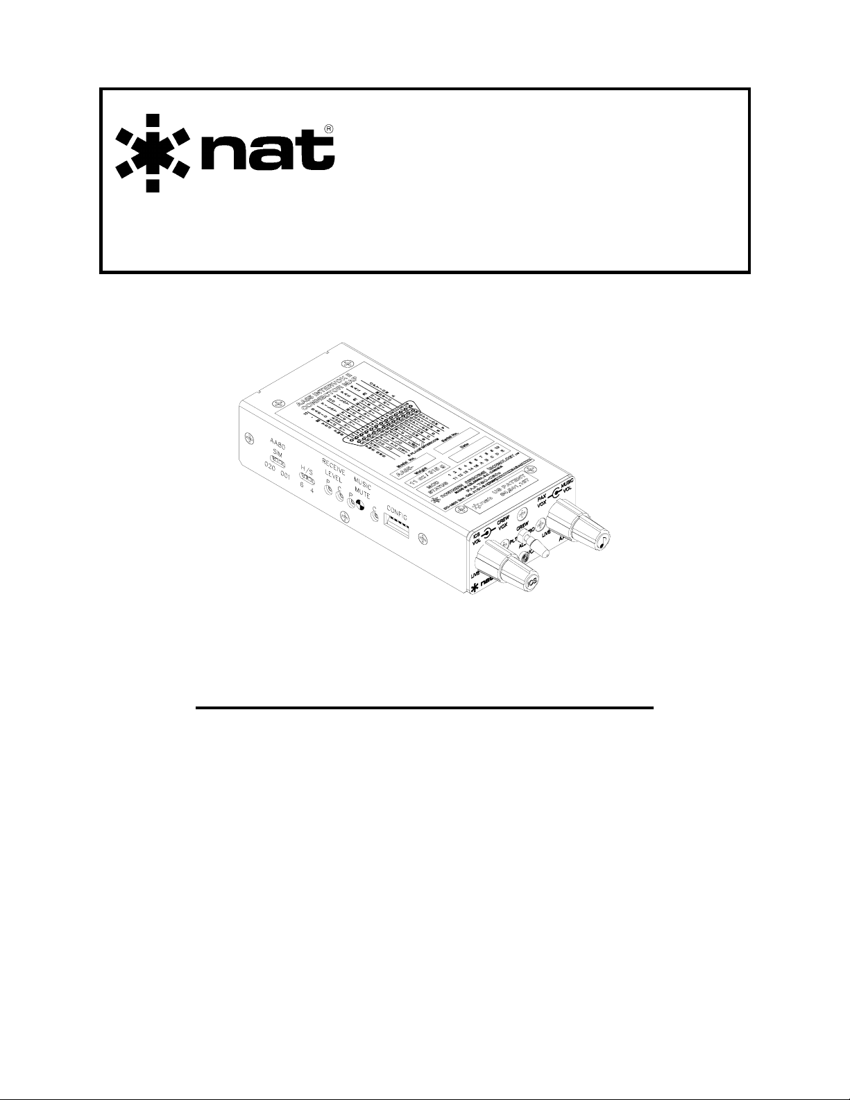
InterVOX II™ Intercom
INSTALLATION AND OPERATION MANUAL
REV 4.10 June 9, 2004
Northern Airborne Technology Ltd.
1925 Kirschner Road
Kelowna BC, Canada
V1Y 4N7
Telephone (250) 763-2232
Facsimile (250) 762-3374
Copyright 2004 by Northern Airborne Technology
CONFIDENTIAL AND PROPRIETARY TO NORTHERN AIRBORNE TECHNOLOGY LTD.
Page 2

Page 3

SM38 Rev. 4.10 AA85 InterVOX II™ Intercom Manual
Performed at factory
Performed at factory
Periodically NAT will release manual amendments. In order to maintain the most
accurate and up to date manual these amendments should be carried out immediately
upon receipt and recorded on the following amendment record.
AMENDMENT RECORD
Amendment
Number
Amendment
Date
Section(s)
Changed
Date
Entered
Entered By
1 Jan 18\ 05 2
2 Apr 11\06 2
Insert any Amendment Instruction sheets after this page.
Jan 26, 2005 Page ii
ENG-FORM: 820-0109.DOT
CONFIDENTIAL AND PROPRIETARY TO NORTHERN AIRBORNE TECHNOLOGY LTD.
Page 4

Page 5
INSTALL_OPS
MANUAL AMENDMENT
Manual: SM38_AA85 Amendment #: 2
Document #: SM38\Install_Ops\809-0002 Amendment Date: Apr 11, 2006
The purpose of this amendment is to correct the voltage/resistance checks section.
Amendment Instructions:
1
2-7 and 2-8 Rev 4.10 Amendment # 1 2-7 and 2-8 Rev 4.10 Amendment # 2
2 Update the Amendment Record sheet at the front of the manual.
3 Insert this page into the manual after the Amendment Record sheet (page ii).
Manual Amendment ends after the following amended pages
Remove Pages Replace With Pages
Amendment # 2 Apr 11, 2006 Page 1
ENG-FORM: 809-0109.DOT
CONFIDENTIAL AND PROPRIETARY TO NORTHERN AIRBORNE TECHNOLOGY LTD.
Page 6

Page 7
INSTALL_OPS
MANUAL AMENDMENT
Manual: SM38 (AA85-001) Amendment #: 1
Document # SM38\Install_Ops\809-0001 Amendment Date: Jan 18, 2005
The purpose of this amendment is to update Cable and Wiring statement, section 2.3.4,
paragraph 1.
Amendment Instructions:
1
2-3 and 2-4 Rev 4.10 2-3 and 2-4 Rev 4.10 Amendment #1
Note: Ensure that all drawings are inserted in the order shown on the latest drawing lists.
2 Update the Amendment Record sheet at the front of the manual.
3 Insert this page into the manual after the Amendment Record sheet (page ii).
Manual Amendment ends after the following amended pages
Remove Pages Replace With Pages
Amendment #1 Jan 18, 2005 Page 1
ENG-FORM: 809-0109.DOT
CONFIDENTIAL AND PROPRIETARY TO NORTHERN AIRBORNE TECHNOLOGY LTD.
Page 8

Page 9

SM38 Rev. 4.10 AA85 InterVOX II™ Intercom Manual
Table of Contents
Section Title Page
1 Description
1.1 Introduction 1-1
1.2 Purpose of Equipment 1-1
1.3 Features 1-1
1.4 Specifications 1-2
1.4.1 Electrical Specifications 1-2
1.4.2 Physical Specifications 1-2
1.4.3 Environmental Specifications 1-3
1.5 Unit Nomenclature 1-3
2 Installation
2.1 Introduction 2-1
2.2 Unpacking and Inspection 2-1
2.2.1 Warranty 2-1
2.3 Installation Procedures 2-1
2.3.1 Warnings 2-1
2.3.2 Cautions 2-2
2.3.3 Notes 2-2
2.3.4 Cabling and Wiring 2-3
2.3.5 Installation Options 2-4
2.3.6 Adjustments 2-6
2.3.7 Adjustment procedure 2-7
2.3.8 Mechanical Installation 2-8
2.3.9 Post-Installation Checks 2-8
2.4 Continued Airworthiness 2-9
2.5 Accessories Required 2-10
2.6 Installation Drawings 2-10
3 Operation
3.1 Introduction 3-1
3.2 General 3-1
3.3 Controls and Indicators 3-1
3.3.1 Mode switch 3-2
3.3.2 VOX Controls 3-2
3.3.3 Volume Controls 3-3
3.3.4 TX/ICS Indicator 3-3
3.3.5 ICS Mute Functions 3-3
3.3.6 Music Mute Functions 3-4
3.4 Intercom Adjustments 3-4
3.4.1 Receive Level 3-4
3.4.2 Music Mute 3-4
Jun 9, 2004 Page iii
ENG-FORM: 820-0109.DOT
CONFIDENTIAL AND PROPRIETARY TO NORTHERN AIRBORNE TECHNOLOGY LTD.
Page 10

Page 11

SM38 Rev. 4.10 AA85 InterVOX II™ Intercom Manual
Section 1 Description
1.1 Introduction
This manual contains information on the AA85-001 Intervox II Intercom.
Information in this section consists of purpose of equipment, features, specifications,
and unit nomenclature.
1.2 Purpose of Equipment
The AA85-001 InterVox II Intercom provides full radio and intercom capabilities for the
pilot and copilot, plus intercom and receive radio functions for up to four passengers.
The music input provides entertainment audio at all positions.
1.3 Features
The AA85-001 has been designed to be backward compatible with the AA80. This
allows simple upgrades to existing installations. The AA85-001 can be configured to
simulate any of the following AA80 InterVox units:
- AA80-001
- AA80-020
- AA80-060
- AA80-062
Stereo music source is selectable between portable cassette tape/CD players and
remote CD changers/am/fm cassette players.
Receive audio and microphone input will mute the music to an adjustable level.
Both crew and passenger receive audio controlled by trimpots.
Individual VOX detector on each of the microphone inputs and on the ICS tie line.
In Crew Isolate mode, the crew and passengers have separate headset audio with
independent music muting and the passenger's radio receive audio is muted
continuously.
Number of passenger headsets, ICS Tie Line and ICS Key Line configuration are
selected by configuration switches.
DIP switches accessible through the side of the unit control the ICS gain for multiple unit
installations.
June 9, 2004 Page 1-1
ENG-FORM: 800-0106.DOT
CONFIDENTIAL AND PROPRIETARY TO NORTHERN AIRBORNE TECHNOLOGY LTD.
Page 12

AA85 InterVOX II™ Intercom Manual SM38 Rev. 4.10
1.4 Specifications
1.4.1 Electrical Specifications
Input Power +12.4 to 30.3 Vdc at 400 mA to 1.5 A max
Input Signals
Microphone 6 inputs (2 crew and 4 Passengers),
250 mVrms @ 150 Ω.
Radio 2.5 Vrms @1 kΩ.
Music:
Portable CD/Cassette 250 mVrms to 700 mVrms @ 1kΩ
400 mVrms @ 1kΩ (Nominal)
Multi Disk CD Changer 850 mVrms to 2.4 Vrms @ 3 kΩ
1.4 Vrms @ 3 kΩ (Nominal)
Keyline Transmit capability for pilot and copilot, with
pilot priority. One ICS key for all microphones.
Output Signals
Phones 6 outputs (2 crew and 4 Passengers), 100 mW
into 600 Ω nominal (each headset)
ICS Tie Channel One input, bi-directional, 340 mVrms ±10% into 2
kΩ. Frequency response 350 Hz to 3 kHz.
Audio Frequency Response 350 - 6 kHz ± 3dB with ≤ 1% THD
Crosstalk:
Input - Input < 60 dB
Input - Output < 55 dB
Input - Mic < 1.0 mVrms
1.4.2 Physical Specifications
Height 1.3 inches (33 mm).
Length 5.8 inches (147 mm).
Width 2.6 inches (66 mm).
Weight 0.7 lb (315 g).
Mounting Through front panel; 3 X 6-32 black brass screws.
Page 1-2 June 9, 2004
ENG-FORM: 800-0106.DOT
CONFIDENTIAL AND PROPRIETARY TO NORTHERN AIRBORNE TECHNOLOGY LTD.
Page 13

SM38 Rev. 4.10 AA85 InterVOX II™ Intercom Manual
1.4.3 Environmental Specifications
Temperature:
Operating -20 C to +55 C
Survival -55 C to +85 C
Altitude 50,000 ft
Humidity 95%
Shock :
Operational 6 g
Crash Safety 15 g
Qualification:
DO-160C Env. Cat. A1/D1-BA[BMN]XXXXXXZBABAUZXXX
TSO Compliance
TSO C50c, RTCA DO-170 Class 1b
(Only applicable to units Serial # 3000 and above)
1.5 Unit Nomenclature
Model Description / Distinction
AA85-001 Selectable 4 or 6 place operation.
Music muted during ICS and radio operations.
Individual mic gating.
Two color LED.
ICS volume, Music volume and VOX Squelch controls.
Live, Keyed and VOX Intercom modes.
End of section 1
June 9, 2004 Page 1-3
ENG-FORM: 800-0106.DOT
CONFIDENTIAL AND PROPRIETARY TO NORTHERN AIRBORNE TECHNOLOGY LTD.
Page 14

Page 15

SM38 Rev. 4.10 AA85 InterVOX II™ Intercom Manual
Section 2 Installation
2.1 Introduction
Information in this section consists of: unpacking and inspection procedures, installation
procedures, post-installation checks, and installation drawings.
Note: To meet TSO compliance for serial numbers 3000 and above, follow
interconnect drawing Revision 2.00 or higher. Ensure the installation is
completed using the metal ‘hood’ to enclose the AA85 connector.
2.2 Unpacking and Inspection
Unpack the equipment carefully and locate the warranty card. Inspect the unit visually
for damage due to shipping and report all such claims immediately to the carrier
involved. Note that each unit should have the following:
- AA85-001 InterVOX II™ Intercom
- Install Kit (with metal ‘hood’)
- Warranty Card
- Operators Manual
- Release certification
Verify that all items are present before proceeding and report any shortage immediately
to your supplier.
2.2.1 Warranty
Complete the warranty card information and send it to NAT when the installation is
complete. If you fail to complete the warranty card, the warranty will be activated on
date of shipment from NAT.
Note: An appropriately rated facility, e.g. Certified Aircraft Repair Station, must install this
equipment in accordance with applicable regulations. NAT Ltd’s warranty is not
valid unless the equipment is installed by an authorized NAT Dealer. Failure to
follow any of the installation instructions, or installation by a non-certified individual
or agency will void the warranty, and may result in a non-airworthy installation.
2.3 Installation Procedures
2.3.1 Warnings
Do not bundle any lines from this unit with transmitter coax lines. Do not bundle any
audio or DC power lines from this unit with 400 Hz synchro wiring or AC power lines. Do
not position this unit or wiring from this unit next to any device with a strong alternating
magnetic field such as an inverter, or significant audio interference will result.
June 9, 2004 Page 2-1
ENG-FORM: 805-0106.DOT
CONFIDENTIAL AND PROPRIETARY TO NORTHERN AIRBORNE TECHNOLOGY LTD.
Page 16
AA85 InterVOX II™ Intercom Manual SM38 Rev. 4.10
2.3.2 Cautions
In all installations, use shielded cable exactly as shown and ground as indicated. Significant
ground loop and noise problems may result from not following these guidelines. Ensure
chassis is grounded to provide proper shield terminations.
Ensure microphone and headphone jacks are isolated from the airframe ground.
Use caution when routing microphone and ICS Tie Line wiring, as they are low level
signals prone to coupling from other sources.
Do not take a ground from the instrument panel or similar location that shares a ground
return with a turn and bank, horizon or other motor driven instrument. This may cause
the unit to pick up the sound of the motor as ground loop interference.
2.3.3 Notes
The AA85-001 has been manufactured and delivered in both TSO'd (serial # 3000 and
above) and non-TSO'd versions (below serial # 3000). There are critical differences in
the interconnect between the two types, which must be observed to ensure compliance
with the TSO requirements.
TSO'd units are shipped from the factory with 'jack posts' installed at the chassis connector.
The install kit supplied with the AA85 contains a metal 'hood' that must be used on the
airframe connector to ensure compliance with the stated TSO qualification requirements.
Earlier generations of the AA85 (non TSO'd, below s/n 3000) used V5, 'spring lock'
mounting hardware for the chassis connector, with jack posts as an alternative.
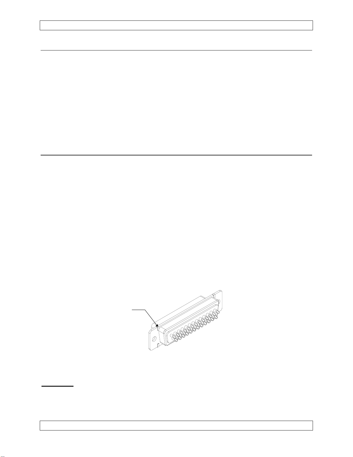
If installing this unit into an existing aircraft harness, ensure that the harness connector
does not have the ‘tabs’ shown in figure 1. If the harness connector does have ‘tabs’,
replace the existing harness connector with the one included in the install kit.
Tab
Harness Connector
Figure 1
Important
: Although it is possible to install and operate a new TSO'd unit in an
older installation, the system will not be compliant with the stated
TSO requirements due to the differences in the interconnect.
Page 2-2 June 9, 2004
ENG-FORM: 805-0106.DOT
CONFIDENTIAL AND PROPRIETARY TO NORTHERN AIRBORNE TECHNOLOGY LTD.
Page 17
SM38 Rev. 4.10 AA85 InterVOX II™ Intercom Manual
2.3.4 Cabling and Wiring
All unshielded wire shall be selected in accordance with AC43.13-1B Change 1,
Paragraphs 11-76 through 11-78. Wire types should be to MIL-W-22759 as specified in
AC43.13-1B Change 1, Paragraphs 11-85, 11-86, and listed in Table 11-11. For
shielded wire applications, use Tefzel MIL-C-27500 shielded wire with solder sleeves
(for shield terminations) to make the most compact and easily terminated interconnect.
Follow the wiring diagrams in Section 2.6 as required.
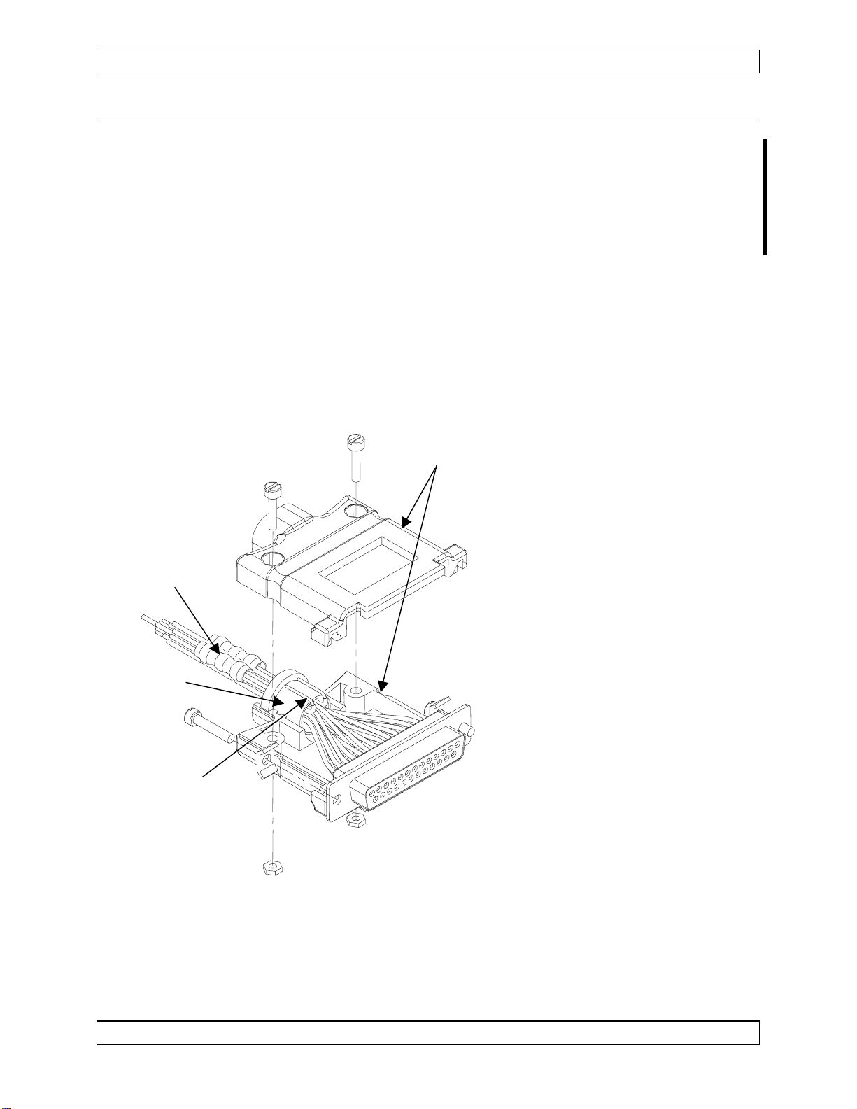
Allow 3 inches from the end of the wire to the shield termination to allow the hood to be
easily installed. Note that the hood is a ‘clamshell’ hood, and is installed after the wiring
is complete.
Note: When replacing a previous AA80 series Intercom with an AA85 serial # 3000 and
above, harness changes are necessary to ensure compliance of the AA85 with
the approved TSO configuration. Refer to Section 2.3.3 for further details.
Group the mic audio shields
Metal Hood
separately from all other audio
shields.
Utilizing Raychem solder sleeves,
create up to 6 shield pigtails in the
Raychem
Solder Sleeves
wiring harness, as shown in the
Interconnect Diagram
(AA85\001\403-x, Rev 2.00 or
higher). Each pigtail should be no
more than 3.0” long.
Bring the pigtails through the
Rubber
Grommet
rubber grommet and strip off 0.5”
of insulation.
Bend the stripped portion back
onto the grommet as shown and
Stripped
Pigtail
sandwich the pigtails between the
connector hood and the grommet.
Note: The hood is a ‘two-piece’
unit, and is assembled after
the wiring is complete.
All wiring should be at least 24 AWG, except power and ground lines, which should be
at least 20 AWG. Ensure that all ground connections are clean and well secured.
To prevent system failure or inadequate equipment protection, supply power from a
dedicated 2.0 A circuit breaker.
Jun 9, 2004 Page 2-3
ENG-FORM: 805-0106.DOT Amendment #1 Jan 18, 2005
CONFIDENTIAL AND PROPRIETARY TO NORTHERN AIRBORNE TECHNOLOGY LTD.
Page 18

AA85 InterVOX II™ Intercom Manual SM38 Rev. 4.10
2.3.5 Installation Options
The AA85-001 can be configured to simulate any of the following AA80 InterVOX™
units:
AA80-001
Single unit installation (no ICS tie line) providing radio and intercom capabilities for
the pilot and copilot, plus intercom and radio receive functions for two passengers.
The unit provides left and right stereo music inputs (note stereo input mixes
internally and outputs as mono). ICS PTT functions are not available.
AA80-020
Multiple unit installation (includes ICS tie line) providing radio and intercom capabilities
for the pilot and copilot, plus intercom and radio receive functions for two passengers.
The unit provides only one mono music input. ICS PTT functions are available.
AA80-060
Single unit installation (no ICS tie line) providing transmit and intercom capabilities
for the pilot and copilot, plus intercom and radio receive functions for four
passengers. The unit provides left and right stereo music inputs (note stereo input
mixes internally and outputs as mono). ICS PTT functions are not available.
AA80-062
Multiple unit installation (includes ICS tie line) providing radio and intercom capabilities
for the pilot and copilot, plus intercom and radio receive functions for four passengers.
The unit provides only one mono music input. ICS PTT functions are available.
The unit ships from the factory with the switches set to simulate an AA80-001,
with a portable cassette/CD player music input and the crew music unmuted.
The switches that determine the configuration installed are AA80 SIM, H/S and CONFIG
switches 1, 2 and 5, accessible through the left-hand side of the unit. Refer to figure 2
to determine the correct switch settings.
Page 2-4 Jun 9, 2004
ENG-FORM: 805-0106.DOT Amendment #1 Jan 18, 2005
CONFIDENTIAL AND PROPRIETARY TO NORTHERN AIRBORNE TECHNOLOGY LTD.
Page 19

SM38 Rev. 4.10 AA85 InterVOX II™ Intercom Manual
Switch 2 - up
6
Switch 1 - down
Configuration Switches - figure 2
AA80 SIM
Set to 001 to simulate an AA80-001 or AA80-060.
Set to 020 to simulate an AA80-020 or AA80-062.
CONFIG 1 - ICS Gain (1 NAT load)
Set to down to simulate an AA80-020 or AA80-062 with one other NAT unit loading
the ICS tie line.
CONFIG 2 - ICS Gain (2 NAT loads)
Set to down when there is more than one NAT load on the ICS tie line. Note:
CONFIG 1 switch remains down in this configuration.
CONFIG 5 - PAX ICS TIE Load Balance
Use this switch in conjunction with any ICS tie line load. The switch is down when
the ICS tie line is used.
June 9, 2004 Page 2-5
ENG-FORM: 805-0106.DOT
CONFIDENTIAL AND PROPRIETARY TO NORTHERN AIRBORNE TECHNOLOGY LTD.
Page 20

AA85 InterVOX II™ Intercom Manual SM38 Rev. 4.10
In addition, there are 2 user selectable options available through CONFIG switches 3
and 4. They are:
CONFIG 3 - Portable Tape/CD or CD Changer
This allows the user to input music from either a portable cassette/CD player (phone
output) or CD changers/am/fm cassette players (line output). Select this switch to
the down position to accept music from the ‘phone’ output of a portable cassette/CD
player. Select this switch to the up position to accept music from the ‘line’ output of
a CD changer/am/fm cassette player. When using a portable cassette/CD player,
NAT recommends that the phone output should be used for interface to increase
tone control and volume. (The ‘line out’ output lacks volume and tone control.) Set
the volume about half way.
CAUTION
Certain aircraft installations may use a car type, am/fm cassette or CD
player. For best performance and simplicity of installation, use the ‘line’
output from the stereo unit and set the CONFIG 3 switch to the up
position. If it is necessary to use the ‘speaker’ outputs from the stereo
unit, a floating ground adapter and input attenuation network (resistors)
may be required to provide the correct system interconnect and to prevent
damage to the music input(s) of the AA85.
CONFIG 4 - Crew Music Mute
This feature allows the crew to have the music muted when operating in the Crew
mode. Select this switch to the down position so the crew will hear the music at the
muted level set by the MUSIC MUTE C trimpot. See the Operation section 3.3.6 for
more information. Select this switch to the up position so the crew will hear the
music at the music volume level.
Note: CONFIG switch 6 is a spare and has no connection.
2.3.6 Adjustments
The unit ships from the factory with all internal adjustments set to the normal test levels.
Once installed in the aircraft, it may be desirable to change some of these settings to
best suit the local operating environment. The internal adjustments are located along
the left side of the unit and are as follows:
CAUTION
Before performing the following adjustments ensure the aircraft radio’s
volume control is set to produce 2.5 Vrms ±10 % at the input to the AA85,
or the mute functions may not operate correctly.
Page 2-6 June 9, 2004
ENG-FORM: 805-0106.DOT
CONFIDENTIAL AND PROPRIETARY TO NORTHERN AIRBORNE TECHNOLOGY LTD.
Page 21

SM38 Rev. 4.10 AA85 InterVOX II™ Intercom Manual
2.3.6.1 RECEIVE LEVEL
The minimum volume level of receive audio is controlled separately for the passengers
and crew. The crew setting can be adjusted by potentiometer RECEIVE LEVEL C. The
crew setting can not be fully muted. The passenger setting can be adjusted by
potentiometer RECEIVE LEVEL P. The passenger level can be fully muted, if desired.
The cw rotation of either of these controls will increase receive audio volume level.
Adjust the crew setting in both CREW and PLT ISO modes to ensure satisfactory levels
in both modes.
Note: If the radio TX sidetone seems too loud, it may be necessary to ‘balance’ the
radio RX audio, TX sidetone, and AA85 Receive level ‘C’.
2.3.6.2 MUSIC MUTE
The music mute level sets the volume that the music will drop to during a music mute
condition. There are separate level adjustments for the crew and passengers. The
crew setting can be adjusted by potentiometer MUSIC MUTE C. The passenger setting
can be adjusted by potentiometer MUSIC MUTE P.
To set the mute level, set the AA85 to ALL mode and the associated VOX knob to live
(fully ccw). Inject music and adjust the associated mute trim pot to adjust the amount of
muting (cw to increase and ccw to decrease). The fully ccw position gives a minimum
muting of 25%. At 12 o’clock, the muting level is 50% and at fully cw the muting level is
100%.
2.3.7 Adjustment procedure
2.3.7.1 To set the configuration desired, see the applicable drawings as listed in
section 2.5.
2.3.7.2 Inject radio audio as adjusted in section 2.3.6, inject music (if being used
in the installation) and then listen to a crew headset. Adjust RECEIVE
LEVEL C until the desired level is reached. The music should be muted.
2.3.7.3 Listen to a PAX headset and adjust RECEIVE LEVEL P until the desired
level is reached.
2.3.7.4 Discontinue the radio injection.
2.3.7.5 Put on a crew headset. Adjust MUSIC MUTE C until the desired level is
reached, while speaking into the mic.
2.3.7.6 Put on a PAX headset. Adjust MUSIC MUTE P until the desired level is
reached, while speaking into the mic.
Jun 9, 2004 Page 2-7
ENG-FORM: 805-0106.DOT Amendment #2 Apr 11, 2006
CONFIDENTIAL AND PROPRIETARY TO NORTHERN AIRBORNE TECHNOLOGY LTD.
Page 22

AA85 InterVOX II™ Intercom Manual SM38 Rev. 4.10
2.3.8 Mechanical Installation
The AA85 can be installed in any attitude, using the AA85-IKC Installation kit (refer to
Section 1.5 for details).
For proper installation, refer to the Mounting Diagram (AA85\001\920-0) and the
following steps:
a) Before proceeding to install the AA85-001 into the aircraft, secure the black metal
faceplate to the AA85-001 with one mounting screw (countersink holes facing out).
b) Remove the desired label from the sheet provided and using minimum pressure
align the label on the black faceplate. When the alignment is correct remove the
faceplate from the unit.
c) Lay the faceplate on a flat surface and press label firmly in place ensuring there
are no air bubbles.
d) Referencing the drill template, drill required mounting holes in the aircraft panel
and insert the AA85-001 from behind the panel.
e) Attach the black metal faceplate (with label attached) from the front with the
countersunk holes facing out. Secure with the mounting screws provided. Note:
Ensure that the AA85-001 and faceplate tightly sandwich the aircraft panel.
f) Rotate the shaft of the CREW VOX potentiometer fully ccw. Align the white
marker on the outer concentric knob (part of 40-21-ICS3) to the LIVE position on
the faceplate label. Using a 0.05” Allen key, tighten the knob onto the
potentiometer shaft.
g) Using a 0.05” Allen key, loosely attach the inner concentric knob (part of 40-21-
ICS3) onto the ICS VOL potentiometer shaft. Rotate the shaft of the ICS VOL
potentiometer fully ccw. Using an Allen key loosen the knob on the
potentiometer shaft and align the white marker on the inner concentric knob (part
of 40-21-ICS3) to the LIVE position on the faceplate label. Using an Allen key
tighten the knob onto the potentiometer shaft.
h) Repeat steps f and g for the MUSIC VOL and PAX VOX potentiometer shafts
and knob set 40-21-MUS3.
2.3.9 Post-Installation Checks
2.3.9.1 Voltage/resistance checks
Do not attach the AA85-001 until the following conditions are met.
Check the following:
a) Check P101, pin <1> for +12 to 30 Vdc relative to ground.
b) Check P101, pin <14> for continuity to ground (less than 0.5 Ω).
Page 2-8 Jun 9, 2004
ENG-FORM: 805-0106.DOT Amendment #2 Apr 11, 2006
CONFIDENTIAL AND PROPRIETARY TO NORTHERN AIRBORNE TECHNOLOGY LTD.
Page 23

SM38 Rev. 4.10 AA85 InterVOX II™ Intercom Manual
2.3.9.2 Power On checks
Install the AA85-001 and power up the ship’s systems. Verify normal operation of all
functions. Refer to Section 3 for specific operation details.
a) Begin with only the pilot's headset installed, no hand mic. Check for correct radio
operation both receive and transmit. Check yoke (or cyclic) switch action.
b) If there is a music source in the system turn it on and verify that music is heard in
all modes except PLT ISO. Check for proper mute operation.
Note: Unusual buzzes, hums or other background audio are symptomatic of
multiple grounds, or noisy external systems such as blowers or pumps
sharing wiring with the audio system. Failure to key or correctly modulate
a transmitter is often the result of forgetting to connect all required
grounds to the radio or external audio system.
c) Plug in the copilot's headset. Check for correct ICS operation. Check pilot's
transmit priority. Check yoke switch functions.
d) Plug in the hand mic, and test for correct operation in all modes. It must activate
the transmitter(s) in all cases.
e) Plug in any remaining headsets, and check for correct ICS operation.
Note: Incorrect jack wiring is a common fault for rear passenger stations, and
may cause a wide range of problems.
f) To verify proper operation, all functions and levels should be checked in-flight.
Upon satisfactory completion of all performance checks, make the required log
entries and complete the necessary Regulatory Agency paperwork before
releasing the aircraft for service.
2.4 Continued Airworthiness
Maintenance of the AA85-001 InterVOX II™ Intercom is ‘on condition’ only. Periodic
maintenance of this product is not required.
June 9, 2004 Page 2-9
ENG-FORM: 805-0106.DOT
CONFIDENTIAL AND PROPRIETARY TO NORTHERN AIRBORNE TECHNOLOGY LTD.
Page 24

AA85 InterVOX II™ Intercom Manual SM38 Rev. 4.10
2.5 Accessories Required
An installation kit is required to complete the installation. The AA85-IKC (crimp) is
supplied with the unit, and consists of:
AA85-IKC (crimp)
Quantity Description NAT Part #
1 D-min 25 pin Socket housing 20-21-025
25 MS Crimp Socket 20-26-901
1 Hood, D-min, Metal 20-28-028
1 Hole Overlay Drill Template 43-10-085
1 Front Label (Lexan) 43-41-085
1 Rectangular Black Faceplate (Blank) 50-04-851
1 Fluted Knob set (Music) 40-21-MUS3
1 Fluted Knob set (ICS) 40-21-ICS3
3 CSK Black 6-32 Mounting Screws 25-11-028
2.6 Installation Drawings
DRAWING REV. DESCRIPTION TYPE Serial #’s
AA85\001\403-0 1.10 InterVOX II Intercom (AA80-001) Interconnect 1059 - 2999
AA85\001\403-1 1.10 InterVOX II Intercom (AA80-020) Interconnect 1059 - 2999
AA85\001\403-2 1.10 InterVOX II Intercom (AA80-060) Interconnect 1059 - 2999
AA85\001\403-3 1.10 InterVOX II Intercom (AA80-062) Interconnect 1059 - 2999
AA85\001\403-0 2.00 InterVOX II Intercom (AA80-001) Interconnect 3000 and up
AA85\001\403-1 2.00 InterVOX II Intercom (AA80-020) Interconnect 3000 and up
AA85\001\403-2 2.00 InterVOX II Intercom (AA80-060) Interconnect 3000 and up
AA85\001\403-3 2.00 InterVOX II Intercom (AA80-062) Interconnect 3000 and up
AA85\001\405-0 1.01 InterVOX II Intercom Connector Map 1059 and up
AA85\001\521-0 1.00 InterVOX II Intercom Environmental Qualification Form 3000 and up
AA85\905-0 1.00
AA85\920-0 1.00
AA85\922-0 1.01
AA85\922-0 1.10
InterVOX II Intercom
InterVOX II Intercom
InterVOX II Intercom
InterVOX II Intercom
Faceplate 1059 and up
Mounting 1059 and up
Mech. Installation 1059 - 2999
Mech. Installation 3000 and up
Section 2 ends after these Drawings
Page 2-10 June 9, 2004
ENG-FORM: 805-0106.DOT
CONFIDENTIAL AND PROPRIETARY TO NORTHERN AIRBORNE TECHNOLOGY LTD.
Page 25

Page 26

Page 27

Page 28

Page 29

Confidential and Proprietary to NAT
Page 30

Page 31

Page 32

Page 33

Page 34

Page 35

Page 36

Page 37

Page 38

Page 39

Page 40

Page 41

Confidential and Proprietary to NAT
Page 42

Page 43

Page 44

Page 45

Page 46

Page 47

Confidential and Proprietary to NAT
Page 48

Page 49

Confidential and Proprietary to NAT
Page 50

Page 51

Confidential and Proprietary to NAT
Page 52

Page 53

Page 54

Page 55

SM38 Rev. 4.10 AA85 InterVOX II™ Intercom Manual
Section 3 Operation
3.1 Introduction
Information in this section consists of the functional and operational procedures for the
AA85-001 InterVOX II™ Intercom.
3.2 General
The AA85-001 provides full radio and intercom capabilities for the pilot and copilot, plus
intercom and radio receive functions for up to four passengers. Music is available at all
positions.
The crew and passengers have individual control over VOX through CREW VOX and
PAX VOX respectively.
One volume control sets the ICS volume in all six headsets. One volume control sets
the music volume in all six headsets.
The AA85-001 can be configured to simulate any of the following AA80 InterVox units:
- AA80-001
- AA80-020
- AA80-060
- AA80-062
3.3 Controls and Indicators
Dual Control:
ICS Volume(inner)
and Crew VOX (outer)
Mode Switch
TX/ICS Indicator
Dual Control:
Music Volume (inner)
and PAX VOX (outer)
Jun 9, 2004 Page 3-1
ENG-FORM: 806-0106.DOT
CONFIDENTIAL AND PROPRIETARY TO NORTHERN AIRBORNE TECHNOLOGY LTD.
Page 56

AA85 InterVOX II™ Intercom Manual SM38 Rev. 4.10
3.3.1 Mode switch
This red, three position toggle switch is used for selecting the intercom mode.
3.3.1.1 ALL
The ALL position connects all headsets and the ICS tie line. All headsets will hear
aircraft radio audio and music.
3.3.1.2 CREW
The CREW position separates the headset audio of the crew and passengers, and
isolates the intercom audio between the crew and passengers. Only the crew will hear
radio audio. Passengers and crew will still hear music. The ICS tie line connects with
the crew intercom only.
3.3.1.3 PLT ISO
The PLT ISO position isolates the pilot from all intercom and music functions. The
aircraft radio connects to the pilot’s mic and headset directly. The copilot and
passengers will not be able to hear the aircraft radio audio, but will retain intercom and
music functions and their connection to the ICS tie line.
CAUTION
In PLT ISO, the copilot position cannot transmit mic audio but
can still key the radio. This will cause the pilot’s microphone
to be live. If the copilot keys the radio, the music will mute
and the AA85 TX/ICS indicator will illuminate green.
3.3.2 VOX Controls
The AA85-001 has two independent VOX controls. The outer knob of the right hand dual
control is PAX VOX and controls the VOX level for all passengers. The outer knob of the
left hand dual control is CREW VOX and controls the VOX level for the pilot and copilot.
The VOX controls set the level of audio required to activate the microphones. When
either of the VOX controls is set fully ccw (LIVE), the associated microphone(s) will be
active at all times (Hot Mic). Ground operations, where little background noise is
present, commonly use this setting.
As the operator rotates the control in a cw direction the amount of audio required to
activate the microphone(s) increases. Noisy conditions, where ‘pilot fatigue’ may result,
commonly use this setting.
In system configurations that provide ICS PTT operation, the ICS PTT input will override
the VOX setting.
Page 3-2 Jun 9, 2004
ENG-FORM: 806-0106.DOT
CONFIDENTIAL AND PROPRIETARY TO NORTHERN AIRBORNE TECHNOLOGY LTD.
Page 57

SM38 Rev. 4.10 AA85 InterVOX II™ Intercom Manual
3.3.3 Volume Controls
3.3.3.1 ICS Volume Control
The inner knob of the left hand dual control is ICS VOL and controls the intercom
volume for all headsets. An internal trimpot sets the minimum level. With ICS VOL set
fully ccw intercom volume will be at a minimum. As the operator rotates the control cw,
intercom volume will increase.
3.3.3.2 Music Volume Control
The inner knob of the right hand dual control is MUSIC VOL and controls the music
volume for all headsets. With MUSIC VOL fully ccw music volume will be at a minimum.
As the operator rotates the control cw, music volume will increase.
CAUTION
The AA85 has no front panel radio volume control. Take
care when adjusting aircraft radios as low radio volume may
affect the AA85 mute functions.
3.3.4 TX/ICS Indicator
The TX/ICS indicator is a dual color LED that will illuminate green during radio transmit
operations and amber during ICS operations.
3.3.5 ICS Mute Functions
3.3.5.1 ALL Mode
In ALL mode, intercom audio will mute at all positions whenever the pilot or copilot
‘Keys’ the radio.
3.3.5.2 Crew Mode
In CREW mode, intercom audio will mute at both crew positions whenever the pilot or
copilot ‘Keys’ the radio. Passenger ICS is not affected.
3.3.5.3 PLT ISO
In PLT ISO mode, copilot and passenger intercom audio will not mute when the pilot
‘Keys’ the radio, but will mute when the copilot ‘Keys’ the radio. The pilot has no
connection to any intercom or music functions, and therefore requires no mute.
Jun 9, 2004 Page 3-3
ENG-FORM: 806-0106.DOT
CONFIDENTIAL AND PROPRIETARY TO NORTHERN AIRBORNE TECHNOLOGY LTD.
Page 58

AA85 InterVOX II™ Intercom Manual SM38 Rev. 4.10
3.3.6 Music Mute Functions
3.3.6.1 ALL Mode
In ALL mode, music audio will mute at all positions when any crew member ‘Keys’ the
radio. All positions will also mute whenever aircraft radio audio is present or if the ICS
is active.
3.3.6.2 Crew Mode
In CREW mode, music audio will mute at both crew positions whenever the pilot or
copilot ‘Keys’ the radio; when aircraft radio audio is present; if the crew ICS is active; or
if the ICS Tie Line is active. Passenger music audio will mute only when the passenger
ICS is active.
If Crew Music Mute has been configured at installation, the music for the crew is muted
automatically when CREW mode is selected.
3.3.6.3 PLT ISO
In PLT ISO mode, copilot and passenger music audio will not mute when the pilot ‘Keys’
the radio or when aircraft radio audio is present. Passenger music audio will not mute if
the copilot ‘Keys’ the radio, but copilot music audio will mute. Both copilot and
passenger music audio will mute during all ICS operations.
3.4 Intercom Adjustments
These adjustments are not accessible with the unit installed. They should only be
carried out at an approved dealer, BY FULLY QUALIFIED PERSONNEL.
3.4.1 Receive Level
Separate trimpots control the minimum volume level of receive audio for the passengers
and crew. The crew setting cannot be fully muted. The passenger level can be fully
muted if desired.
3.4.2 Music Mute
The music mute level sets the volume that the music will drop to during a music mute
condition. There are separate levels for the crew and passengers.
End of section 3
Page 3-4 Jun 9, 2004
ENG-FORM: 806-0106.DOT
CONFIDENTIAL AND PROPRIETARY TO NORTHERN AIRBORNE TECHNOLOGY LTD.
Page 59

 Loading...