

Page 1
SM10
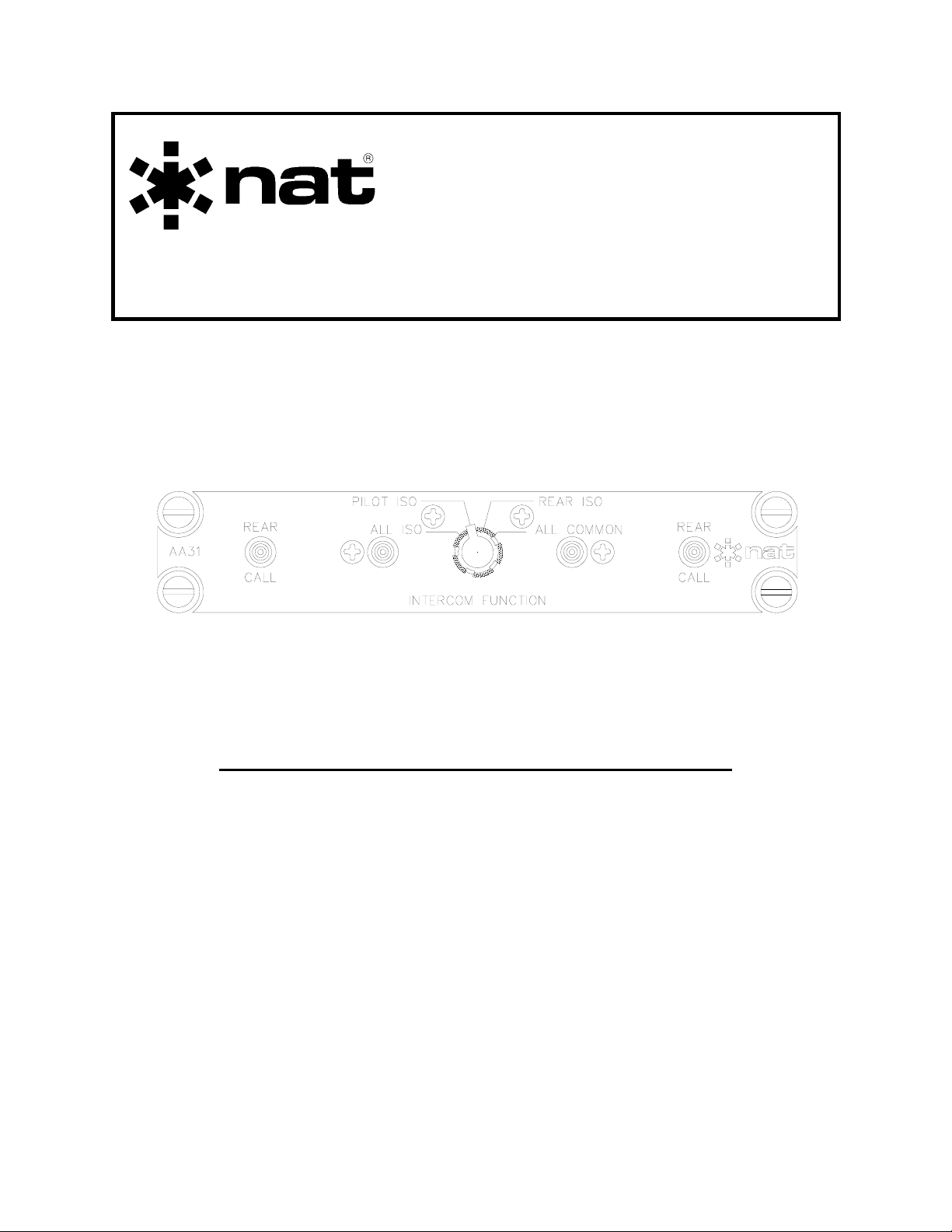
AA31
ICS Mode Controller
INSTALLATION AND OPERATION MANUAL
REV 4.10 February 4, 2005
Northern Airborne Technology Ltd.
1925 Kirschner Road
Kelowna, BC, Canada.
V1Y 4N7
Telephone (250) 763-2232
Facsimile (250) 762-3374
Copyright 2005 by Northern Airborne Technology
CONFIDENTIAL AND PROPRIETARY TO NORTHERN AIRBORNE TECHNOLOGY LTD.
Page 2

Page 3

SM10 Rev. 4.10 AA31 ICS Mode Controller Manual
Periodically NAT will release manual amendments. In order to maintain the most
accurate and up to date manual these amendments should be carried out immediately
upon receipt and recorded on the following amendment record.
AMENDMENT RECORD
Amendment
Number
Amendment
Date
Section(s)
Changed
Date
Entered
Entered By
Insert any Amendment Instruction sheets after this page.
Feb 4, 2005 Page ii
ENG-FORM: 820-0110.DOT
CONFIDENTIAL AND PROPRIETARY TO NORTHERN AIRBORNE TECHNOLOGY LTD.
Page 4

Page 5

SM10 Rev. 4.10 AA31 ICS Mode Controller Manual
Table of Contents
Section Title Page
1 Description
1.1 Introduction 1-1
1.2 Purpose of Equipment 1-1
1.3 Features 1-1
1.4 Specifications 1-2
1.4.1 Electrical Specifications 1-2
1.4.2 Physical Specifications 1-2
1.4.3 Environmental Specifications 1-3
1.5 Unit Nomenclature 1-3
2 Installation
2.1 Introduction 2-1
2.2 Unpacking and Inspection 2-1
2.2.1 Warranty 2-1
2.3 Installation Procedures 2-1
2.3.1 Warnings 2-1
2.3.2 Cautions 2-2
2.3.3 Cabling and Wiring 2-2
2.3.4 Notes 2-2
2.3.5 External Switches and Lamps 2-2
2.3.6 Post-Installation Checks 2-3
2.4 Continued Airworthiness 2-3
2.5 Accessories Required But Not Supplied 2-4
2.6 Installation Drawings 2-4
3 Operation
3.1 Introduction 3-1
3.2 General 3-1
3.3 Operation Specifics 3-1
3.3.1 Intercom Function Selector 3-1
3.3.2 Annunciators 3-2
Feb 4, 2005 Page iii
ENG-FORM: 820-0110.DOT
CONFIDENTIAL AND PROPRIETARY TO NORTHERN AIRBORNE TECHNOLOGY LTD.
Page 6

Page 7

SM10 Rev. 4.10 AA31 ICS Mode Controller Manual
Section 1 Description
1.1 Introduction
This manual contains information on the AA31-001 and AA31-002 ICS Mode
Controllers. All derivative products will be covered by manual supplements, which can
be obtained from NAT as required.
Information in this section consists of purpose of equipment, features and specifications.
1.2 Purpose of Equipment
The AA31 ICS Mode Controller provides a convenient, centralized method of organizing
the aircraft audio system into multiple intercom circuits for independent or common
operation. This function is especially valuable for EMS and law enforcement
applications, where several independent operations occur within the aircraft that often
require isolation from each other, while retaining the ability to share common
communication.
The AA31 can provide ICS switching for three or four NAT Audio Controllers, or other
NAT products incorporating an ICS TIE LINE. The AA31 also has provisions for driving
external annunciators and interfacing for ICS Calling.
1.3 Features
Front panel annunciators provide positive indication of the ICS mode selection. The
LED on the right of the ICS Function Knob lights green to indicate ICS Function is ALL
COMMON. The LED on the left of the ICS Function Knob lights amber to indicate that
any of the ICS functions is in the ISO (isolated) position.
The AA31 has four annunciator outputs, one output for each ICS Function. The outputs
on the AA31-002 can drive the Isolated Warning inputs on a NAT Audio Controller. The
outputs on the AA31-001 and AA31-002 can drive external lamps.
The AA31 provides load matching so that the ICS Levels will not change as the ICS
Function is changed. When the AA31 isolates an Audio Controller’s ICS Tie Line, it
connects a resistor, equal to the load of the ICS Tie Line, in place of the isolated Audio
Controller.
The REAR CALL annunciators illuminate when a rear call signal is activated.
ICS Function switching is a passive circuit, so it will continue to operate with no power
to the AA31. The annunciators and outputs will fail without power.
Feb 4, 2005 Page 1-1
ENG-FORM: 800-0108.DOT
CONFIDENTIAL AND PROPRIETARY TO NORTHERN AIRBORNE TECHNOLOGY LTD.
Page 8

AA31 ICS Mode Controller Manual SM10 Rev. 4.10
1.4 Specifications
1.4.1 Electrical Specifications
Input power: +28 Vdc
Power Requirements:
Nominal 155 mA max @ +27.5 Vdc
Lighting 80 mA max @ +27.5 Vdc
Annunciators:
REAR CALL (left) Amber (dimming)
REAR CALL (right) Amber (dimming)
ISO Amber (dimming)
COMMON Green (dimming)
Input Signals:
Quantity 4 ICS Tie Lines
2 Rear Call Lines
Circuitry Type Tie Lines are single ended
Output Signals:
Quantity 4 ICS Tie Lines,
2 Rear Call Lines,
4 Mode Annunciator Lines
Circuitry Type Tie Lines are single ended.
ICS Function Outputs (4) ALL ISO, REAR ISO, PILOT ISO, ALL COMMON.
AA31-001 Source 100 mA Max
AA31-002 Open Collector Output Sink 100 mA Max
1.4.2 Physical Specifications
Height 1.13" (28.7 mm)
Depth 2.82" (71.61 mm) behind panel
Width 4.90 (124.5 mm) behind panel
5.75" (146.1 mm) in front of panel
Weight 0.50 lbs. (225 g)
Mounting Panel mount Dzus rail (4 fasteners)
Faceplate Engraved acrylic edge lit panel.
Connectors Male 25-pin D-sub with jack screw fasteners
Material/Finish Chassis & cover are 5032-H32 brushed
aluminum with chromate conversion finish
Page 1-2 Feb 4, 2005
ENG-FORM: 800-0108.DOT
CONFIDENTIAL AND PROPRIETARY TO NORTHERN AIRBORNE TECHNOLOGY LTD.
Page 9

SM10 Rev. 4.10 AA31 ICS Mode Controller Manual
1.4.3 Environmental Specifications
Temperature: Normal -40° C to +55° C
Survival -55° C to +85° C.
Altitude +25,000 ft. (7,620 m).
Humidity 95 % for 48 hrs.
Shock 6 g for 11 ms.
Qualification
DO-160C Env. Cat. B4-BA[MN]XXXXXXXXXXXXXXXX
1.5 Unit Nomenclature
Other variants are available; please contact NAT for further information.
AA31-001 Mode selector for organizing multiple ICS circuits
Visual LED annunciation of mode status
External annunciation – 100 mA max @ 28 Vdc
Two rear call annunciators with separate circuits
28 Vdc backlighting
Provides voltage for external annunciation
AA31-002 Mode selector for organizing multiple ICS circuits
Visual LED annunciation of mode status
External annunciation – 100 mA max @ 28 Vdc
Two rear call annunciators with separate circuits
28 Vdc backlighting
Provides switched grounds for external annunciation
End of section 1
Feb 4, 2005 Page 1-3
ENG-FORM: 800-0108.DOT
CONFIDENTIAL AND PROPRIETARY TO NORTHERN AIRBORNE TECHNOLOGY LTD.
Page 10

Page 11

SM10 Rev. 4.10 AA31 ICS Mode Controller Manual
Section 2 Installation
2.1 Introduction
Information in this section consists of: unpacking and inspection procedures, installation
procedures, post-installation checks, and installation drawings.
2.2 Unpacking and Inspection
Unpack the equipment carefully and locate the warranty card. Inspect the unit visually
for damage due to shipping and report all such claims immediately to the carrier
involved. Note that each unit should have the following:
- AA31 ICS Mode Controller
- Warranty Card
- Operator’s Manual
- Release certification
Verify that all items are present before proceeding and report any shortage immediately
to your supplier.
2.2.1 Warranty
Complete the warranty card information and send it to NAT when the installation is
complete. If you fail to complete the warranty card, the warranty will be activated on
date of shipment from NAT.
Note: An appropriately rated facility, e.g. Certified Aircraft Repair Station, must install
this equipment in accordance with applicable regulations. NAT Ltd’s warranty is
not valid unless the equipment is installed by an authorized NAT Dealer. Failure
to follow any of the installation instructions, or installation by a non-certified
individual or agency will void the warranty, and may result in a non-airworthy
installation.
2.3 Installation Procedures
2.3.1 Warnings
Do not bundle any lines from this unit with transmitter coax lines. Do not bundle any
logic, audio, or DC power lines from this unit with 400 Hz synchro wiring or AC power
lines. Do not position this unit next to any device with a strong alternating magnetic field
such as an inverter, or significant audio interference will result.
Feb 4, 2005 Page 2-1
ENG-FORM: 805-0107.DOT
CONFIDENTIAL AND PROPRIETARY TO NORTHERN AIRBORNE TECHNOLOGY LTD.
Page 12

AA31 ICS Mode Controller Manual SM10 Rev. 4.10
2.3.2 Cautions
In all installations, use shielded cable exactly as shown and ground as indicated.
Significant problems may result from not following these guidelines.
2.3.3 Cabling and Wiring
All unshielded wire shall be selected in accordance with AC43.13-1B Change 1,
Paragraphs 11-76 through 11-78. Wire types should be to MIL-W-22759 as specified in
AC43.13-1B Change 1, Paragraphs 11-85, 11-86, and listed in Table 11-11. For
shielded wire applications, use Tefzel MIL-C-27500 shielded wire with solder sleeves
(for shield terminations) to make the most compact and easily terminated interconnect.
Follow the wiring diagrams in Section 2.6 as required.
Allow 3 inches from the end of the wire to the shield termination to allow the hood to be
easily installed. Note that the hood is a ‘clamshell’ hood, and is installed after the wiring
is complete.
All wiring should be at least 22 AWG, except power and ground lines, which should be
at least 20 AWG. Ensure that all ground connections are clean and well secured.
2.3.4 Notes
All Audio Controllers used with the AA31 must have the ICS Tie and Gain Modifications
installed. This will only be a concern on Audio Controllers prior to s/n 1918.
Power for the AA31 may be sourced from a dedicated ½ Amp protection device, or from
the protection device that provides power to the primary Audio Controller. Observe
proper wire size selection in the case of the latter.
Any Audio Controllers wired as 'Rear' Controllers have their ICS tie lines permanently
connected together.
2.3.5 External Switches and Lamps
The Rear Call Switches are generally momentary, pushbutton switches that are used to
activate the ICS Call LED's associated with the AA31. These switches can be individual
items supplied by the installing agency, or an integral part of the Audio Controllers in the
aircraft.
The AA31 provides outputs to drive external lamps/annunciators to indicate the position
of the ICS Function Selector switch. These annunciators can be individual items
supplied by the installing agency, or an integral part of the Audio Controllers in the
aircraft. In most cases, the various outputs are tied together at the AA31 and used to
drive a single ‘isolated’ annunciator.
Page 2-2 Feb 4, 2005
ENG-FORM: 805-0107.DOT
CONFIDENTIAL AND PROPRIETARY TO NORTHERN AIRBORNE TECHNOLOGY LTD.
Page 13

SM10 Rev. 4.10 AA31 ICS Mode Controller Manual
2.3.6 Post-Installation Checks
If any preset requires adjustment, be sure this is carried out before the aircraft leaves,
and that the unit and its mating connector are secured before departure. Make all
required log book entries, electrical load, weight and balance amendments and other
paperwork as required by your local regulatory agency.
2.3.6.1 Voltage/Resistance Checks
Do not attach the AA31 until the following conditions are met.
Check the following:
a) P101 pin <1> for +28 Vdc relative to ground.
b) P101 pin <14> for continuity to ground (less than 0.5 Ω).
In an Intercom System with four Audio Controllers, check for continuity between
Terminations 1, 2 and 3. Pins <7> to <19>, Pins <8> to <20>, and Pins <9> to <21>
should measure less than 1 Ω.
2.3.6.2 Power On Checks
Power up the audio system with the AA31 installed. Verify that the ISO (amber) and
COMMON (green) LEDs light as the ICS Function Knob is rotated from the ALL
COMMON position to the ISOlated positions.
Verify that the ICS Function Outputs are correctly driving their external annunciators, if
installed.
Ensure that the REAR CALL annunciators on the front panel of the AA31 are operating
correctly if external switches for this function are installed.
Check that turning on the panel lights will backlight the AA31 faceplate and will dim the
faceplate annunciators.
Verify that ICS Audio is being switched between Audio Controllers as the ICS Function
Knob is rotated. Ensure that the ICS Audio level is consistent at each Audio Controller
as the ICS function knob is rotated.
Upon satisfactory completion of all performance checks, make the required log
entries and complete the necessary Regulatory Agency paperwork before
releasing the aircraft for service.
2.4 Continued Airworthiness
Maintenance of the AA31 is ‘on condition’ only. Periodic maintenance of this product is
not required.
Feb 4, 2005 Page 2-3
ENG-FORM: 805-0107.DOT
CONFIDENTIAL AND PROPRIETARY TO NORTHERN AIRBORNE TECHNOLOGY LTD.
Page 14

AA31 ICS Mode Controller Manual SM10 Rev. 4.10
2.5 Accessories Required But Not Supplied
Installation kit p/n AA31-IKC (crimp) is required to complete the installation. The kit
consists of the following:
AA31-IKC (Part No. D25SL-IKC) 25-pin D-min Female Crimp Kit
Quantity Description NAT Part #
1 D-min 25 Socket Housing 20-21-025
25 MS Crimp Socket 20-26-901
1* Jack Screw Set 20-27-002
1* Lock Clip Set 20-27-004
1 25 Pin Connector Hood 20-29-026
* Use as required.
2.6 Installation Drawings
DRAWING REV. DESCRIPTION TYPE
AA31-001
AA31\001\403-0 1.01 ICS Mode Controller Interconnect
AA31\001\405-0 1.01 ICS Mode Controller Connector Map
AA31\001\905-0 1.10 ICS Mode Controller (Sheet 1 of 2) Faceplate
AA31\001\922-0 1.10 ICS Mode Controller Mechanical Installation
AA31-002
AA31\002\403-0 1.01 ICS Mode Controller Interconnect
AA31\002\405-0 1.01 ICS Mode Controller Connector Map
AA31\002\905-0 1.10 ICS Mode Controller (Sheet 1 of 2) Faceplate
AA31\002\922-0 1.00 ICS Mode Controller Mechanical Installation
Section 2 ends after these Drawings
Page 2-4 Feb 4, 2005
ENG-FORM: 805-0107.DOT
CONFIDENTIAL AND PROPRIETARY TO NORTHERN AIRBORNE TECHNOLOGY LTD.
Page 15

Page 16

Page 17

Page 18

Page 19

Page 20

Page 21

Page 22

Page 23

Page 24

Page 25

Page 26

Page 27

Confidential and Proprietary to NAT
Page 28

Page 29

Page 30

Page 31

SM10 Rev. 4.10 AA31 ICS Mode Controller Manual
A
A
r
A
r
Section 3 Operation
3.1 Introduction
Information in this section consists of the functional and operational procedures for the
AA31 ICS Mode Controller.
3.2 General
The AA31 ICS Mode Controller provides a convenient, centralized method of organizing
the aircraft audio system into multiple intercom circuits for independent or common
operation. This function is especially valuable for EMS and law enforcement
applications, where several independent operations occur within the aircraft that often
require isolation from each other, while retaining the ability to share common
communication.
3.3 Operation Specifics
Intercom Function Selector
REAR CALL LEFT ISO ALL COMMON REAR CALL RIGHT
Annunciator
nnunciator
nnunciato
nnunciato
3.3.1 Intercom Function Selector
The Intercom Function selector is a rotary 4-position switch that is used to select ‘talk
groups’ for intercom (ICS).
Selecting ALL ISO isolates all ICS positions from each other. The ICS tie lines of the Pilot
Audio Controller, Co-pilot Audio Controller, and the Rear Audio Controller(s) are not
connected, but the ICS tie lines of both Rear Audio Controllers remain connected together.
Selecting PILOT ISO isolates the pilot from all other positions. The Pilot Audio
Controller is not connected to the ICS tie line of any other Audio Controller, but the ICS
tie line of the Co-pilot Audio Controller is connected to the ICS tie line of the Rear Audio
Controller(s).
Feb 4, 2005 Page 3-1
ENG-FORM: 806-0106.DOT
CONFIDENTIAL AND PROPRIETARY TO NORTHERN AIRBORNE TECHNOLOGY LTD.
Page 32

AA31 ICS Mode Controller Manual SM10 Rev. 4.10
Selecting REAR ISO isolates the Pilot and Co-pilot from the Rear position(s). The ICS tie
lines of the Pilot and Co-pilot Audio Controllers are connected together, but there is no
connection between the Front (Pilot or Co-pilot) and Rear Audio Controller(s).
Selecting ALL COMMON connects all ICS positions to each other. All Audio Controller
ICS tie lines are connected together.
3.3.2 Annunciators
The annunciators are LEDs that illuminate to indicate the current call or isolation status
of the unit.
The REAR CALL left annunciator illuminates amber when a REAR CALL LEFT signal is
activated.
The ISO Annunciator illuminates amber when any ICS ‘Isolate’ condition (ALL ISO,
PILOT ISO or REAR ISO) is selected on the intercom function selector.
The ALL COMMON annunciator illuminates green when ALL COMMON (no isolation) is
selected on the intercom function selector.
The REAR CALL right annunciator illuminates amber when a REAR CALL RIGHT
signal is activated.
End of section 3
Page 3-2 Feb 4, 2005
ENG-FORM: 806-0106.DOT
CONFIDENTIAL AND PROPRIETARY TO NORTHERN AIRBORNE TECHNOLOGY LTD.
 Loading...