

Page 1
Installation and Operation Manual
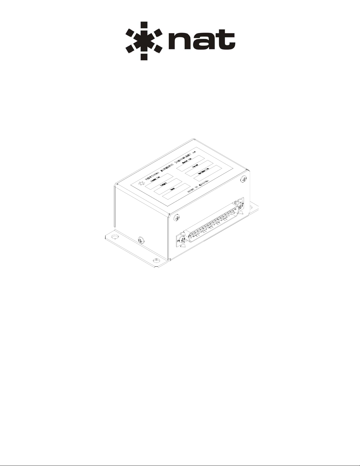
AA39 Series
Headset Adapters
SM43
ISSUE 4.01
Northern Airborne Technology Ltd.
1925 Kirschner Road
Kelowna, BC, Canada.
V1Y 4N7
Telephone (250) 763-2232
Facsimile (250) 762-3374
Issued on the authority of Northern Airborne Technology Ltd.
Copyright 2000
Page 2
AA39 Series Headset Adapters
SM43 Installation and Operation Manual
Prepared By: Checked By: Approved By:
The status of this installation and operation manual is controlled by issue shown on the title page. The
status of each section is controlled by revision shown in the footer of each page. All revisions affecting
sections of this manual have been incorporated into the latest issue.
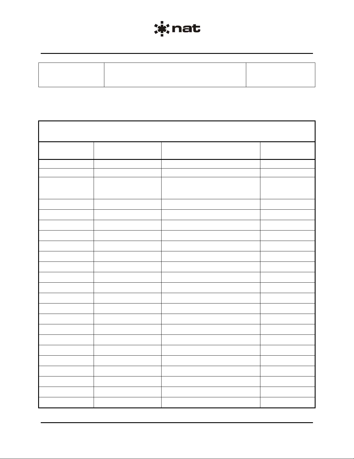
ISSUE/REVISION RECORD
Manual Issue
Number
1.00 N/A Initial release Aug 25, 2000
4.00 N/A Split Manual Nov 10, 2003
4.01 Section 1 Rev: 1.00
Section
Revision Number
Section 2 Rev: 1.00
Section 3 Rev: 1.00
Revision Description Issue Date
Rewrite in new format Jun 5, 2008
Installation and Operation Manual Page ii
ENG-FORM: 820-0114.DOT
CONFIDENTIAL AND PROPRIETARY TO NORTHERN AIR BORNE TECHNOLOGY LTD.
Page 3

AA39 Series Headset Adapters
SM43 Installation and Operation Manual
Table of Contents
Section Title Page
1. Description
1.1 Introduction 1-1
1.2 Product Description 1-1
1.3 Design Features 1-1
1.4 Specifications 1-1
1.4.1 Electrical Specifications 1-1
1.4.2 Physical Specifications 1-3
1.4.3 Environmental Specifications - AA39-187 and AA39-287 only 1-3
1.5 Unit Nomenclature 1-3
2. Installation
2.1 Introduction 2-1
2.2 Unpacking and Inspection 2-1
2.2.1 Warranty 2-1
2.3 Continued Airworthiness 2-1
2.4 Installation Procedures 2-1
2.4.1 Warnings 2-1
2.4.2 Cautions 2-2
2.4.3 Cabling and Wiring 2-2
2.4.4 Post-Installation Checks 2-3
2.5 Adjustments and Connections 2-3
2.6 Accessories Required But Not Supplied 2-4
2.6.1 Install Kit for AA39-075 and AA39-087 2-4
2.6.2 Install Kit for AA39-187 and AA39-287 2-4
2.7 Installation Drawings 2-4
3. Operation
3.1 Introduction 3-1
3.2 General Information 3-1
Installation and Operation Manual Page iii
ENG-FORM: 820-0114.DOT
CONFIDENTIAL AND PROPRIETARY TO NORTHERN AIR BORNE TECHNOLOGY LTD.
Page 4

AA39 Series Headset Adapter
SM43 Installation and Operation Manual
Section 1 Description
1.1 Introduction
Information in this section consists of product description, design features and specifications for the AA39
Series of Dynamic Headset Adapters.
The descriptions given are for the AA39-187, and are identical to those for other models unless otherwise
noted. All derivative product information shall be contained in the applicable manual supplement, which
may be obtained from NAT as required.
Review all notes, warnings and cautions.
1.2 Product Description
The AA39-187 is a single military headset adapter, consisting of a 5 Ω dynamic military mic to general
aviation 150 Ω amplified dynamic mic adaptor, with an 8 Ω to 600 Ω transformer for phones matching.
The AA39-287 operation is identical to the AA38-187, but is designed for two headsets.
The AA39-087 is used to adapt 5 Ω dynamic military mics (i.e. M-87) to general aviation 150 Ω audi o system s.
The AA39-075 is used to adapt 75 Ω dynamic military mics (i.e. ELNO) to general aviation 150 Ω audio systems.
1.3 Design Features
The AA39-075, AA39-087, AA39-187 and AA39-287 are small, remote mounted metal units with D-sub
connectors. The units are designed to operate from standard mic bi as, supplied by the aircraft radio and
intercom system.
1.4 Specifications
1.4.1 Electrical Specifications
1.4.1.1 AA39-075 and AA39-087
Input Power Not Applicable
Input Signals
Mic Bias: Nominal Bias Voltage: +12 Vdc
Maximum Bias Voltage: +16 Vdc
Minimum Bias Voltage: +9 Vdc
Other: Input current: 10 mA Max. @ Min Bias Voltage
Quantity: 1 Mic channel,
Audio level: AA39-075 850 μVrms for mic input
AA39-087 250 μVrms for mic input
Section 1 Rev: 1.00 Issue 4 Page 1-1
ENG-FORM: 800-0113.DOT
CONFIDENTIAL AND PROPRIETARY TO NORTHERN AIR BORNE TECHNOLOGY LTD.
Page 5

AA39 Series Headset Adapter
SM43 Installation and Operation Manual
Impedance: AA39-075 75 Ω ± 1 Ω for mic input
AA39-087 5 Ω ± 1 Ω for mic input
Circuitry Type: Balanced
Output Signals
Quantity: 1 mic output
Rated level: 250 mVrms into 150 Ω for mic output
Gain: Min. 1000 or 60 dB for mic amplifier (adjustable)
Circuitry Type: Single ended
1.4.1.2 AA39-187 and AA39-287
Input Power Not Applicable
Input Signals
Mic Bias: Nominal Bias Voltage: +12 Vdc
Maximum Bias Voltage: +16 Vdc
Minimum Bias Voltage: +9 Vdc
Other: Input current: 10 mA Max. @ Min Bias Voltage
Quantity: AA39-187 1 Mic input, 1 phones input
AA39-287 2 Mic inputs, 2 phones inputs
Audio level: 250 μVrms for mic input
7.7 Vrms for phones input
Impedance: 5 Ω ± 1 Ω for mic input
300 Ω ± 10% for phones input
(dependent on load impedance)
Circuitry Type: Balanced input for mic
Balanced transformer input for phones
Output Signals
Quantity: AA39-187 1 mic output, 1 phones output
AA39-287 2 mic outputs, 2 phones outputs
Rated level: 250 mVrms into 150 Ω for mic output
0.8 Vrms into 8 Ω for phones output
Gain: Min. 1000 or 60 dB for mic amplifier
Min. 8.5:1 ratio for phones transformer
Circuitry Type: Single ended output for mic
Balanced transformer output for phones
Freq. Resp. <3 dB from 350 Hz to 6000 Hz. for mic channel
<3 dB from 350 Hz to 6000 Hz. for phones channel
Distortion: <10% THD @ Rated power output
<3% THD @ 10% Continuous output
Audio Noise Level: Without Signal: <-50 dB from rated output
Coupling (AA39-287): Input to Input: ≤-40 dB from rated output
Section 1 Rev: 1.00 Issue 4 Page 1-2
ENG-FORM: 800-0113.DOT
CONFIDENTIAL AND PROPRIETARY TO NORTHERN AIR BORNE TECHNOLOGY LTD.
Page 6
AA39 Series Headset Adapter
SM43 Installation and Operation Manual
1.4.2 Physical Specifications
AA39-075 AA39-087 AA39-187 AA39-287
Height
Depth
Width
Weight
1.4.3 Environmental Specifications - AA39-187 and AA39-287 only
1.25” (32 mm) max 1.25” (32 mm) max 1.75” (45 mm) max 1.75” (45 mm) max
2.66” (67 mm) max 2.66” (67 mm) max 2.60” (66 mm) max 2.60” (66 mm) max
4.50” (114 mm) max 4.50” (114 m m ) max 4.50” (114 mm) max 4.50” (114 mm) max
0.25 lbs. (115 g) max 0.25 lbs. (115 g) max 0.44 lbs. (200 g) max 0.61 lbs. (277 g) max
Mounting Four 10-32 screws
Material/Finish Chassis & cover are 5052-H32 brushed aluminum with chromate
conversion finish
Connectors (-075, -087) One male 9-pin D-subminiature connector with screw jacks
(-187, -287) One filtered male 37-pin D-subminiature connector with
Positronics V5 locking tabs
DO-160C Env. Cat. [C4D1]-BA[MN]XXXXXXAXXXBTXXXX
Operating Temperatures -40° C to +70° C
Survival Temperatures -55° C to +85° C
Vibration/Shock DO-160C Cat. M/N
Humidity 95% @ ≥ RH for 48 hrs
Altitude 50,000 ft. Max.
Temperature Variation ± 5° C/min
Operational Shock and Operational: 6 g for 11 ms in all axes
Crash Safety Crash Safety (Impulse) 15 g for 11 ms in all axes
Crash Safety (Sustained) 12 g for 3 s in all axes
1.5 Unit Nomenclature
AA39-075 Military to general aviation mic adaptor
75 Ω Mid-Z mic interface (ELNO)
1 mic input - 850 μVrms into 75 Ω
1 mic output - 250 mVrms into 150 Ω
Powered by mic bias.
AA39-087 Military to general aviation mic adaptor
5 Ω Lo-Z mic interface (M87/M101)
1 mic input - 250 μVrms into 5 Ω
1 mic output - 250 mVrms into 150 Ω
Powered by mic bias.
Section 1 Rev: 1.00 Issue 4 Page 1-3
ENG-FORM: 800-0113.DOT
CONFIDENTIAL AND PROPRIETARY TO NORTHERN AIR BORNE TECHNOLOGY LTD.
Page 7

AA39 Series Headset Adapter
SM43 Installation and Operation Manual
AA39-187 Military Lo-Z to general aviation Hi-Z headset adaptor
1 mic input - 250 μVrms into 5 Ω
1 phones output - 0.8 Vrms into 8 Ω
1 mic output - 250 mVrms into 150 Ω
Powered by mic bias.
1 phones input - 7.7 Vrms into 600 Ω
AA39-287 Dual military Lo-Z to general aviation Hi-Z headset adaptor
2 mic inputs - 250 μVrms into 5 Ω
2 phones outputs - 0.8 Vrms into 8 Ω
2 mic outputs - 250 mVrms into 150 Ω
Powered by mic bias.
2 phones inputs - 7.7 Vrms into 600 Ω
Section 1 ends
Section 1 Rev: 1.00 Issue 4 Page 1-4
ENG-FORM: 800-0113.DOT
CONFIDENTIAL AND PROPRIETARY TO NORTHERN AIR BORNE TECHNOLOGY LTD.
Page 8

AA39 Series Headset Adapter
SM43 Installation and Operation Manual
Section 2 Installation
2.1 Introduction
Information in this section consists of unpacking and inspection procedures, installation procedures, postinstallation checks and installation drawings for the AA39 Series Headset Adapter.
Review all notes, warnings and cautions.
2.2 Unpacking and Inspection
Unpack the equipment carefully and locate the warranty card. Inspect the unit visually for damage due to
shipping and report all such claims immediately to the carrier involved. Check that all items listed below
are present before proceeding and report any shortage immediately to your supplier:
- Warranty Card
- Certificate of Conformity or Release Certification
2.2.1 Warranty
All Northern Airborne Technology Ltd. products are warranted for 2 years from date of installation by an
authorized NAT dealer, to be free of defects in workmanship or performance. This warranty covers all
materials and labour, but is exclusive of any transport to deliver the defective unit to and from NAT or its
designated warranty repair center, or any labour to remove or re-install the defective unit in the aircraft.
Contact NAT for any questions regarding this warranty, its applicability to your units and/or for return
authorization. NAT is the final arbitrator concerning warranty administration. Units which have been
physically damaged, burned, immersed in water or otherwise abused beyond the scope of normal use will
not be considered for warranty. WARRANTY IS VOID UNLESS THE PRODUCT IS INSTALLED BY AN
AUTHORIZED NAT DEALER. Product for which a warranty card is not returned shall be warranted from
date of manufacture.
2.3 Continued Airworthiness
Maintenance of the AA39 Series Headset Adapter is ‘on condition’ only. Periodic maintenance of this
product is not required.
2.4 Installation Procedures
2.4.1 Warnings
WARNING:
High volume settings can cause hearing damage.
Set the headset volume control to the minimum volume setting prior to
conducting tests, and slowly increase the headset volume to a
comfortable listening level.
Section 2 Rev: 1.00 Issue 4 Page 2-1
ENG-FORM: 805-0115.DOT
CONFIDENTIAL AND PROPRIETARY TO NORTHERN AIR BORNE TECHNOLOGY LTD.
Page 9

AA39 Series Headset Adapter
SM43 Installation and Operation Manual
2.4.2 Cautions
In all installations, use shielded cable exactly as shown, and ground as indicated.
Significant problems may result from not following these guidelines.
All audio installations can be seriously degraded by incorrect wiring and shielding, and
may result in abnormal crosstalk, hum and ground-loop noise. Be especially careful
with all microphone wiring and tie line wiring, as these lines carry the lowest level
signals in the aircraft.
Do not bundle any lines from this unit with transmitter coax lines. Do not
bundle any audio or DC power lines from this unit with 400 Hz synchro wiring
or AC power lines. Do not position this unit or wiring from this unit next to any
device with a strong alternating magnetic field such as an inverter, or
significant audio interference will result.
2.4.3 Cabling and Wiring
CAUTION:
CAUTION:
All wire shall be selected in accordance with the original aircraft manufacturer's Maintenance Instructions
or AC43.13-1B Change 1, Paragraphs 11-76 through 11-78. Unshielded wire types shall qualify to
MIL-W-22759 as specified in AC43.13-1B Change 1, Paragraphs 11-85, 11-86, and listed in Table 11-11.
For shielded wire applications, use Tefzel MIL-C-27500 shielded wire with solder sleeves (for shield
terminations) to make the most compact and easily terminated interconnect. Follow the connector map in
Section 2.7 as required.
Allow 3" from the end of the shielded wiring to the shield termination to allow the connector hood to be
easily installed. Reference the interconnect drawing in Section 2.7 for shield termination details. Note that
the hood is a "clamshell" hood, and is installed after the wiring is complete. Aircraft harnessing shall
permit the unit to be lowered from the panel for easy access to all side adjustments. Do NOT mount the
unit until all adjustments have been performed.
Maintain wire segregation and route wiring in accordance with the original aircraft manufacturers
Maintenance Instructions.
Unless otherwise noted, all wiring shall be a minimum of 24 AWG, except power and ground lines, which
shall be a minimum of 22 AWG. Reference the Interconnect drawing for additional specifications. Check
that the ground connection is clean and well secured, and that it shares no path with any electrically noisy
aircraft accessories such as blowers, turn and bank instruments or similar loads. Power to this unit must
be supplied from a separate circuit breaker or fuse (fast blow), and not attached to any other circuit
breaker without additional protection. Verify that the selected circuit breaker size and wire gauge are
adequate for the installation using the techniques specified in AC43.13-1B Change 1, Paragraphs 11-47
through 11-51 and 11-66 through 11-69.
2.3.4.1 Microphone Wiring
In all installations that use Dynamic microphones, extreme care must be taken with the shielding and
routing of the microphone wiring. This is especially true of the 5-ohm Dynamic mic input, where typical
signals are in the range of 100-250 μVrms. Special wire with Mumetal shielding should be considered if
there are any concerns about installation-related noise. Do not bundle the microphone wiring with high-
level lines (headphone, radio audio, coaxial cables, etc.).
Section 2 Rev: 1.00 Issue 4 Page 2-2
ENG-FORM: 805-0115.DOT
CONFIDENTIAL AND PROPRIETARY TO NORTHERN AIR BORNE TECHNOLOGY LTD.
Page 10

AA39 Series Headset Adapter
SM43 Installation and Operation Manual
Headset and/or helmet wiring may also need to be reviewed if using Dynamic microphones. Many of the
headsets and helmets on the market have minimal shielding for the wiring associated with the mic and
phone circuits. Those with shielded wiring often use the Phone Lo connection for the shield ground. In
the AA39, the Phone Lo connection is not ground referenced, so the shielding has no effect. This will
result in substantial coupling of the Phone signal onto the Microphone wires, leading to high levels of
crosstalk in the intercom system. These shielding considerations also apply to in-line PTT cordsets. If a
review of the headset wiring indicates there will be a problem with the shield termination, it is acceptable
to ground the Phone Lo connection to a local ground at the headset jack/connector.
2.4.4 Post-Installation Checks
2.4.4.1 Voltage/Resistance Checks
Do not attach the AA39 until the following conditions are met.
Check the following:
AA39-075 and AA39-087
Check J101, pin <9> for continuity to ground (less than 0.5 Ω).
AA39-187 and AA39-287
Check J1, pin <4> for continuity to ground (less than 0.5 Ω).
2.4.4.2 Power On Checks
Power up the aircraft’s systems and confirm normal operation of all functions of the AA39.
Upon satisfactory completion of all performance checks, make all required log book entries, electrical
load, weight and balance amendments and other documentation as required by your local regulatory
agency before releasing the aircraft for service.
2.5 Adjustments and Connections
The AA39-075 and AA39-087 have a MIC LEVEL adjustment trimpot, accessible through a hole in the
rear of the unit. Rotating the trimpot cw will increase the mic level, and ccw will decrease it.
There are no adjustments for the AA39-187 or AA39-287.
Section 2 Rev: 1.00 Issue 4 Page 2-3
ENG-FORM: 805-0115.DOT
CONFIDENTIAL AND PROPRIETARY TO NORTHERN AIR BORNE TECHNOLOGY LTD.
Page 11

AA39 Series Headset Adapter
SM43 Installation and Operation Manual
2.6 Accessories Required But Not Supplied
2.6.1 Install Kit for AA39-075 and AA39-087
Installation kit p/n AA39-IKC (crimp) is required to complete the installation. The kit consists of the following:
AA39-IKC (NAT Part No. D09SL-IKC)
Quantity Description NAT Part #
1 D-min 9 Socket Housing 20-21-009
9 MS Crimp Socket 20-26-901
1* Jack Screw Set 20-27-002
1* Lock Clip set 20-27-004
1 9 Pin Connector Hood 20-29-009
* Use as required.
2.6.2 Install Kit for AA39-187 and AA39-287
Installation kit p/n AA35-IKC-1 (crimp) is required to complete the installation. The kit consists of the following:
AA35-IKC-1 (NAT Part No. D37SV-IKC)
Quantity Description NAT Part #
1 D-min 37 Socket Housing 20-21-037
37 MS Crimp Socket 20-26-901
1 37 Pin JVL Hood/Locklever 20-29-370
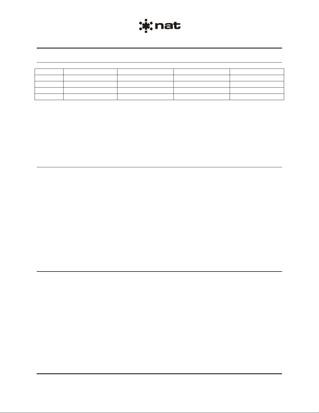
2.7 Installation Drawings
TYPE
DRAWING REV. DESCRIPTION
SERIAL NO.
AA39-075
AA39\075\403-0 - Mid Impedance Mic Interface Interconnect All
AA39\075\405-0 - Mid Impedance Mic Interface Connector Map All
AA39\075\922-0 1.00 Mid Impedance Mic Interface Mech. Installation All
AA39-087
AA39\087\403-0 - Low Impedance Mic Interface Interconnect All
AA39\087\405-0 - Low Impedance Mic Interface Connector Map All
AA39\087\922-0 1.00 Low Impedance Mic Interface Mech. Installation All
AA39-187
AA39\187\403-0 1.00 Dynamic Headset Adapter Interconnect All
AA39\187\405-0 1.00 Dynamic Headset Adapter Connector Map All
AA39\187\922-0 1.00 Dynamic Headset Adapter Mech. Installation All
AA39-287
AA39\287\403-0 1.00 Dual Dynamic Headset Adapter Interconnect All
AA39\287\405-0 1.00 Dual Dynamic Headset Adapter Connector Map All
AA39\287\922-0 1.00 Dual Dynamic Headset Adapter Mech. Installation All
Section 2 ends following the above documents
Section 2 Rev: 1.00 Issue 4 Page 2-4
ENG-FORM: 805-0115.DOT
CONFIDENTIAL AND PROPRIETARY TO NORTHERN AIR BORNE TECHNOLOGY LTD.
Page 12

Confidential and Proprietary to NAT
Page 13

Confidential and Proprietary to NAT
Page 14

Page 15

Confidential and Proprietary to NAT
Page 16

Confidential and Proprietary to NAT
Page 17

Page 18

Confidential and Proprietary to NAT
Page 19

Confidential and Proprietary to NAT
Page 20

Confidential and Proprietary to NAT
Page 21

Confidential and Proprietary to NAT
Page 22

Confidential and Proprietary to NAT
Page 23

Confidential and Proprietary to NAT
Page 24

AA39 Series Headset Adapter
SM43 Installation and Operation Manual
Section 3 Operation
3.1 Introduction
Information in this section consists of the functional and operational procedures for the AA39 Series
Headset Adapter.
3.2 General Information
The AA39-187 is a single military headset adapter, consisting of a 5 Ω dynamic military mic to general
aviation 150 Ω amplified dynamic mic adaptor, with an 8 Ω to 600 Ω transformer for phones matching.
The AA39-287 operation is identical to the AA38-187, but is designed for two headsets.
The AA39-087 is used to adapt 5 Ω dynamic military mics (i.e. M-87) to general aviation 150 Ω audi o system s.
The AA39-075 is used to adapt 75 Ω dynamic military mics (i.e. ELNO) to general aviation 150 Ω audio systems.
The AA39 Series Headset Adapters have no operator accessible controls. During installation, it may be
determined that internal level adjustments are required. Qualified personnel only shall complete internal
level adjustments.
Section 3 ends
Section 3 Rev: 1.00 Issue 4 Page 3-1
ENG-FORM: 806-0111.DOT
CONFIDENTIAL AND PROPRIETARY TO NORTHERN AIR BORNE TECHNOLOGY LTD.
 Loading...