

Page 1
Installation and Operation Manual
AA38-5xx, -6xx, -7xx and -8xx Series
Local ICS Loop
SM54
ISSUE 4.11
Northern Airborne Technology Ltd.
1925 Kirschner Road
Kelowna, BC, Canada.
Telephone (250) 763-2232
Facsimile (250) 762-3374
Issued on the authority of Northern Airborne Technology Ltd.
Copyright 2008
V1Y 4N7
Page 2
AA38-5xx, -6xx, -7xx and -8xx Series Local ICS Loop
SM54 Installation and Operation Manual
Prepared By: Checked By: Approved By:
The status of this installation and operation manual is controlled by issue shown on the title page. The
status of each section is controlled by revision shown in the footer of each page. All revisions affecting
sections of this manual have been incorporated into the latest issue.
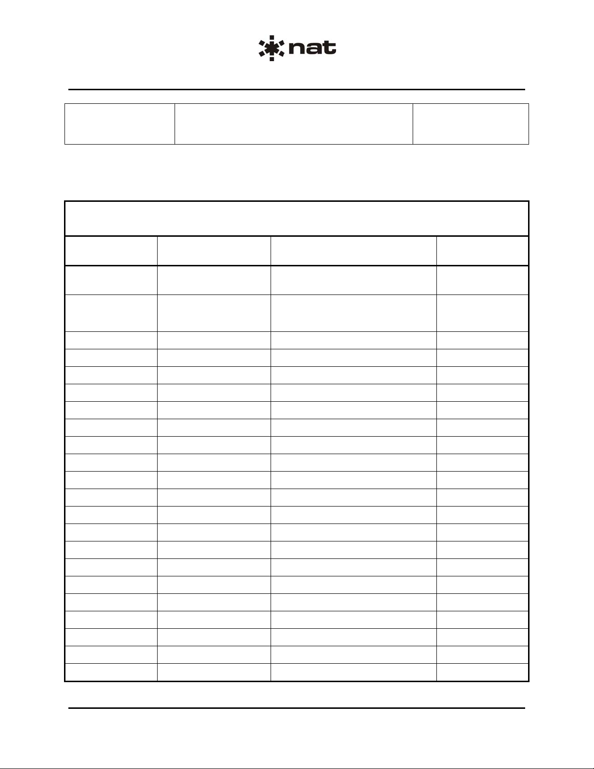
ISSUE/REVISION RECORD
Manual Issue
Number
Section
Revision Number
Revision Description Issue Date
4.11 Section 1 Rev: 1.01 Remove reference to Environmental
Qualification Form.
4.10 Section 1 Rev: 1.00
Section 2 Rev: 1.00
Section 3 Rev: 1.00
Update to current templates. Jun 9, 2008
Jan 13, 2010
Installation and Operation Manual Page ii
ENG-FORM: 820-0115.DOT
CONFIDENTIAL AND PROPRIETARY TO NORTHERN AIRBORNE TECHNOLOGY LTD.
Page 3

AA38-5xx, -6xx, -7xx and -8xx Series Local ICS Loop
SM54 Installation and Operation Manual
Table of Contents
Section Title Page
1. Description
1.1 Introduction 1-1
1.2 Product Description 1-1
1.3 Design Features 1-1
1.4 Specifications 1-2
1.4.1 Electrical Specifications 1-2
1.4.2 Physical Specifications 1-4
1.4.3 Environmental Specifications 1-4
1.5 Unit Nomenclature 1-5
2. Installation
2.1 Introduction 2-1
2.2 Unpacking and Inspection 2-1
2.2.1 Warranty 2-1
2.3 Continued Airworthiness 2-1
2.4 Installation Procedures 2-2
2.4.1 Cabling and Wiring 2-2
2.4.2 Post Installation Checks 2-2
2.5 Adjustments and Connections 2-3
2.5.1 Headset Volume and Sensitivity Adjustments 2-4
2.5.2 Auxiliary Receive control(s) 2-4
2.5.3 Mode Control (AA38-5xx and -6xx) 2-4
2.5.4 Mode control (AA38-7xx and AA38-8xx) 2-5
2.5.5 Remote ICS Master Volume Control (AA38-7xx and AA38-802) 2-7
2.6 Accessories Required But Not Supplied 2-7
2.7 Installation Drawings 2-7
3. Operation
3.1 Introduction 3-1
3.2 General Information 3-1
3.3 Controls and Indicators 3-1
3.3.1 AA38-5xx and AA38-6xx 3-1
3.3.2 Master ICS Volume Control (AA38-7xx and AA38-8xx) 3-1
Installation and Operation Manual Page iii
ENG-FORM: 820-0115.DOT
CONFIDENTIAL AND PROPRIETARY TO NORTHERN AIR BORNE TECHNOLOGY LTD.
Page 4

AA38-5xx, -6xx, -7xx and -8xx Series Local ICS Loop Manual
SM54 Installation and Operation Manual
Section 1 Description
1.1 Introduction
Information in this section consists of product description, design features and specifications for the
AA38-5xx, -6xx, -7xx and -8xx Series Local ICS Loop Manual. All derivative product information shall be
contained in the applicable manual supplement, which may be obtained from Northern Airborne
Technology Ltd as required.
Review all notes, warnings and cautions.
1.2 Product Description
The AA38-5xx Series Local ICS Loops (not AA38-505) provide live, VOX or keyed ICS for 4 or 8 users
(depending on model) with low impedance headsets.
The AA38-6xx Series Local ICS Loops provide live, VOX or keyed ICS for 4 or 8 users (depending on
model) with high impedance headsets.
The AA38-7xx Series Local ICS Loops provide an external ICS Volume control, and live, VOX or keyed
ICS for 4 users with low impedance headsets.
The AA38-8xx Series Local ICS Loops provide an external ICS Volume control, and live, VOX or keyed
ICS for 8 users with high impedance headsets.
The AA38-503, AA38-603 and AA38-703 models have prioritized transmit capabilities for all users, with
the highest priority given to user #1 and lowest to user #4.
The AA38-505 Series Local ICS Loops provide live, VOX or keyed ICS for 4 users with high impedance
headsets.
1.3 Design Features
The AA38-5xx, -6xx, -7xx and -8xx Series Local ICS Loops are remote, bulkhead mounted units
containing all the circuitry required to support a wide variety of ICS Loop applications, particularly
isolation/ICS amplifier use, where the output is required to be headset or line level. A switch-selectable
NAT/Andrea (AA38-5xx or -6xx) or NAT/SuperNAT ICS tie line (AA38-7xx or AA38-8xx) allows
connection to larger audio systems, and an auxiliary input allows for audio input from an audio panel or
transceiver.
The compact size and low weight of the AA38-5xx, -6xx, -7xx and -8xx Series Local ICS Loops allows
mounting in restricted locations, and the mapped interconnect makes installation simple to carry out.
ICS level and VOX sensitivity adjustments are provided for each headset position and for the AUX level.
The operational performance of the AA38 unit can be enhanced for specific operating roles with the
addition of in-line PTT drop cords. Drop cords can be configured to allow individual selection of headset
volume, intercom operation in VOX, LIVE or PTT mode, and independent TX PTT capability for those
AA38 models equipped with TX functions.
Section 1 Rev: 1.01 Issue 4 Page 1-1
ENG-FORM: 800-0116.DOT
CONFIDENTIAL AND PROPRIETARY TO NORTHERN AIR BORNE TECHNOLOGY LTD.
Page 5

AA38-5xx, -6xx, -7xx and -8xx Series Local ICS Loop Manual
SM54 Installation and Operation Manual
1.4 Specifications
1.4.1 Electrical Specifications
Power Supply
Input Signals
Section 1 Rev: 1.01 Issue 4 Page 1-2
ENG-FORM: 800-0116.DOT
Type DC Linear
Input Voltage Typically +24.8 to +30.3 Vdc
Nominal +27.5 Vdc (with reverse & over voltage protection)
Emergency +20.0 Vdc
Input Current 0.45 A Max. @ +27.5 Vdc (AA38-501, -503, -504, -505)
0.80 A Max. @ +27.5 Vdc (AA38-502, -602)
0.41 A Max. @ +27.5 Vdc (AA38-601, -603)
0.35 A Max. @ +27.5 Vdc (AA38-703)
0.90 A Max. @ +27.5 Vdc (AA38-802)
Quantity 8 MIC channels
(AA38-502, -602 and -802) 2 ICS tie channels, one for each group of 4 users
2 AUX RX channels, each driving 4 users
Quantity 4 MIC channels
(except AA38-502, 1 ICS tie channel
-602 or -802) 1 AUX RX channel
Audio Level 250 µVrms for MIC inputs (AA38-5xx except -505, -7xx models)
1.1 mVrms for MIC inputs (AA38-505 model only)
250 mVrms for MIC inputs (AA38-6xx models only)
340 mVrms for NAT ICS tie input(s)
2.8 Vrms for Andrea ICS tie input(s) (AA38-5xx and -6xx models)
2.5 Vrms for AUX RX input
1.2 Vrms (typical) for SuperNAT ICS (AA38-7xx and -8xx)
Circuitry Type Tie lines are single ended inputs
All AA38-5xx model MICs are differential inputs
All AA38-6xx model MICs are single ended inputs
All AA38-7xx model MICs are differential inputs
All AA38-8xx model MICs are balanced inputs
All AUX RX inputs are balanced
Keylines 4 ICS PTT active low (AA38-501, -504, -505, -60 1)
8 ICS PTT active low (AA38-502, -602, -802)
4 ICS PTT active low (AA38-503, -603, -703)
4 TX PTT active low
CONFIDENTIAL AND PROPRIETARY TO NORTHERN AIR BORNE TECHNOLOGY LTD.
Page 6

Output Signals
Quantity 4 Headphone outputs (AA38-501, -503, -504, -505, -601, -603, -703)
8 Headphone outputs (AA38-502, -602, -802)
Rated Level Selectable between 8 and 600 Ω (except AA38-703 or -802)
7.7 Vrms or 100 mW (20 dBm) into 600 Ω (except AA38-703)
0.9 Vrms or 100 mW (20 dBm) into 8 Ω (except AA38-802)
ICS Tie Output level selectable between 1.6 kΩ (NAT ICS tie) and 250 Ω
(except AA38-504, (Andrea ICS tie)
AA38-703 and AA38-802) 140 mVrms ±10% for NAT ICS tie output (4 NAT loads)
2.8 Vrms ±10% for Andrea ICS tie output
ICS Tie Output level selectable between 1.6 kΩ (NAT ICS tie) and 250 Ω
(AA38-504 only) (Andrea ICS tie)
300 mVrms ±10% for NAT ICS tie output (1 NAT load)
3.8 Vrms ±10% for Andrea ICS tie output
ICS Tie 340 ±50 mVrms for NAT ICS tie output (1 NAT load)
(AA38-703 only) 1.2 ±0.1 Vrms for SuperNAT ICS tie output (1 to 4 SuperNAT
ICS Tie 340 ±50 mVrms for NAT ICS tie output (2 NAT loads)
(AA38-802 only) 1.2 ±0.1 Vrms for SuperNAT ICS tie output (1 to 8 SuperNAT
Impedance / Output 1-4 x 600 Ω or 1-4 x 8 Ω
1-8 x 600 Ω or 1-8 x 8 Ω (AA38-502 and -602 only)
2 ±0.2 kΩ for NAT ICS tie line
2 ±0.2 kΩ for SuperNAT ICS tie line (AA38-703 and -802 only)
Phones Circuitry Type Balanced output for high common mode noise rejection
ICS Tie Line Circuitry Type Single ended
Frequency Response ICS: ≤3 dB from 350 to 3000 Hz
MIC Input: ≤3 dB from 350 to 3000 Hz
AUX RX Input: ≤3 dB from 350 to 6000 Hz
Distortion ≤10% THD @ rated power output
Audio Noise Level ≤-60 dB from rated output (without signal)
Coupling ≤-50 dB input to output crosstalk
Output Regulation at 400% ≤10% distortion / Δ 3dB max rated output power for 600 Ω output
and 75% of rated load ≤10% distortion / Δ 7dB max rated output power for 8 Ω output
AA38-5xx, -6xx, -7xx and -8xx Series Local ICS Loop Manual
SM54 Installation and Operation Manual
loads)
loads)
Section 1 Rev: 1.01 Issue 4 Page 1-3
ENG-FORM: 800-0116.DOT
CONFIDENTIAL AND PROPRIETARY TO NORTHERN AIR BORNE TECHNOLOGY LTD.
Page 7
AA38-5xx, -6xx, -7xx and -8xx Series Local ICS Loop Manual
SM54 Installation and Operation Manual
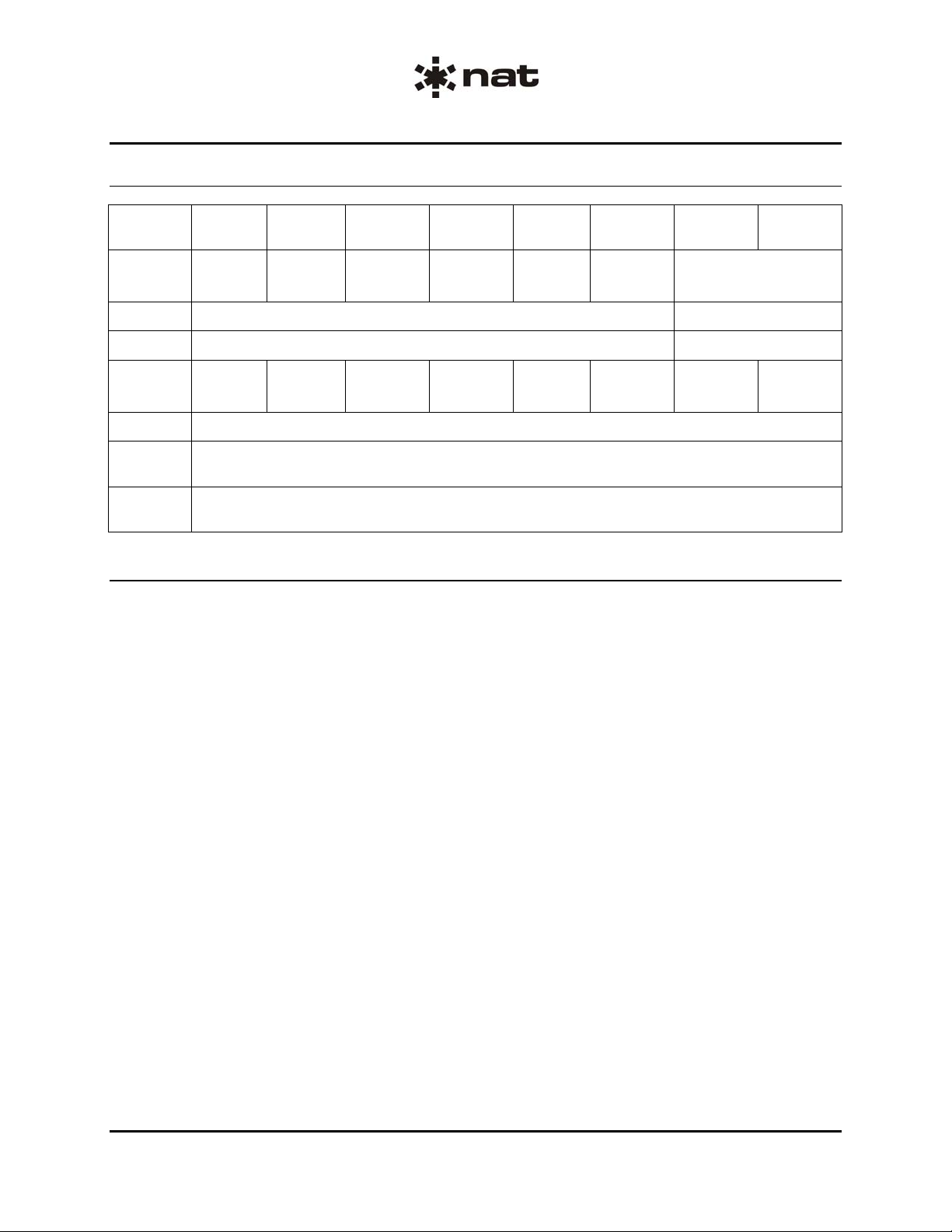
1.4.2 Physical Specifications
AA38-501,
-504, -505
AA38-502 AA38-503 AA38-601 AA38-602 AA 38-603 AA38-703 AA38-802
Height
Max.
Depth 4.88" (124.0 m m) max. including connecto r 4.95" (125.7 mm)
Width 5.91" (150.1 mm) max. including flanges 5.94" (150.9 mm)
Weight
Max.
Mounting Bulkhead mount with four 10-32 screws
Material/
Finish
Connectors
1.18"
(30.0 mm)
1.14 lbs
(0.52 Kg)
2.26”
(57.4 mm)
2.00 lbs
(0.91 Kg)
Filtered male 37-pin D-subminiature connector with Positronics V5 locking tabs.
1.90"
(48.3 mm)
1.40 lbs
(0.63 Kg)
5052-H32 brushed aluminum with chromate conversion finish
(Two in the AA38-502, -503, -602, -603, -703 and -802)
1.18"
(30.0 mm)
0.80 lbs
(0.36 Kg)
2.26”
(57.4 mm)
1.37 lbs
(0.6 Kg)
1.90"
(48.3 mm)
1.20 lbs
(0.54 Kg)
1.60 lbs
(0.7 Kg)
1.94"
(49.3 mm)
1.4.3 Environmental Specifications
Temperature -45 to +55°C (ambient)
-55 to +85°C (survival)
Altitude 35,000 feet max.
Humidity 95% for 48 hours
Vibration/Shock Conforms to DO-160C category B, M, N
Qualification of the AA38-5xx Local ICS Loop was completed in accordance with
DO-160C Env. Cat. A1C4-BA[BMN]XXXXXXABABBTBXXX.
Qualification of the AA38-6xx Local ICS Loop was completed in accordance with
DO-160C Env. Cat. A1C4-BA[BMN]XXXXXXABABBTBXXX.
Qualification of the AA38-703 Local ICS Loop was completed in accordance with
DO-160C Env. Cat. A1C4-BA[BMN]XXXXXXZBABXXB
DO-160D Env. Cat. XX-XXXXXXXXXXXXXXXS
1
RF Susceptibility testing was performed to DO-160D, change 1, Sec. 20, Cat. S.
1
1
XXXXX.
XXX.
Note: The AA38-802 has not been tested for compliance to any DO-160 categories at this time.
1.44 lbs
(0.69 Kg)
Section 1 Rev: 1.01 Issue 4 Page 1-4
ENG-FORM: 800-0116.DOT
CONFIDENTIAL AND PROPRIETARY TO NORTHERN AIR BORNE TECHNOLOGY LTD.
Page 8

AA38-5xx, -6xx, -7xx and -8xx Series Local ICS Loop Manual
SM54 Installation and Operation Manual
1.5 Unit Nomenclature
AA38-501 LO Z Local ICS Loop - Four Place Intercom
4 MIC inputs - 0.250 mV / 5 Ω
1 ICS Tie line - 1.6 kΩ (NAT) or 250 Ω (Andrea)
1 AUX input - 1 kΩ
4 headset outputs 100 mW @ 8 or 600 Ω
Balanced output for high common mode noise rejection
LIVE, VOX or PTT operation
AA38-502 LO Z Local ICS Loop - Eight Place Intercom
8 MIC inputs - 0.250 mV / 5 Ω
2 ICS Tie lines - 1.6 kΩ (NAT) or 250 Ω (Andrea)
2 AUX inputs - 1 kΩ
8 headset outputs 100 mW @ 8 or 600 Ω
Balanced output for high common mode noise rejection
LIVE, VOX or PTT operation
AA38-503 LO Z Local ICS Loop - Four Place Intercom with Transmit
4 MIC inputs - 0.250 mV / 5 Ω
1 ICS Tie line - 1.6 kΩ (NAT) or 250 Ω (Andrea)
1 AUX input - 1 kΩ
4 headset outputs 100 mW @ 8 or 600 Ω
Balanced output for high common mode noise rejection
LIVE, VOX or PTT operation
Individual TX PTT for each user (ascending priority)
AA38-504 LO Z Local ICS Loop - Four Place Intercom, High Gain Microphones
4 MIC inputs - 0.250 mV at 5 Ω
1 ICS Tie line input - 1.6 kΩ (NAT) or 250 Ω (Andrea)
1 AUX input - 1 kΩ
4 headset outputs 100 mW @ 8 or 600 Ω
Balanced output for high common mode noise rejection
LIVE, VOX or PTT operation
AA38-505 Hi Z Local ICS Loop - Four Place Intercom
4 MIC inputs – 1.1 mV / 150 Ω
1 ICS Tie line - 1.6 kΩ (NAT) or 250 Ω (Andrea)
1 AUX input - 1 kΩ
4 headset outputs 100 mW @ 8 or 600 Ω
Balanced output for high common mode noise rejection
LIVE, VOX or PTT operation
AA38-601 Hi Z Local ICS Loop - Four Place Intercom
4 MIC inputs - 250 mV / 150 Ω
1 ICS Tie line - 1.6 kΩ (NAT) or 250 Ω (Andrea)
1 AUX input - 1 k Ω
4 headset outputs 100 mW @ 8 or 600
Balanced output for high common mode noise rejection
LIVE, VOX or PTT operation
Section 1 Rev: 1.01 Issue 4 Page 1-5
ENG-FORM: 800-0116.DOT
CONFIDENTIAL AND PROPRIETARY TO NORTHERN AIR BORNE TECHNOLOGY LTD.
Ω
Page 9

AA38-5xx, -6xx, -7xx and -8xx Series Local ICS Loop Manual
SM54 Installation and Operation Manual
AA38-602 Hi Z Local ICS Loop - Eight Place Intercom
8 MIC inputs - 250 mV / 150 Ω
2 ICS Tie lines - 1.6 kΩ (NAT) or 250 Ω (Andrea)
2 AUX inputs - 1 kΩ
8 headset outputs 100 mW @ 8 or 600 Ω
Balanced output for high common mode noise rejection
LIVE, VOX or PTT operation
AA38-603 Hi Z Local ICS Loop - Four Place Intercom with Transmit
4 MIC inputs - 250 mV / 150 Ω
1 ICS Tie line - 1.6 kΩ (NAT) or 250 Ω (Andrea)
1 AUX input - 1 k Ω
4 headset outputs 100 mW @ 8 or 600 Ω
Balanced output for high common mode noise rejection
LIVE, VOX or PTT operation
Individual TX PTT for each user (ascending priority)
AA38-703 LO Z Local ICS Loop - Four Place Intercom with Transmit, External ICS Volume
4 MIC inputs - 0.250 mV / 5 Ω
1 ICS Tie line - 2 ±0.2 kΩ for NAT and SuperNAT
1 AUX input - 1 kΩ
4 headset outputs 100 mW @ 8 Ω
Balanced output for high common mode noise rejection
LIVE, VOX or PTT operation
Individual TX PTT for each user (ascending priority)
External ICS Volume Control
AA38-802 Hi-Z Eight Place Intercom - with Master Volume
8 MIC inputs - 250 mV / 150 Ω
2 ICS Tie line - 2 ±0.2 kΩ for NAT and SuperNAT
2 RX inputs - 1 kΩ
8 headset outputs 100 mW @ 600 Ω
Balanced output for high common mode noise rejection
LIVE, VOX or PTT operation
External ICS Volume Control
Section 1 ends
Section 1 Rev: 1.01 Issue 4 Page 1-6
ENG-FORM: 800-0116.DOT
CONFIDENTIAL AND PROPRIETARY TO NORTHERN AIR BORNE TECHNOLOGY LTD.
Page 10

AA38-5xx, -6xx, -7xx and -8xx Series Local ICS Loop
SM54 Installation and Operation Manual
Section 2 Installation
2.1 Introduction
Information in this section consists of unpacking and inspection procedures, installation procedure s, po stinstallation checks and installation drawings for the AA38-5xx, -6xx, -7xx and -8xx Series Local ICS Loop.
Review all notes, warnings and cautions.
2.2 Unpacking and Inspection
Unpack the equipment carefully and locate the warranty card. Inspect the unit visually for damage due to
shipping and report all such claims immediately to the carrier involved. Check that all items listed below
are present before proceeding and report any shortage immediately to your supplier:
- Warranty Card
- Certificate of Conformity or Release Certification
2.2.1 Warranty
All Northern Airborne Technology Ltd. products are warranted for 2 years from date of installation by an
authorized NAT dealer, to be free of defects in workmanship or performance. This warranty covers all
materials and labour, but is exclusive of any transport to deliver the defective unit to and from NAT or its
designated warranty repair center, or any labour to remove or re-install the defective unit in the aircraft.
Contact NAT for any questions regarding this warranty, its applicability to your units and/or for return
authorization. NAT is the final arbitrator concerning warranty administration. Units which have been
physically damaged, burned, immersed in water or otherwise abused beyond the scope of normal use will
not be considered for warranty. WARRANTY IS VOID UNLESS THE PRODUCT IS INSTALLED BY AN
AUTHORIZED NAT DEALER. Product for which a warranty card is not returned shall be warranted from
date of manufacture.
2.3 Continued Airworthiness
Maintenance of the AA38-5xx, -6xx, -7xx and -8xx Series Local ICS Loop is ‘on condition’ only. Periodic
maintenance of this product is not required.
Section 2 Rev: 1.00 Issue 4 Page 2-1
ENG-FORM: 805-0115.DOT
CONFIDENTIAL AND PROPRIETARY TO NORTHERN AIR BORNE TECHNOLOGY LTD.
Page 11

AA38-5xx, -6xx, -7xx and -8xx Series Local ICS Loop
SM54 Installation and Operation Manual
2.4 Installation Procedures
2.4.1 Cabling and Wiring
All wire shall be selected in accordance with the original aircraft manufacturer's Maintenance Instructions
or AC43.13-1B Change 1, Paragraphs 11-76 through 11-78. Unshielded wire types shall qualify to
MIL-W-22759 as specified in AC43.13-1B Change 1, Paragraphs 11-85, 11-86, and listed in Table 11-11.
For shielded wire applications, use Tefzel MIL-C-27500 shielded wire with solde r sleeve s (fo r shield
terminations) to make the most compact and easily terminated interconnect. Follow the connector map in
Section 2.6 as required.
Coaxial cable shall be selected in accordance with MIL-C-17 unless otherwise specified. Do not use coax
cable with PVC insulation. Teflon dielectric cable is encouraged at or above VHF frequencies or where
cable runs exceed 8 feet. Note that at VHF frequencies, cables losses due to long cable runs and tight
bends may reduce the ERP (Effective Radiated Power) by greater than 50%.
Allow 3" from the end of the shielded wiring to the shield termination to allow the connector hood to be
easily installed. Reference the interconnect drawing in Section 2.6 for shield termination details. Note that
the hood is a "clamshell" hood, and is installed after the wiring is complete. Aircraft harnessing shall
permit the unit to be lowered from the panel for easy access to all side adjustments. Do NOT mount the
unit until all adjustments have been performed.
Maintain wire segregation and route wiring in accordance with the original aircraft manufacturers
Maintenance Instructions. Coaxial cables shall be routed separately from existing wire bundle s in the
aircraft to minimize electromagnetic coupling effects.
Unless otherwise noted, all wiring shall be a minimum of 24 AWG, except power and ground lines, which
shall be a minimum of 22 AWG. Reference the Interconnect drawing for additional specifications. Check
that the ground connection is clean and well secured, and that it shares no path with any electrically noisy
aircraft accessories such as blowers, turn and bank instruments or similar loads. Power to this unit must
be supplied from a separate circuit breaker or fuse (fast blow), and not attached to any other circuit
breaker without additional protection. Verify that the selected circuit breaker size and wire gauge are
adequate for the installation using the techniques specified in AC43.13-1B Change 1, Paragraphs 11-47
through 11-51 and 11-66 through 11-69.
2.4.2 Post Installation Checks
2.4.2.1 Voltage/Resistance Checks
Do not attach the AA38-5xx, -6xx, -7xx and -8xx Series Local ICS Loop until the following
conditions are met.
Check the following:
a) Check P101, pin 1 for +28 Vdc relative to ground.
b) Check P101, pin 20 for continuity to ground (less than 0.5 Ω).
c) Check P101 pins 3, 5, 7 and 9 for continuity to ground (less than 0.5 Ω) when relevant ICS
PTT line is keyed.
For AA38-502, AA38-602 and AA38-802, repeat this process for the same pins in P102.
Section 2 Rev: 1.00 Issue 4 Page 2-2
ENG-FORM: 805-0115.DOT
CONFIDENTIAL AND PROPRIETARY TO NORTHERN AIR BORNE TECHNOLOGY LTD.
Page 12

AA38-5xx, -6xx, -7xx and -8xx Series Local ICS Loop
SM54 Installation and Operation Manual
For AA38-503, AA38-603 and AA38-703, also check the following:
d) P102 pin 1 for +28 Vdc relative to ground.
e) P102 pin 20 for continuity to ground.
f) P102 pins 14, 15, 16 and 17 for continuity to ground when relevant TX PTT line is keyed.
For AA38-703, also check the following:
g) P102 pins 11 and 13 for continuity to ground when relevant ICS VOL switch is activated.
For AA38-802, also check the following:
h) P101 and P102 pins 11 and 13 for continuity to ground when relevant ICS VOL switch is
activated.
2.4.2.2 Power On Checks
Power up the aircraft’s systems and confirm normal operation of all functions of the AA38-5xx, -6xx, -7xx
and -8xx. Refer to Section 3 (Operation) for specific operational details.
a) Check for correct radio and intercom audio and adjust for acceptable level.
b) Run through all installed functions, and check the ICS and TX functions for all users.
c) Check preset adjustments are completed before aircraft departure.
Notes: 1. Significantly different headsets may have different MIC characteristics.
2. The David Clark M 7 MIC is more active than the M 4 or M 1/DC MICs. Mixing
different MICs may aggravate headset imbalance.
Upon satisfactory completion of all performance checks, make all required log book entries, electrical
load, weight and balance amendments and other documentation as required by your local regulatory
agency before releasing the aircraft for service.
2.5 Adjustments and Connections
The unit is shipped from the factory with all internal adjustments set to the normal test levels. Once
installed in the aircraft, it may be desirable to change some of these settings to best suit the local
operating environment. See Section 2.4 for the specific unit under consideration.
The AA38-5xx/6xx/7xx/8xx can be set for up to four NAT tie line configurations, one Andrea tie line
(AA38-5xx and -6xx) or up to four SuperNAT tie lines (AA38-7xx and AA38-802).
The internal adjustments that can be varied are located along the sides and at the rear of the unit. Refer
to Mechanical Installation drawings AA38/xxx/922-0 in Section 2.6 of this manual, where xxx is the model
number under consideration, ie. AA38/503/922-0.
Section 2 Rev: 1.00 Issue 4 Page 2-3
ENG-FORM: 805-0115.DOT
CONFIDENTIAL AND PROPRIETARY TO NORTHERN AIR BORNE TECHNOLOGY LTD.
Page 13
AA38-5xx, -6xx, -7xx and -8xx Series Local ICS Loop
SM54 Installation and Operation Manual
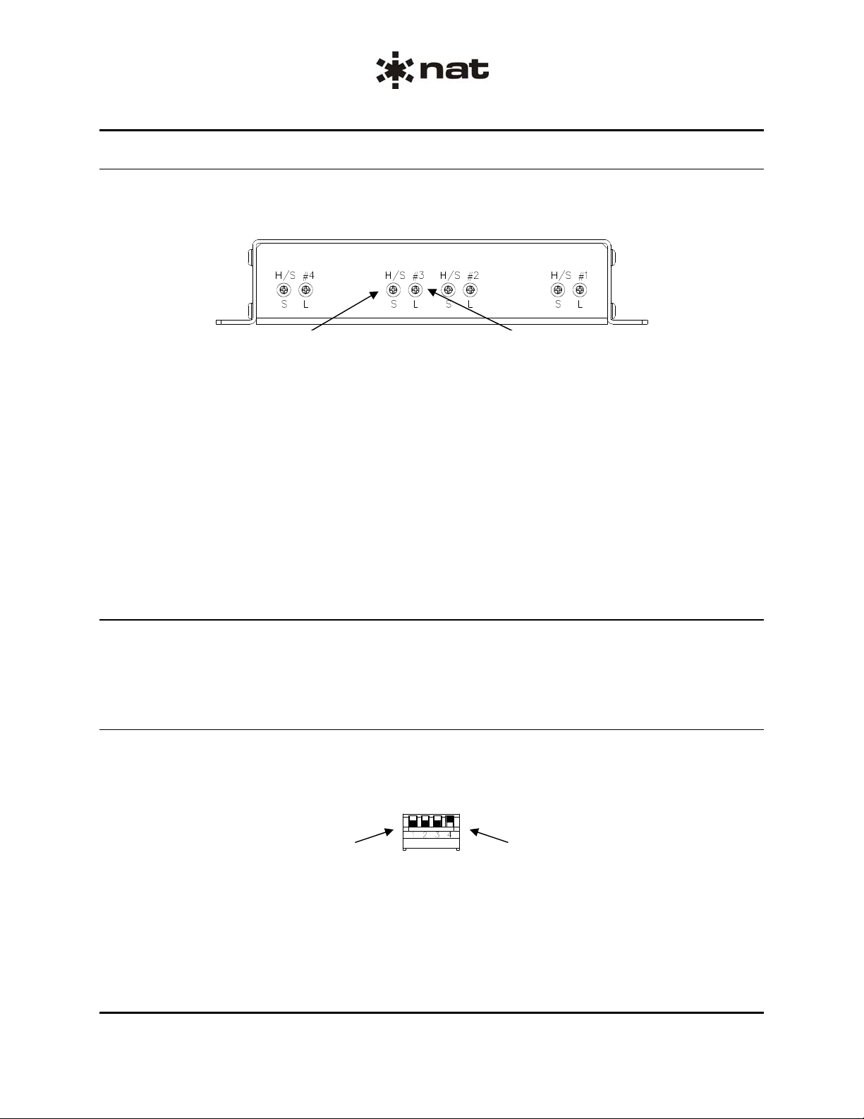
2.5.1 Headset Volume and Sensitivity Adjustments
The headset volume and sensitivity controls are located on the rear of the unit as shown in Figure 1
below. Each headset position has a level trimpot (L) and a sensitivity trimpot (S) that controls MIC/VOX
operation.
Headset #3 Level (Volume) Adjustment Headset #3 Sensitivity Adjustment
Figure 1: Headset Volume and Sensitivity Controls
The AA38-502, AA38-602 and AA38-802 have two banks of controls. The individual headset level
(volume) controls provide up to 40 dB of dynamic range. For maximum headset power rotate the pot fully
clockwise (cw) and for minimum headset power rotate fully counter-clockwise (ccw).
The individual sense control trimpots are used to select the required operating mode for the headset s. For
KEYED ICS (PTT operation) the trimpot is set fully cw. For LIVE (Hot MIC operation) the trimpot is set
fully ccw. For VOX (Voice Activated operation) the trimpot is set in the mid position.
To obtain the best setting for the ambient noise conditions and the quality and number of MICs connected
in the system, set the trimpot fully ccw, then slowly rotate it cw until the intercom just becomes ‘quiet’.
Check this setting for both ground and flight operation.
2.5.2 Auxiliary Receive control(s)
The Auxiliary (AUX) receive (RX) level trimpot (RX LEVEL) is located on the front of the unit, and provides
up to 40 dB of dynamic range. When rotated fully cw it gives maximum AUX RX input level, and fully ccw
gives minimum level. The AA38-502, AA38-602 and AA38-802 have two of these controls.
2.5.3 Mode Control (AA38-5xx and -6xx)
The Mode Control switch is used for selecting the type of ICS tie line configuration required and is a quad
piano DIP-switch accessible through the left side of the unit. To open a switch, place it in the ‘up’ position
and to close it put it in the ‘down’ position as shown in Figure 2.
Switches 1, 2 and 3 shown in the
closed (down) position.
Switch 4 shown in the open
(up) position.
Figure 2: Mode Control DIP Switch
Section 2 Rev: 1.00 Issue 4 Page 2-4
ENG-FORM: 805-0115.DOT
CONFIDENTIAL AND PROPRIETARY TO NORTHERN AIR BORNE TECHNOLOGY LTD.
Page 14

AA38-5xx, -6xx, -7xx and -8xx Series Local ICS Loop
SM54 Installation and Operation Manual
Tie Line Mode selection is accomplished by setting the Mode Control switch as shown in Figure 3 below.
TIE LINE MODE Selection Switch Position
ANDREA Tie Line
3 NAT Tie Lines (Default)
4 NAT Tie Lines
Figure 3: Tie Line Mode Selection
Andrea Tie Line Switch 2 and 3 closed (down)
Switch 4 open (up)
Switch 1 has no effect
3 NAT Tie Line Switch 1 and 4 closed (down)
Switch 2 and 3 open (up)
4 NAT Tie Line Switch 4 closed (down)
Switch 1, 2 and 3 open (up)
Note: All other switch combinations are invalid.
2.5.4 Mode control (AA38-7xx and AA38-8xx)
The AA38-7xx and AA38-8xx mode control is used in the same way as the AA38-5xx and -6xx models,
but is an 8-position switch accessible through the left side of the unit. To open a switch, place it in the ‘up’
position and to close it put it in the ‘down’ position as shown in Figure 4.
Switch 1 shown in the
open (up) position.
Switch 8 shown in the
closed (down) position.
Figure 4: Mode Control DIP Switch
Section 2 Rev: 1.00 Issue 4 Page 2-5
ENG-FORM: 805-0115.DOT
CONFIDENTIAL AND PROPRIETARY TO NORTHERN AIR BORNE TECHNOLOGY LTD.
Page 15

AA38-5xx, -6xx, -7xx and -8xx Series Local ICS Loop
SM54 Installation and Operation Manual
Tie Line Mode selection is accomplished by setting the Mode Control switch as shown in Figure 5 below.
ICS TIE LINE MODE Selection Switch Position
SuperNAT (2 loads)
SuperNAT (2 loads)
SuperNAT (3 loads)
SuperNAT (4 loads)
NAT (1 load) (Default)
NAT (2 loads)
NAT (3 loads)
NAT (4 loads)
Figure 5: Tie Line Mode Selection
SuperNAT (1 load) Switch 8 and 3 closed (down), all others open (up)
SuperNAT (2 loads) Switch 8 and 2 closed (down), all others open (up)
SuperNAT (3 loads) Switch 8 closed (down), all others open (up)
SuperNAT (4 loads) Switch 8 and 1 closed (down), all others open (up)
NAT (1 loads) Switch 8 and 1 closed (down), all others open (up)
NAT (2 loads) Switch 8 and 1 closed (down), all others open (up)
NAT (3 loads) Switch 8 and 1 closed (down), all others open (up)
NAT (4 loads) Switch 8 and 1 closed (down), all others open (up)
Note: All other switch combinations are invalid.
Section 2 Rev: 1.00 Issue 4 Page 2-6
ENG-FORM: 805-0115.DOT
CONFIDENTIAL AND PROPRIETARY TO NORTHERN AIR BORNE TECHNOLOGY LTD.
Page 16

AA38-5xx, -6xx, -7xx and -8xx Series Local ICS Loop
SM54 Installation and Operation Manual
2.5.5 Remote ICS Master Volume Control (AA38-7xx and AA38-802)
The ICS volume is controlled by a remote-mounted, spring-loaded, centre-off toggle switch (installer
supplied). The switch is installed to provide a ground on J101 pin 11 to increase the intercom volume, or
on J101 pin 13 to decrease the intercom volume. The increase/decrease is in 32 discrete steps, by
activating and releasing the switch control or by holding the switch control in the desired direction. When
the switch is held in either direction, the change is slow initially, but after one second the control enters
‘fast’ mode. The ICS volume stops at its maximum or minimum value without ‘wrapping around’. After a
volume adjustment is made, the value is stored in non-volatile memory. The intercom master volume
control provides 40 ±3dB of dynamic range.
2.6 Accessories Required But Not Supplied
Installation kit p/n AA35-IKC-1 (crimp) is required to complete the installation. The AA38-501, AA38-504,
AA38-505 and AA38-601 require one kit. The AA38-502, AA38-503, AA38-602, AA38-603, AA38-703 and
AA38-802 require two kits.
AA35-IKC-1 consists of
Quantity Description NAT Part No.
1 Connector, D-min 37 Socket Housing 20-21-037
50 MS Crimp Socket 20-26-901
37 37 Pin JVL Hood/Locklever 20-29-370
AA35-IKC-1 37-pin D-min Female Crimp Kit (Alternate Part No. D37SV-IKC).
2.7 Installation Drawings
Use of the "#" symbol in the REV. column indicates that the document is listed elsewhere in the manual.
Refer to the applicable NAT Part No. to locate the referenced document.
DOCUMENT REV. DESCRIPTION TYPE
AA38-501
AA38\501\403-0 1.01 Four Place Intercom Interconnect
AA38\501\405-0 1.01 Four Place Intercom Connector Map
AA38\501\922-0 1.00 Four Place Intercom Mechanical Installation
AA38-502
AA38\502\403-0 1.01 Eight Place Intercom Interconnect
AA38\502\405-0 1.01 Eight Place Intercom Connector Map
AA38\502\922-0 1.01 Eight Place Intercom Mechanical Installation
AA38-503
AA38\503\403-0 1.01 Four Place Intercom with Transmit Interconnect
AA38\503\405-0 1.01 Four Place Intercom with Transmit Connector Map
AA38\503\922-0 1.01 Four Place Intercom with Transmit Mechanical Installation
AA38-504
AA38\504\403-0 1.01 Four Place Intercom Interconnect
AA38\504\405-0 1.01 Four Place Intercom Connector Map
AA38\501\922-0 # Four Place Intercom Mechanical Installation
Section 2 Rev: 1.00 Issue 4 Page 2-7
ENG-FORM: 805-0115.DOT
CONFIDENTIAL AND PROPRIETARY TO NORTHERN AIR BORNE TECHNOLOGY LTD.
Page 17

AA38-5xx, -6xx, -7xx and -8xx Series Local ICS Loop
SM54 Installation and Operation Manual
AA38-505
AA38\501\403-0 # Four Place Intercom Interconnect
AA38\501\405-0 # Four Place Intercom Connector Map
AA38\505\922-0 1.00 Four Place Intercom Mechanical Installation
AA38-601
AA38\501\403-0 # Four Place Intercom Interconnect
AA38\501\405-0 # Four Place Intercom Connector Map
AA38\601\922-0 1.00 Four Place Intercom Mechanical Installation
AA38-602
AA38\602\403-0 1.01 Hi Z Eight Place Intercom Interconnect
AA38\602\405-0 1.01 Hi Z Eight Place Intercom Connector Map
AA38\602\922-0
AA38-603
AA38\603\403-0 1.01 Hi Z 4 Place Intercom with Transmit Interconnect
AA38\603\405-0 1.01 Hi Z 4 Place Intercom with Transmit Connector Map
AA38\603\922-0 1.00 Hi Z 4 Place Intercom with Transmit Mechanical Installation
AA38-703
AA38\703\403-0 1.00 Four Place Intercom with Transmit Interconnect
AA38\703\405-0 1.00 Four Place Intercom with Transmit Connector Map
AA38\703\922-0 1.00 Four Place Intercom with Transmit Mechanical Installation
AA38-802
AA38\802\403-0 1.00 Hi Z Eight Place Intercom Interconnect
AA38\802\405-0 1.00 Hi Z Eight Place Intercom Connector Map
AA38\802\922-0
1.00 Hi Z Eight Place Intercom Mechanical Installation
1.10 Hi Z Eight Place Intercom Mechanical Installation
Section 2 en
ds following the above documents
Section 2 Rev: 1.00 Issue 4 Page 2-8
ENG-FORM: 805-0115.DOT
CONFIDENTIAL AND PROPRIETARY TO NORTHERN AIR BORNE TECHNOLOGY LTD.
Page 18

Page 19

Page 20

Page 21

Page 22

Page 23

Confidential and Proprietary to NAT
Page 24

Page 25

Page 26

Page 27

Page 28

Page 29

Page 30

Page 31

Page 32

Page 33

Page 34

Page 35

Page 36

Page 37

Page 38

Page 39

Page 40

Page 41

Page 42

Page 43

AA38-5xx, -6xx, -7xx and -8xx Series Local ICS Loop
SM54 Installation and Operation Manual
Section 3 Operation
3.1 Introduction
Information in this section consists of functional and operational procedures for the AA38-5xx, -6xx, -7xx
and -8xx Series Local ICS Loop.
3.2 General Information
The AA38-5xx, -6xx, -7xx and -8xx Series Local ICS Loops provide intercom functions for four or eight
users with operation in HOT MIC or VOX mode. A switch-selectable NAT or Andrea tie line (except for
7xx and 8xx which is NAT Super tie line) allows connection to multi-unit systems and an Auxiliary (AUX)
input allows radio or music to be connected to the AA38.
During installation, or if the unit has been exchanged, it may be a requirement to change internal
adjustments. This should be done only by qualified personnel.
3.3 Controls and Indicators
3.3.1 AA38-5xx and AA38-6xx
The AA38-5xx and -6xx Series Local ICS Loops have no operator accessible controls.
3.3.2 Master ICS Volume Control (AA38-7xx and AA38-8xx)
The ICS volume is controlled by a remote-mounted, spring-loaded, centre-off toggle switch (installer
supplied). The increase/decrease is made in 32 discrete steps, by activating and releasing the switch
control or by holding the switch control in the desired direction. When the switch is held in either
direction, the change will be slow initially, but after one second the control enters ‘fast’ mode. The ICS
volume will stop at its maximum or minimum value without ‘wrapping around’. After a volume adjustment
is made, the value is stored in non-volatile memory.
Section 3 ends
Section 3 Rev: 1.00 Issue 4 Page 3-1
ENG-FORM: 806-0111.DOT
CONFIDENTIAL AND PROPRIETARY TO NORTHERN AIR BORNE TECHNOLOGY LTD.
 Loading...