

Page 1
Installation and Operation Manual
AA38-3xx Series
Local ICS Loop
SM37
ISSUE 4.11
Northern Airborne Technology Ltd.
1925 Kirschner Road
Kelowna, BC, Canada.
V1Y 4N7
Telephone (250) 763-2232
Facsimile (250) 762-3374
Issued on the authority of Northern Airborne Technology Ltd.
Copyright 2004
Page 2
Page 3

AA38-3xx Series Local ICS Loop
SM37 Installation and Operation Manual
Table of Contents
Section Title Page
1. Description
1.1 Introduction 1-1
1.2 Product Description 1-1
1.3 Design Features 1-1
1.4 Specifications 1-1
1.4.1 Electrical Specifications 1-1
1.4.2 Physical Specifications 1-3
1.4.3 Environmental Specifications 1-3
1.4.4 Product Approval 1-3
1.5 Unit Nomenclature 1-3
2. Installation
2.1 Introduction 2-1
2.2 Unpacking and Inspection 2-1
2.2.1 Warranty 2-1
2.3 Continued Airworthiness 2-1
2.4 Installation Procedures 2-2
2.4.1 Cautions 2-2
2.4.2 Cabling and Wiring 2-2
2.4.3 Installation Options 2-2
2.4.4 Post-Installation Checks 2-4
2.5 Adjustments and Connections 2-4
2.5.1 Audio Levels 2-4
2.6 Accessories Required But Not Supplied 2-5
2.7 Installation Drawings 2-5
3. Operation
3.1 Introduction 3-1
3.2 General Information 3-1
3.3 Controls and Indicators 3-1
Installation and Operation Manual Page iii
ENG-FORM: 820-0114.DOT
CONFIDENTIAL AND PROPRIETARY TO NORTHERN AIR BORNE TECHNOLOGY LTD.
Page 4

AA38-3xx Series Local ICS Loop
SM37 Installation and Operation Manual
Section 1 Description
1.1 Introduction
Information in this section consists of product description, design features and specifications for the
AA38-3xx Series Local ICS Loop. All derivative product information shall be contained in the applicable
manual supplement, which may be obtained from NAT as required.
Review all notes, warnings and cautions.
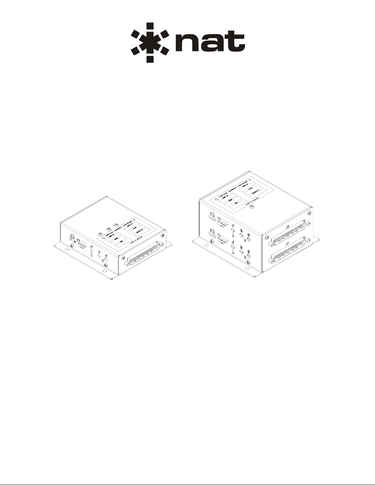
1.2 Product Description
The AA38-300 Local ICS Loop provides intercom functions for eight users with operation in HOT MIC or
VOX mode. A switch-selectable NAT or Andrea tie line allows connection to multi-unit systems and radio
or music can be connected at the AUX input.
The AA38-301 Local ICS Loop is functionally identical to the AA38-300 but has two fully independent
AA38-300 PCB assemblies mounted inside the enclosure and can therefore provide the same intercom
functions for sixteen users.
1.3 Design Features
The AA38-3xx Series remote bulkhead mounted units contain all the circuitry to support a wide variety of
ICS Loop applications, particularly isolation/ICS amplifier use, where the output is required to be headset
or line level.
The compact size and low weight of the AA38 allows mounting in restricted locations and the mapped
interconnect makes installation simple to carry out.
Built-in LED annunciators speed up airframe trouble-shooting by providing an indication of power to the
AA38 and VOX operation.
Level adjustments are provided for ICS level and AUX Input level.
1.4 Specifications
1.4.1 Electrical Specifications
Input Power
Input Voltage 27.5 Vdc, with reverse and over-voltage protection
32.2 Vdc max.
Input Current 0.66 Amps Max. @ 27.5 Vdc
Section 1 Rev: 1.00 Issue 4 Page 1-1
ENG-FORM: 800-0114.DOT
CONFIDENTIAL AND PROPRIETARY TO NORTHERN AIR BORNE TECHNOLOGY LTD.
Page 5

Input Signals
Quantity 8 Mic channels
(AA38-300) 1 ICS tie channel
1 Aux input channel
Quantity 16 Mic channels
(AA38-301) 2 ICS tie channels
2 Aux input channels
Audio Level 250 mVrms for mic inputs
0.34 Vrms for NAT ICS tie input
2.8 Vrms for Andrea ICS tie input
2.5 Vrms for Aux input
Impedance 150 Ω ±10% for mic inputs
1.6k Ω ±10% for NAT ICS tie input
250 Ω ±10% for Andrea tie input
940 Ω ±10% for Aux input
Circuitry Type All mics are single-ended inputs
Tie lines are single-ended inputs
Aux line is single-ended input
Better than -60 dB input-to-input crosstalk (Mic to Aux to ICS)
Output Signals
Quantity 8 Headset outputs
(AA38-300)
Quantity 16 Headset outputs
(AA38-301)
Rated Level Headset output 7.7V rms or 100 mW (20 dBm) into 600 Ω
Impedance 30 Ω ±10%. (Headset output)
Circuitry Type Balanced output for high common mode noise rejection
Audio Frequency Response
Intercom <3 dB from 350 Hz to 3000 Hz
RX <3 dB from 350 Hz to 6000 Hz
Distortion <10% THD @ Rated power output
Audio Noise Level >60 dB down from rated output (without signal)
Output Regulation <10% distortion / Δ3 dB max. of rated output power at 400% and
AA38-3xx Series Local ICS Loop
SM37 Installation and Operation Manual
75% of rated load
Section 1 Rev: 1.00 Issue 4 Page 1-2
ENG-FORM: 800-0114.DOT
CONFIDENTIAL AND PROPRIETARY TO NORTHERN AIR BORNE TECHNOLOGY LTD.
Page 6
AA38-3xx Series Local ICS Loop
SM37 Installation and Operation Manual
1.4.2 Physical Specifications
AA38-300 AA38-301
Height
Max.
Depth 4.60" (116.8 mm) max. including connector
Width 4.50" (114.3 mm) max. including flanges
Weight
Max.
Mounting Bulkhead mount with four 10-32 screws
Material/
Finish
Connectors Filtered male 37-pin D-subminiature.
connector with jack posts.
1.31"
(33.3 mm)
0.55 lbs
(0.25 Kg)
5052-H32 brushed aluminum with chromate conversion finish
Two filtered male 37-pin
D-subminiature. connector with
2.31”
(58.7 mm)
1.01 lbs
(0.45 Kg)
jack posts.
1.4.3 Environmental Specifications
Temperature -30 to +55°C (operating)
-55 to +85°C (survival)
Altitude 25,000 feet max.
Humidity 95%
Qualification of the AA38-300 Local ICS Loop was completed in accordance with
DO-160C Env. Cat. B4-CA[BMN]XXXXXXZBABBTZXXX.
Note: Refer to Environmental Qualification Form located in Section 2 of this Manual for complete details
of the environmental categories.
1.4.4 Product Approval
FAA: TSO-C50c (RTCA/DO-170 Class 1a)
Note: Applicable to AA38-300 and AA38-301 units serial number 3000 and up.
1.5 Unit Nomenclature
AA38-300 Intercom functions for eight users
Selectable NAT ICS or Andrea Tie Line
ICS volume, AUX volume and VOX controls
Live and VOX Intercom modes
VOX operation LED and 28 Vdc Power LED
Section 1 Rev: 1.00 Issue 4 Page 1-3
ENG-FORM: 800-0114.DOT
CONFIDENTIAL AND PROPRIETARY TO NORTHERN AIR BORNE TECHNOLOGY LTD.
Page 7

AA38-3xx Series Local ICS Loop
SM37 Installation and Operation Manual
AA38-301 Intercom functions for sixteen users
Selectable NAT ICS or Andrea Tie Lines
ICS volume, AUX volume and VOX controls
Live and VOX Intercom modes
VOX operation LED and 28 Vdc Power LED
Section 1 ends
Section 1 Rev: 1.00 Issue 4 Page 1-4
ENG-FORM: 800-0114.DOT
CONFIDENTIAL AND PROPRIETARY TO NORTHERN AIR BORNE TECHNOLOGY LTD.
Page 8

AA38-3xx Series Local ICS Loop
SM37 Installation and Operation Manual
Section 2 Installation
2.1 Introduction
Information in this section consists of unpacking and inspection procedures, installation procedure s, po stinstallation checks and installation drawings for the AA38-3xx Series Local ICS Loop.
Review all notes, warnings and cautions.
2.2 Unpacking and Inspection
Unpack the equipment carefully and locate the warranty card. Inspect the unit visually for damage due to
shipping and report all such claims immediately to the carrier involved. Check that all items listed below
are present before proceeding and report any shortage immediately to your supplier:
- Warranty Card
- Certificate of Conformity or Release Certification
2.2.1 Warranty
All Northern Airborne Technology Ltd. products are warranted for 2 years from date of installation by an
authorized NAT dealer, to be free of defects in workmanship or performance. This warranty covers all
materials and labour, but is exclusive of any transport to deliver the defective unit to and from NAT or its
designated warranty repair center, or any labour to remove or re-install the defective unit in the aircraft.
Contact NAT for any questions regarding this warranty, its applicability to your units and/or for return
authorization. NAT is the final arbitrator concerning warranty administration. Units which have been
physically damaged, burned, immersed in water or otherwise abused beyond the scope of normal use will
not be considered for warranty. WARRANTY IS VOID UNLESS THE PRODUCT IS INSTALLED BY AN
AUTHORIZED NAT DEALER. Product for which a warranty card is not returned shall be warranted from
date of manufacture.
2.3 Continued Airworthiness
Maintenance of the AA38-3xx Series Local ICS Loop is ‘on condition’ only. Periodic maintenance of this
product is not required.
Section 2 Rev: 1.00 Issue 4 Page 2-1
ENG-FORM: 805-0117.DOT
CONFIDENTIAL AND PROPRIETARY TO NORTHERN AIR BORNE TECHNOLOGY LTD.
Page 9

AA38-3xx Series Local ICS Loop
SM37 Installation and Operation Manual
2.4 Installation Procedures
2.4.1 Cautions
CAUTION:
In all installations, use shielded cable exactly as shown and ground as
indicated. Significant problems may result from not following these guidelines.
All audio installations can be seriously degraded by incorrect wiring and
shielding and may result in abnormal cross-talk, hum and ground-loop noise.
Be especially careful with all microphone wiring and tie line wiring, as these
lines carry the lowest level signals in the aircraft.
2.4.2 Cabling and Wiring
All wire shall be selected in accordance with the original aircraft manufacturer's Maintenance Instructions
or AC43.13-1B Change 1, Paragraphs 11-76 through 11-78. Unshielded wire types shall qualify to
MIL-W-22759 as specified in AC43.13-1B Change 1, Paragraphs 11-85, 11-86, and listed in Table 11-11.
For shielded wire applications, use Tefzel MIL-C-27500 shielded wire with solde r sleeve s (fo r shield
terminations) to make the most compact and easily terminated interconnect. Follow the connector map in
Section 2.7 as required.
Allow 3" from the end of the shielded wiring to the shield termination to allow the connector hood to be
easily installed. Reference the interconnect drawing in Section 2.7 for shield termination details. Note that
the hood is a "clamshell" hood, and is installed after the wiring is complete. Aircraft harnessing shall
permit the unit to be lowered from the panel for easy access to all side adjustments. Do NOT mount the
unit until all adjustments have been performed.
Maintain wire segregation and route wiring in accordance with the original aircraft manufacturers
Maintenance Instructions.
Unless otherwise noted, all wiring shall be a minimum of 22 AWG, except power and ground lines, which
shall be a minimum of 20 AWG. Reference the Interconnect drawing for additional specifications. Check
that the ground connection is clean and well secured, and that it shares no path with any electrically noisy
aircraft accessories such as blowers, turn and bank instruments or similar loads. Power to this unit must
be supplied from a separate circuit breaker or fuse (fast blow), and not attached to any other circuit
breaker without additional protection. Verify that the selected circuit breaker size and wire gauge are
adequate for the installation using the techniques specified in AC43.13-1B Change 1, Paragraphs 11-47
through 11-51 and 11-66 through 11-69.
2.4.3 Installation Options
The AA38-300 can be configured for up to three NAT Tie Lines, or one Andrea Tie Line and each
‘section’ of the AA38-301 can be configured separately for these options.
The switches that determine the installation configuration are ICS GAIN switches 1, 2, 3, and 4, and ICS
MODE switches C1/C2 and C3/C4, accessible through the left hand side of the unit. Refer to Figures 1, 2
and 3 to determine the proper switch settings.
Section 2 Rev: 1.00 Issue 4 Page 2-2
ENG-FORM: 805-0117.DOT
CONFIDENTIAL AND PROPRIETARY TO NORTHERN AIR BORNE TECHNOLOGY LTD.
Page 10

AA38-3xx Series Local ICS Loop
SM37 Installation and Operation Manual
Figure 1: Switch Configurations
The rocker switches used to configure the AA38 for the appropriate tie line option are visible through the
ICS MODE opening(s) in the side of the unit. The diagrams below show one set of rocker switches for the
AA38-300 and two for the AA38-301.
OR
Figure 2: ICS MODE Switch positions for
1, 2, or 3 NAT ICS Tie Lines
Mode Switch Positions
1 NAT ICS Tie Line ICS GAIN switch #1 DOWN, ICS GAIN switches # 2, 3, and 4 UP
ICS MODE switch: C1/C2 to C2 and C3/C4 to C4 (See figure 2)
2 NAT ICS Tie Lines ICS GAIN switch #2 DOWN, ICS GAIN switches # 1, 3, and 4 UP
ICS MODE switch: C1/C2 to C2 and C3/C4 to C4 (See figure 2)
3 NAT ICS Tie Lines ICS GAIN switch #3 DOWN, ICS GAIN switches # 1, 2, and 4 UP
ICS MODE switch: C1/C2 to C2 and C3/C4 to C4 (See figure 2)
ANDREA Tie Lines ICS GAIN switch #4 DOWN, ICS GAIN switches # 1, 2, and 3 UP
ICS MODE switch: C1/C2 to C1 and C3/C4 to C3 (See figure 3)
Table 1
Mode and Switch Positions
Figure 3: ICS MODE Switch Positions
for ANDREA Tie Lines
Section 2 Rev: 1.00 Issue 4 Page 2-3
ENG-FORM: 805-0117.DOT
CONFIDENTIAL AND PROPRIETARY TO NORTHERN AIR BORNE TECHNOLOGY LTD.
Page 11

AA38-3xx Series Local ICS Loop
SM37 Installation and Operation Manual
2.4.4 Post-Installation Checks
2.4.4.1 Voltage/Resistance Checks
Do not attach the AA38-3xx until the following conditions are met.
Check the following for the AA38-300:
a) Check P101 pin 1 for +28 Vdc relative to ground.
b) Check P101 pin 20 for continuity to ground (less than 0.5Ω).
Check the following for the AA38-301:
a) Check P1 and P2 pin 1 for +28 Vdc relative to ground.
b) Check P1 and P2 pin 20 for continuity to ground (less than 0.5Ω).
2.4.4.2 Power On Checks
Power up the aircraft’s systems and confirm normal operation of all functions of the AA38-3xx. Refer to
Section 3 (Operation) for specific operational details.
a) Check for correct radio audio and adjust for acceptable level.
b) Run through all installed functions and check the ICS functions for all users.
c) Check preset adjustments are completed before aircraft departure. Refer to Section 2.5 for
details of adjustments.
Notes: 1) Significantly different headsets may have different mic characteristics.
2) The David Clark M-7 mic is much more active than their M-4 or M-1 microphones and may
aggravate headset imbalance if used in a mixed system.
Upon satisfactory completion of all performance checks, make all required log book entries, electrical
load, weight and balance amendments and other documentation as required by your local regulatory
agency before releasing the aircraft for service.
2.5 Adjustments and Connections
The unit is shipped from the factory with all internal adjustments set to the normal test levels. Once
installed in the aircraft, it may be desirable to change some of these settings to best suit the local
operating environment. The internal adjustments are located along the right side of the unit.
2.5.1 Audio Levels
Adjust ICS VOL and AUX VOL to desired levels. Clockwise rotation of these controls will increase audio
volume level.
Setting the ICS VOX control fully clockwise sets the AA38 to ‘live’ mode. Adjusting it counter clockwise
sets the level which activates the VOX mode.
Section 2 Rev: 1.00 Issue 4 Page 2-4
ENG-FORM: 805-0117.DOT
CONFIDENTIAL AND PROPRIETARY TO NORTHERN AIR BORNE TECHNOLOGY LTD.
Page 12

AA38-3xx Series Local ICS Loop
SM37 Installation and Operation Manual
2.6 Accessories Required But Not Supplied
Installation kit p/n AA38-IKC (crimp) is required to complete the installation.
AA38-IKC consists of
Quantity Description NAT Part No.
1 D-min 37 Socket Housing 20-21-037
37 MS Crimp Socket 20-26-901
1* Jack Screw Set 20-27-002
1* Lock Clip Set 20-27-004
1 37 Pin Connector Hood 20-29-038
* Use as required.
Note: Two kits will be required for the AA38-301.
2.7 Installation Drawings
DOCUMENT REV. DESCRIPTION TYPE SERIAL NO.
AA38-300
AA38\300\403-0 1.00 Local ICS Loop Interconnect 1622 and up
AA38\300\405-0 1.00 Local ICS Loop Connector Map 1622 and up
AA38\300\521-0 1.02 Local ICS Loop Environmental Qualification Form 3000 and up
AA38\300\922-0 1.00 Local ICS Loop Mechanical Installation 1622 to 2999
AA38\300\922-0 1.10 Local ICS Loop Mechanical Installation 3000 to 3284
AA38\300\922-0 1.20 Local ICS Loop Mechanical Installation 3825 and up
AA38-301
AA38\301\403-0 1.00 16 Place Local ICS Loop Interconnect 2067 and up
AA38\301\403-1 1.00 16 Place Local ICS Loop Interconnect 2067 and up
AA38\301\405-0 1.00 16 Place Local ICS Loop Connector Map 2067 and up
AA38\301\922-0 1.02 16 Place Local ICS Loop Mechanical Installation 2067 and up
Section 2 ends following the above documents
Section 2 Rev: 1.00 Issue 4 Page 2-5
ENG-FORM: 805-0117.DOT
CONFIDENTIAL AND PROPRIETARY TO NORTHERN AIR BORNE TECHNOLOGY LTD.
Page 13

Confidential and Proprietary to NAT
Page 14

Confidential and Proprietary to NAT
Page 15

Page 16

Page 17

Page 18

Confidential and Proprietary to NAT
Page 19

Page 20

Page 21

Page 22

Page 23

Page 24

Page 25

AA38-3xx Series Local ICS Loop
SM37 Installation and Operation Manual
Section 3 Operation
3.1 Introduction
Information in this section consists of functional and operational procedures for the AA38-3xx Series
Local ICS Loop.
3.2 General Information
The AA38-300 provides intercom functions for eight users (sixteen for the AA38-301) with operation in
HOT MIC or VOX mode. A switch-selectable NAT or Andrea tie line allows connection to multi-unit
systems and an AUX input allows radio or music to be connected to the AA38.
3.3 Controls and Indicators
The AA38-3xx Local ICS Loop has no normal user operational aspects. During installation, or if the unit
has been exchanged, it may be a requirement to change internal adjustments. This should be done o nly
by fully qualified personnel.
Section 3 ends
Section 3 Rev: 1.00 Issue 4 Page 3-1
ENG-FORM: 806-0112.DOT
CONFIDENTIAL AND PROPRIETARY TO NORTHERN AIR BORNE TECHNOLOGY LTD.
 Loading...