

Page 1
SM39
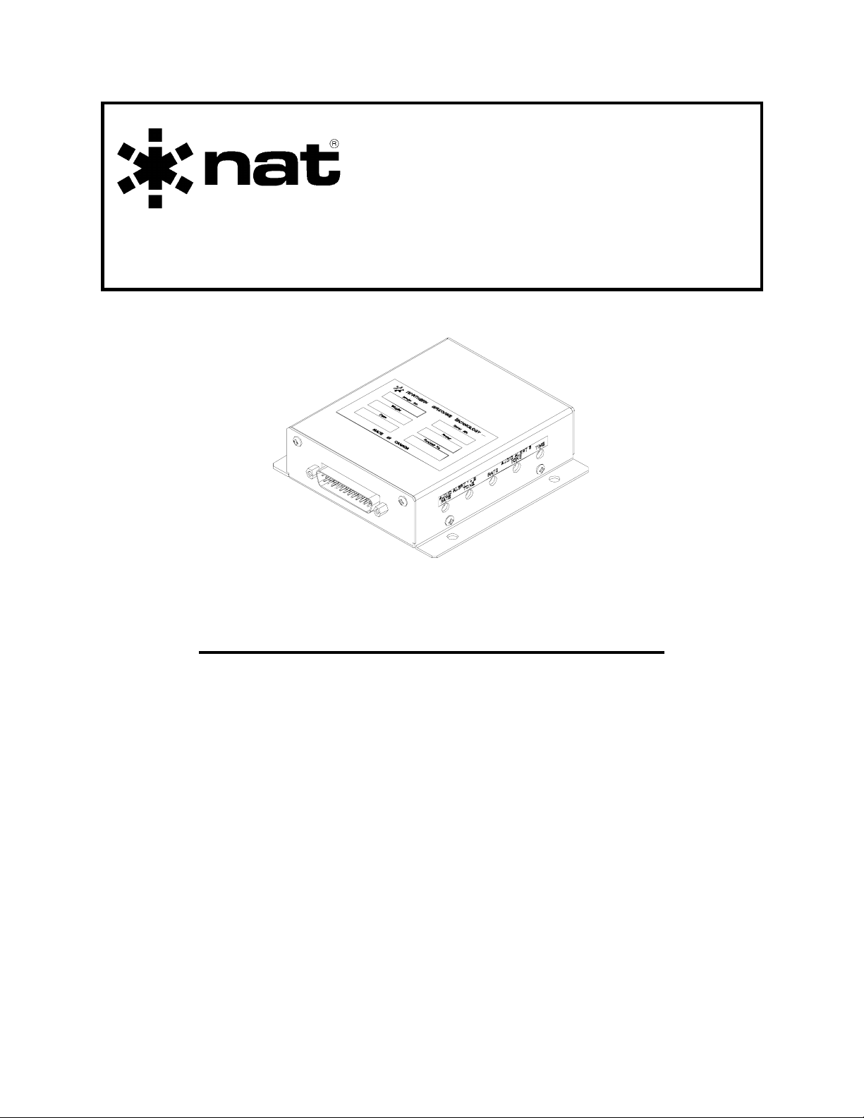
AA37 Series
Alerting System
INSTALLATION AND OPERATION MANUAL
REV 4.00 November 10, 2003
Northern Airborne Technology Ltd.
1925 Kirschner Road
Kelowna BC, Canada
V1Y 4N7
Telephone (250) 763-2232
Facsimile (250) 762-3374
Copyright 2003 by Northern Airborne Technology
CONFIDENTIAL AND PROPRIETARY TO NORTHERN AIRBORNE TECHNOLOGY LTD.
Page 2

Page 3

SM39 Rev. 4.00 AA37 Series Alerting System Manual
Periodically NAT will release manual amendments. In order to maintain the most
accurate and up to date manual these amendments should be carried out immediately
upon receipt and recorded on the following amendment record.
AMENDMENT RECORD
Amendment
Number
Amendment
Date
Section(s)
Changed
Date
Entered
Entered By
Insert any Amendment Instruction sheets after this page.
Nov 10, 2003 Page ii
ENG-FORM: 820-0109.DOT
CONFIDENTIAL AND PROPRIETARY TO NORTHERN AIRBORNE TECHNOLOGY LTD.
Page 4

Page 5

SM39 Rev. 4.00 AA37 Series Alerting System Manual
Table of Contents
Section Title Page
1.0 Description
1.1 Introduction 1-1
1.2 Purpose of Equipment 1-1
1.3 Features 1-1
1.4 Specifications 1-1
1.4.1 Electrical Specifications 1-1
1.4.2 Physical Specifications 1-2
1.4.3 Environmental Specifications 1-3
1.5 Unit Nomenclature 1-3
2.0 Installation
2.1 Introduction 2-1
2.2 Unpacking and Inspection 2-1
2.3 Installation Procedures 2-1
2.3.1 Warnings 2-1
2.3.2 Cautions 2-1
2.3.3 Cabling and Wiring 2-2
2.3.4 Post-Installation Checks 2-2
2.4 Installation Drawings 2-4
3.0 Operation
3.1 Introduction 3-1
3.2 General 3-1
3.3 Configuration 3-1
Nov 10, 2003 Page iii
ENG-FORM: 820-0109.DOT
CONFIDENTIAL AND PROPRIETARY TO NORTHERN AIRBORNE TECHNOLOGY LTD.
Page 6

Page 7

SM39 Rev. 4.00 AA37 Series Alerting System Manual
Section 1.0 Description
1.1 Introduction
This manual contains information on the AA37 series Alerting Systems.
Information in this section consists of purpose of equipment, features and specifications.
1.2 Purpose of Equipment
The AA37 series are dual channel Alerting Systems that provide two or three level
alerting.
1.3 Features
The AA37 Alerting Systems are compact, remote mounted units. All outputs are fully
isolated to allow installation in dual audio controller systems. Trigger inputs can be
active low or active high dependent on the model, allowing easy interface to common
aircraft systems. The tone and rate of the alerts are adjustable to allow tailoring of the
tones to ensure they do not interfere with existing airframe warning functions.
1.4 Specifications
1.4.1 Electrical Specifications
Input Power 27.5 Vdc at 200 mA (nominal)
Input Signals
Alert 1
AA37-001 2 active low triggers, 30 mA max.
AA37-002 2 active high triggers, 30 mA max.
AA37-212 2 active low triggers, 30 mA max.
Alert 2 (all models) 2 active low triggers, 30 mA max.
Alert 3 (AA37-212 only) 2 active low triggers, 3 mA max.
Nov 10, 2003 Page 1-1
ENG-FORM: 800-0103.DOT
Page 8

AA37 Series Alerting System Manual SM39 Rev. 4.00
Output Signals 2 headset outputs
Output Level into 600 Ω
100% 30 mW
50% 15 mW
33% 10 mW
Output Level into 150 Ω
100% 11 mW
50% 6 mW
33% 4 mW
Output Impedance
100% output 900 Ω ±10%
50% output 1.6 kΩ ±10%
33% output 2.1 kΩ ±10%
Tone Frequency
Alert 1 & 2 Adjustable tone from 750 Hz to 2.3 kHz.
Alert 2 Adjustable rate from 1 Hz to 20 Hz.
Alert 3 (AA37-212 only) Adjustable tone and rate as above with
duration of 1 to 3 seconds.
Audio Noise Level > 60 dB down from rated output.
Crosstalk < -60 dB output to output.
1.4.2 Physical Specifications
Height 31.7 mm (1.25 inches)
Length 111.7 mm (4.4 inches)
Width 114.3 mm (4.5 inches)
Weight
AA37-001 and -002 220 g (0.49 lb)
AA37-212 230 g (0.51 lb)
Mounting Bulkhead mount with four 10-32 screws.
Page 1-2 Nov 10, 2003
ENG-FORM: 800-0103.DOT
Page 9

SM39 Rev. 4.00 AA37 Series Alerting System Manual
Material/Finish Chassis & cover are 5052-H32 brushed
aluminium with chromate conversion
finish.
Connectors 25 pin Male D-subminiature connector
with jack posts
1.4.3 Environmental Specifications
Temperature
Operating -20 C to +55 C
Survival -55 C to +85 C
Altitude 25,000 ft
Humidity 95%
1.5 Unit Nomenclature
Model Description / Distinction
AA37-212 Dual channel, 3 level alerting.
Provides alerting for AA94/AMS42/44.
Floating outputs, 150 - 600 Ω loads.
Low level triggers.
AA37-001 Dual channel, 2 level alerting.
Audible output tones for ICS call or alerting.
Floating outputs, 150 - 600 Ω loads.
Low level triggers.
AA37-002 Dual channel, 2 level alerting.
Audible output tones for ICS call or alerting.
Floating outputs, 150 - 600 Ω loads.
High level triggers for Alert #1.
Low level triggers for Alert #2.
End of section 1.0
Nov 10, 2003 Page 1-3
ENG-FORM: 800-0103.DOT
Page 10

Page 11

SM39 Rev. 4.00 AA37 Series Alerting System Manual
Section 2.0 Installation
2.1 Introduction
Information in this section consists of: unpacking and inspection procedures, installation
procedures, post-installation checks, and installation drawings.
2.2 Unpacking and Inspection
Unpack the equipment carefully and locate the warranty card. Inspect the unit visually
for damage due to shipping and report all such claims immediately to the carrier
involved. Note that each unit should have the following:
- AA37 Dual Channel Alerting System
- Warranty Card
- Release Certification
Verify that all items are present before proceeding and report any shortage immediately
to your supplier.
Complete the warranty card information and send it to NAT when the installation is
complete. If you fail to complete the warranty card, the warranty will be activated on
date of shipment from NAT.
2.3 Installation Procedures
2.3.1 Warnings
Do not bundle any lines from this unit with transmitter coax lines, or AM audio
rectification may result. Do not bundle any input or output audio, or DC power lines
from this unit with 400 Hz synchro wiring or AC power lines. Do not position this unit or
wiring from this unit next to any device with a strong alternating magnetic field such as
an inverter, or significant audio interference will result.
2.3.2 Cautions
In all installations, use shielded cable exactly as shown and ground as indicated.
Significant problems may result from not following these guidelines, especially with
regard to ground loop noise.
Nov 10, 2003 Page 2-1
ENG-FORM: 805-0106.DOT
CONFIDENTIAL AND PROPRIETARY TO NORTHERN AIRBORNE TECHNOLOGY LTD.
Page 12

AA37 Series Alerting System Manual SM39 Rev 4.00
2.3.3 Cabling and Wiring
For shielded wire applications, use Tefzel Mil-M-27500 or Mil-M-81044 shielded wire
with solder sleeves (for shield terminations) to make the most compact and easy to
terminate interconnect. Follow the wiring diagrams in Section 2.4 as required.
Allow 3 inches from the end of the wire to the shield termination to allow the hood to be
easily installed. Note that the hood is a “clamshell” hood, and is installed after the
wiring is complete.
All wiring should be at least 22 AWG. Ensure that all ground connections are clean and
well secured.
2.3.4 Post-Installation Checks
2.3.4.1 Voltage/resistance checks
Do not attach the AA37 until the following conditions are met.
Check the following:
a) P101 pin <1> for +28 Vdc relative to ground.
b) P101 pin <14> for continuity to ground (below 0.5 Ω).
2.3.4.2. Alert 1
a) Install the AA37. Power up the ship’s systems. Connect a headset to the pilot’s
headset jack and activate the AA37 Alert 1 trigger circuit. There should be a
continuous tone with no unusual noises or disruptions heard in the headset.
Reset the AA37 Alert 1 trigger circuit.
b) Activate the second AA37 Alert 1 trigger circuit, if installed. There should be a
continuous tone with no unusual noises or disruptions heard in the headset.
Reset the AA37 Alert 1 trigger circuit.
c) Repeat steps 2.3.4.2 a) and b) for the copilot’s headset, if the feature is used in
the installation.
Page 2-2 Nov 10, 2003
ENG-FORM: 805-0106.DOT
CONFIDENTIAL AND PROPRIETARY TO NORTHERN AIRBORNE TECHNOLOGY LTD.
Page 13

SM39 Rev. 4.00 AA37 Series Alerting System Manual
2.3.4.5 Alert 2
a) Activate the AA37 Alert 2 trigger circuit. There should be an intermittent (hi/lo)
tone with no unusual noises or disruptions heard in the headset. Reset the AA37
Alert 2 trigger circuit.
b) Activate the second AA37 Alert 2 trigger circuit, if installed. There should be an
intermittent (hi/lo) tone with no unusual noises or disruptions heard in the
headset. Reset the AA37 Alert 2 trigger circuit.
c) Repeat steps 2.3.4.5 a) and b) for the copilot’s headset, if the feature is used in
the installation.
2.3.4.6 Alert 3 (AA37-212 only)
a) Activate the AA37 Alert 3 trigger circuit. There should be a swept tone of 1 to 3
seconds duration, with no unusual noises or disruptions heard in the headset.
Reset the AA37 Alert 3 trigger circuit.
b) Activate the second AA37 Alert 3 trigger circuit, if installed. There should be a
swept tone of 1 to 3 seconds duration, with no unusual noises or disruptions
heard in the headset. Reset the AA37 Alert 3 trigger circuit.
c) Repeat steps 2.3.4.6 a) and b) for the copilot’s headset, if the feature is used in
the installation.
2.4 Installation Drawings
DRAWING REV. DESCRIPTION TYPE
AA37\212\403-0 1.02 Alerting System Interconnect
AA37\212\405-0 1.01 Alerting System Connector Map
AA37\212\922-0 1.00 Alerting System Mechanical
AA37\001\403-0 1.01 Alerting System Interconnect
AA37\001\405-0 1.00 Alerting System Connector Map
AA37\001\922-0 1.00 Alerting System Mechanical
Nov 10, 2003 Page 2-3
ENG-FORM: 805-0106.DOT
CONFIDENTIAL AND PROPRIETARY TO NORTHERN AIRBORNE TECHNOLOGY LTD.
Page 14

AA37 Series Alerting System Manual SM39 Rev 4.00
AA37\002\403-0 1.01 Alerting System Interconnect
AA37\002\405-0 1.00 Alerting System Connector Map
Section 2.0 ends after these drawings
Page 2-4 Nov 10, 2003
ENG-FORM: 805-0106.DOT
CONFIDENTIAL AND PROPRIETARY TO NORTHERN AIRBORNE TECHNOLOGY LTD.
Page 15

Confidential and Proprietary to NAT
Page 16

Page 17

Confidential and Proprietary to NAT
Page 18

Page 19

Confidential and Proprietary to NAT
Page 20

Page 21

Confidential and Proprietary to NAT
Page 22

Page 23

Confidential and Proprietary to NAT
Page 24

Page 25

Confidential and Proprietary to NAT
Page 26

Page 27

Confidential and Proprietary to NAT
Page 28

Page 29

Confidential and Proprietary to NAT
Page 30

Page 31

SM39 Rev. 4.00 AA37 Series Alerting System Manual
Section 3.0 Operation
3.1 Introduction
Information in this section consists of the functional and operational procedures for the
AA37 series Alerting Systems.
3.2 General
The AA37 series are dual channel Alerting Systems that provide two or three level
alerting.
3.3 Configuration
The AA37 has no normal user operational aspects. During installation, or if the unit
has been exchanged, it may be a requirement to change internal adjustments. This
should be done ONLY BY FULLY QUALIFIED PERSONNEL.
End of section 3.0
Nov 10, 2003 Page 3-1
ENG-FORM: 806-0106.DOT
CONFIDENTIAL AND PROPRIETARY TO NORTHERN AIRBORNE TECHNOLOGY LTD.
Page 32

 Loading...