

Page 1
SM58
AA36-100
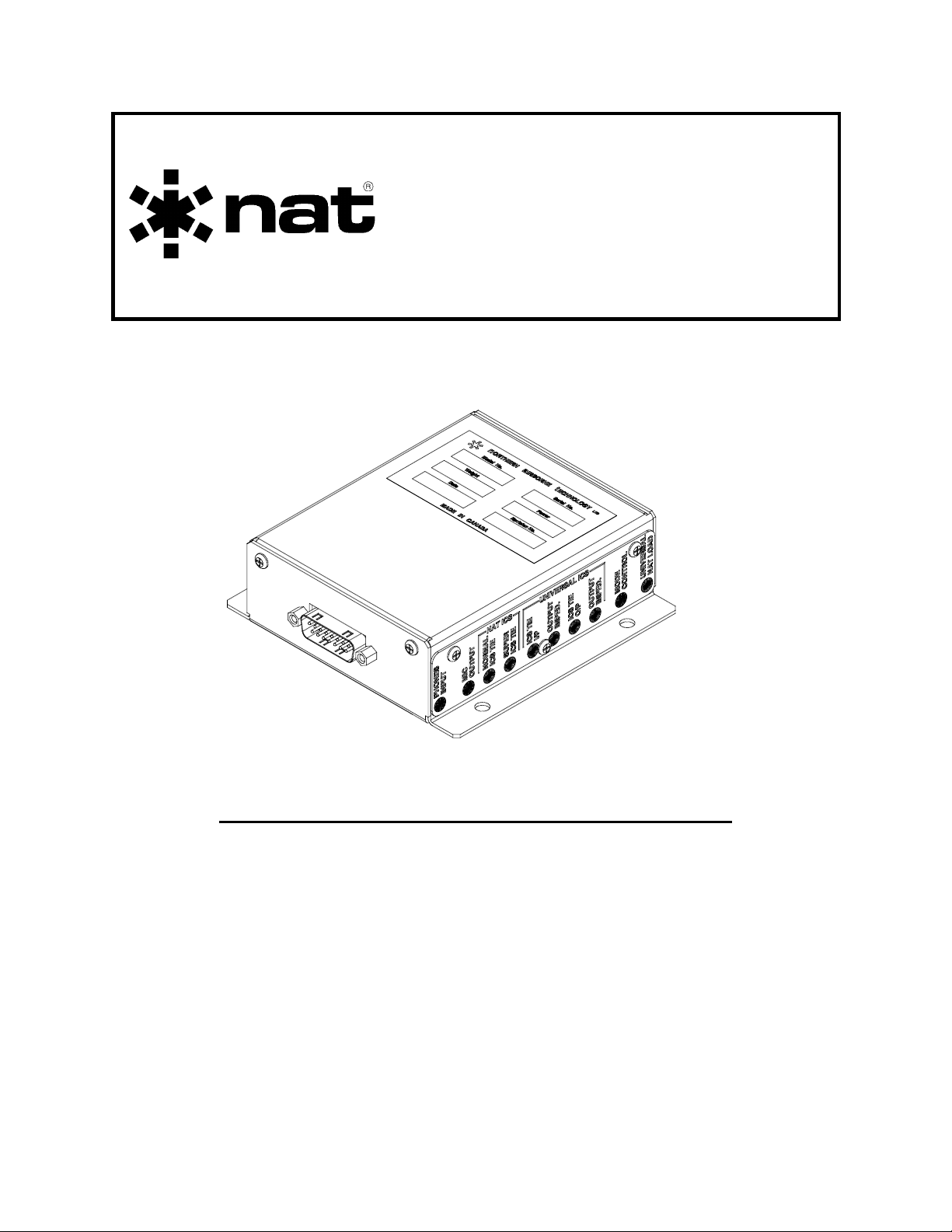
Digital ICS Tie Line Adapter
INSTALLATION AND OPERATION MANUAL
REV 4.00 November 14, 2003
Northern Airborne Technology Ltd.
1925 Kirschner Road
Kelowna BC, Canada.
V1Y 4N7
Telephone (250) 763-2232
Facsimile (250) 762-3374
Copyright 2003 by Northern Airborne Technology
CONFIDENTIAL AND PROPRIETARY TO NORTHERN AIRBORNE TECHNOLOGY LTD.
Page 2

Page 3

SM58 Rev. 4.00 AA36-100 Digital ICS Tie Line Adapter Manual
Performed at factory
Periodically NAT will release manual amendments. In order to maintain the most
accurate and up to date manual these amendments should be carried out immediately
upon receipt and recorded on the following amendment record.
AMENDMENT RECORD
Amendment
Number
Amendment
Date
Section(s)
Changed
Date
Entered
Entered By
1 Mar 13/07 2
Insert any Amendment Instruction sheets after this page.
Nov 14, 2003 Page ii
ENG-FORM: 820-0109.DOT
CONFIDENTIAL AND PROPRIETARY TO NORTHERN AIRBORNE TECHNOLOGY LTD.
Page 4

Page 5
INSTALL_OPS
MANUAL AMENDMENT
Manual: SM58 (AA36-100) Amendment #: 1
Document # SM58\Install_Ops\809-0001) Amendment Date: Mar 13, 2007
The purpose of this amendment is to correct the installation information.
Amendment Instructions:
1
2-5 and 2-6 Rev 4.00 2-5 and 2-6 Rev 4.00 Amendment 1
Note: Ensure that all drawings are inserted in the order shown on the latest drawing lists.
2 Update the Amendment Record sheet at the front of the manual.
3 Insert this page into the manual after the Amendment Record sheet (page ii).
Manual Amendment ends after the following amended pages
Remove Pages Replace With Pages
Amendment # 1 Mar 13, 2007 Page 1
ENG-FORM: 809-0109.DOT
CONFIDENTIAL AND PROPRIETARY TO NORTHERN AIRBORNE TECHNOLOGY LTD.
Page 6

Page 7

SM58 Rev. 4.00 AA36-100 Digital ICS Tie Line Adapter Manual
Table of Contents
Section Title Page
1.0 Description
1.1 Introduction 1-1
1.2 Purpose of Equipment 1-1
1.3 Features 1-1
1.4 Specifications 1-2
1.4.1 Electrical Specifications 1-2
1.4.2 Physical Specifications 1-3
1.4.3 Environmental Specifications 1-3
1.5 Unit Nomenclature 1-3
2.0 Installation
2.1 Introduction 2-1
2.2 Unpacking and Inspection 2-1
2.2.1 Warranty 2-1
2.3 Installation Procedures 2-1
2.3.1 Warnings 2-1
2.3.2 Cautions 2-2
2.3.3 Cabling and Wiring 2-2
2.3.4 Installation Options 2-3
2.3.5 Adjustments 2-3
2.3.6 Mechanical Installation 2-5
2.3.7 Post-Installation Checks 2-5
2.4 Continued Airworthiness 2-6
2.5 Accessories Required 2-6
2.6 Installation Drawings 2-6
3.0 Operation
3.1 Introduction 3-1
3.2 General 3-1
3.3 Operation 3-1
Nov 14, 2003 Page iii
ENG-FORM: 820-0109.DOT
CONFIDENTIAL AND PROPRIETARY TO NORTHERN AIRBORNE TECHNOLOGY LTD.
Page 8

Page 9

SM58 Rev. 4.00 AA36-100 Digital ICS Tie Line Adapter Manual
Section 1.0 Description
1.1 Introduction
This manual contains information on the AA36-100 Digital ICS Tie Line Adapter.
Information in this section consists of purpose of equipment, features and specifications,
and unit nomenclature.
1.2 Purpose of Equipment
The AA36-100 will allow any NAT audio intercom product with an ICS tie line or
SuperNAT tie line to be interfaced to other proprietary bi-directional and uni-directional
ICS tie lines.
Typically, the AA36-100 is used to add NAT intercom/audio systems to an existing
system that is not manufactured by NAT.
The AA36-100 can be set to work in a number of installation configurations. The typical
application would have an NAT ICS tie line (or SuperNAT tie line) being interfaced to
another ‘universal’ bi-directional tie line (e.g. dB Systems, Gemelli, Andrea, etc).
Alternatively, the NAT tie line can be interfaced with the ‘universal’ uni-directional tie line
(e.g. mic and phones).
1.3 Features
The AA36-100 is designed to be easy to install and set up.
The AA36-100 accepts intercom bi-directional audio from the NAT standard ICS tie line
(340 mVrms into 2 kOhms), and can accommodate up to three NAT loads in parallel. In
Nat Super tie mode (1.2 Vrms into 2 kOhms), up to 3 Nat Super tie loads are allowed.
At installation or service, the following functions can be adjusted to suit the user:
• the universal microphone output levels (but not impedances)
• the universal bi-directional ICS tie line output levels and impedances
• the attenuation of the analog audio signal arriving on the universal ICS tie line or
microphone input
• the attenuation of the analog audio signal arriving on the NAT ICS tie line
• the output level of the NAT bi-directional ICS tie line
• the universal bi-directional tie line can be configured to one of 4 possible proprietary
tie lines
On power up, a burst of white noise is generated on each bi-directional ICS tie line,
along with a short tie line identification message.
Nov 14, 2003 Page 1-1
ENG-FORM: 800-0106.DOT
CONFIDENTIAL AND PROPRIETARY TO NORTHERN AIRBORNE TECHNOLOGY LTD.
Page 10

AA36-100 Digital ICS Tie Line Adapter Manual SM57 Rev. 4.00
1.4 Specifications
1.4.1 Electrical Specifications
Power Supply Multiple switchers and linear regulators with
reverse and over voltage protection. Short
Input Power +27.5 Vdc at 0.3 A max.
circuit protected by internal fuse.
Input Signals
Quantity: 1 phones channel.
Rated Level: 0.5 V to 8.5 Vrms (10 discrete levels).
Impedance: 600 ohms ±10%.
Circuitry Type: Balanced input.
Output Signals
Quantity: 1 mic output.
Rated Level: 0.25 V to 2.8 Vrms into 150 Ω (10 discrete levels).
Circuitry Type: Balanced output.
Bi-directional Signals (2)
Rated Levels:
NAT ICS Tie Line: 340 mVrms ±10% into 2000 Ω ±10% (1 load)
227 mVrms ±10% into 1000 Ω ±10% (2 loads)
170 mVrms ±10% into 667 Ω ±10% (3 loads)
Super NAT ICS Tie Line: 1.2 Vrms ±10% into 2000 Ω ±10% (1 load)
1.2 Vrms ±10% into 1000 Ω ±10% (2 loads)
1.2 Vrms ±10% into 667 Ω ±10% (3 loads)
Universal Bi-directional ICS Tie Line:
dB Systems 355-003 0.8 Vrms ±10% into 300 Ω ±10%
Gemelli AG-06-1U5 1.4 Vrms ±10% into 6800 Ω ±10%
Andrea A301A-6W 2.8 Vrms ±10% into 600 Ω ±10%
Circuitry Type: Balanced circuitry.
NAT ICS Tie Line input impedance: 2000 Ω ±10%.
NAT AA95-xxx 340 mVrms ±10% into 2 kΩ ±10%
Universal ICS Tie Line input impedance:
dB Systems 355-003 300 Ω ±10%
Gemelli AG-06-1U5 6800 Ω ±10%
Andrea A301-6W 225 Ω ±10%
Audio Frequency Response: ≤3 dB from 350 to 6000 Hz
Distortion: ≤1% THD at rated output
NAT AA95-xxx 2000 Ω ±10%
Audio Noise Level without Signal: ≤-60 dB from rated output
Page 1-2 Nov 14, 2003
ENG-FORM: 800-0106.DOT
CONFIDENTIAL AND PROPRIETARY TO NORTHERN AIRBORNE TECHNOLOGY LTD.
Page 11

SM58 Rev. 4.00 AA36-100 Digital ICS Tie Line Adapter Manual
1.4.2 Physical Specifications
Height 1.40” (35.6 mm) max
Depth 4.59” (116.6 mm) max (not including connector)
Width 4.54” (115.3 mm) max
Weight 0.59 lb. (0.27 kg)
Mounting Bulk head x 4 mounting holes 0.21” (5.4mm) diam
Material/Finish Brushed aluminum with chromate conversion
Connectors One 15 pin male filtered D-min connector with
jackposts
1.4.3 Environmental Specifications
Temperature:
Operating -20° C to +55° C
Altitude 50,000 ft
Humidity 95%
Survival -55° C to +85° C
Shock: Operational 6 g
Crash Safety 15 g
DO-160D Env. Cat. [(A1)(D1)]-XXB[(SBM)(UF)]XXXXXXXXXXX[UUX]MXXXX.
1.5 Unit Nomenclature
Model Description / Distinction
AA36-100 2 Bi-directional ICS tie lines
1 Microphone output
1 Phone input
End of section 1.0
Nov 14, 2003 Page 1-3
ENG-FORM: 800-0106.DOT
CONFIDENTIAL AND PROPRIETARY TO NORTHERN AIRBORNE TECHNOLOGY LTD.
Page 12

Page 13

SM58 Rev. 4.00 AA36-100 Digital ICS Tie Line Adapter Manual
Section 2.0 Installation
2.1 Introduction
Information in this section consists of: unpacking and inspection procedures, installation
procedures, post-installation checks, and installation drawings.
2.2 Unpacking and Inspection
Unpack the equipment carefully and locate the warranty card. Inspect the unit visually
for damage due to shipping and report all such claims immediately to the carrier
involved. Note that each unit should have the following:
- AA36-100 Digital ICS Tie Line Adapter
- Install Kit (with metal ‘hood’)
- Warranty Card
- Release certification
Verify that all items are present before proceeding and report any shortage immediately
to your supplier.
2.2.1 Warranty
Complete the warranty card information and send it to NAT when the installation is
complete. If you fail to complete the warranty card, the warranty will be activated on
date of shipment from NAT.
Note: An appropriately rated facility, e.g. Certified Aircraft Repair Station, must install
this equipment in accordance with applicable regulations. NAT Ltd’s warranty is
not valid unless the equipment is installed by an authorized NAT Dealer. Failure
to follow any of the installation instructions, or installation by a non-certified
individual or agency will void the warranty, and may result in a non-airworthy
installation.
2.3 Installation Procedures
2.3.1 Warnings
Do not bundle any lines from this unit with transmitter coax lines. Do not bundle any
audio or DC power lines from this unit with 400 Hz synchro wiring or AC power lines. Do
not position this unit or wiring from this unit next to any device with a strong alternating
magnetic field such as an inverter, or significant audio interference will result.
Nov 14, 2003 Page 2-1
ENG-FORM: 805-0104.DOT
PROPRIETARY AND CONFIDENTIAL TO NORTHERN AIRBORNE TECHNOLOGY LTD.
Page 14

AA36-100 Digital ICS Tie Line Adapter Manual SM58 Rev. 4.00
A
2.3.2 Cautions
⇒ In all installations, use shielded cable exactly as shown and ground as indicated.
Significant ground loop and noise problems may result from not following these
guidelines. Ensure chassis is grounded to provide proper shield terminations.
⇒ Use caution when routing microphone wiring, as it carries low-level signals prone
to coupling from other sources.
⇒ Do not take a ground from the instrument panel or similar location that shares a
ground return with a turn and bank, horizon or other motor driven instrument.
This may cause the unit to pick up the sound of the motor as ground loop
interference.
2.3.3 Cabling and Wiring
All unshielded wire should be Tefzel MIL-M-22759 or equivalent. For shielded wire
applications, use Tefzel MIL-C-27500 shielded wire with solder sleeves (for shield
terminations) to make the most compact and easily terminated interconnect. Follow the
wiring diagrams in Section 2.6 as required.
Utilizing solder sleeves, create up to 3
shield pigtails in the wiring harness, as
shown in the Interconnect Diagram
(AA36\100\403-0, Rev 1.00 or higher).
Each pigtail should be no more than
3.0” long.
Note: The hood is a ‘two-piece’ unit,
and is assembled after the wiring
Metal
Hood
is complete.
ll wiring should be at least 24 AWG,
Solder
Sleeves
except power and ground lines, which
should be at least 20 AWG. Ensure
that all ground connections are clean
and well secured.
To prevent system failure or inadequate equipment protection, supply power from a
dedicated 1.0 A circuit breaker.
Page 2-2 Nov 14, 2003
ENG-FORM: 805-0104.DOT
PROPRIETARY AND CONFIDENTIAL TO NORTHERN AIRBORNE TECHNOLOGY LTD.
Page 15

SM58 Rev. 4.00 AA36-100 Digital ICS Tie Line Adapter Manual
2.3.4 Installation Options
The AA36-100 can be set to support the following installation configurations:
• NAT or SuperNAT bi-directional ICS tie to ‘universal’ bi-directional (e.g. dB systems,
Gemelli, Andrea, etc.)
• NAT to SuperNAT bi-directional tie lines
• NAT or SuperNAT bi-directional to ‘universal’ unidirectional (e.g. mic and phones)
The PHONES source for the ‘universal’ unidirectional tie line may contain intercom and/or
radio audio. Verify that this information will be acceptable for connection to the new
audio/intercom system (i.e. NAT product) before proceeding with the planned installation.
The AA36-100 is designed for use with 4 different proprietary bi-directional tie lines.
Each tie line has unique voltage and impedance levels. Driving these proprietary tie
lines with incorrect power levels may damage the AA36-100 or the proprietary audio
intercom system.
CAUTION
Be sure the correct tie line level and impedance is selected
before applying power to the unit.
2.3.5 Adjustments
The unit ships from the factory with all internal adjustments set to the normal test levels.
Once installed in the aircraft, it may be desirable to change these settings to suit the
installed proprietary tie line.
Cover Plate Screws
The internal adjustments are located along the right side of the unit and can be identified
from Options drawing AA36\100\404-0. To access the adjustment holes it is necessary
to remove the Cover Plate by unfastening the three panhead screws shown above.
2.3.5.1 PHONES INPUT switch
This ten-position rotary switch is used to set the input level for the unidirectional tie line
to suit the expected output from the audio panel. The rated inputs are 0.5, 1, 2, 2.5, 4,
4.5, 5.5, 6, 8 and 8.5 Vrms.
Nov 14, 2003 Page 2-3
ENG-FORM: 805-0104.DOT
PROPRIETARY AND CONFIDENTIAL TO NORTHERN AIRBORNE TECHNOLOGY LTD.
Page 16

AA36-100 Digital ICS Tie Line Adapter Manual SM58 Rev. 4.00
2.3.5.2 MIC OUTPUT switch
This ten-position rotary switch is used for selecting the output level for the unidirectional
tie line. The rated outputs are 0.25, 0.5, 1, 1.25, 1.5, 1.75, 2.25, 2.5, 2.65 and 2.8 Vrms.
If the unidirectional tie line is used, this switch must be set to match the rated input of
the audio panel.
2.3.5.3 NORMAL ICS TIE switch
This four-position rotary switch is used to select the input level for the bi-directional NAT
tie line. The selectable options are Super NAT Tie Line, 1 NAT Load, 2 NAT Loads and
3 NAT Loads. For example, if the Super NAT tie line is to be used, this switch must be
set to the Super NAT Tie Line position. If three NAT intercoms are attached, the switch
must be set to 3 NAT ICS.
2.3.5.4 SUPER ICS TIE switch
This four-position rotary switch is used for selecting the output level for the bi-directional
NAT tie line. The rated outputs are NAT Tie Line, 1 Super NAT, 2 SuperNAT and 3
SuperNAT. For example, if the NAT tie line is to be used, this switch must be set to the
NAT Tie Line position. If three Super NAT intercoms are attached, the switch must be
set to 3 SuperNAT.
2.3.5.5 ICS TIE I/P switch
This four-position rotary switch is used for selecting the input level for the universal bidirectional ICS tie line. The rated inputs are NAT Tie Line, Andrea, Gemelli and dB
Systems. For example, if the NAT tie line is to be used, this switch must be set to
position 0. If dB System’s intercoms are attached, the switch must be set to position 3.
2.3.5.6 OUTPUT IMPED. HI switch
This four-position rotary switch is used for selecting the high-side output impedance for the
universal bi-directional ICS tie line. The rated outputs are NAT Tie Line, Andrea, Gemelli
and dB Systems. For example, if the NAT tie line is to be used, this switch must be set to
position 0. If dB System’s intercoms are attached, the switch must be set to position 3.
Note: Both output impedance switches must be set to the same position.
2.3.5.7 OUTPUT IMPED. LO switch
This four-position rotary switch is used for selecting the low-side output impedance for
the universal bi-directional ICS tie line. The rated outputs are NAT Tie Line, Andrea,
Gemelli and dB Systems. For example, if the NAT tie line is to be used, this switch must
be set to position 0. If dB System’s intercoms are attached, the switch must be set to
position 3.
Note: Both output impedance switches must be set to the same position.
Page 2-4 Nov 14, 2003
ENG-FORM: 805-0104.DOT
PROPRIETARY AND CONFIDENTIAL TO NORTHERN AIRBORNE TECHNOLOGY LTD.
Page 17

SM58 Rev. 4.00 AA36-100 Digital ICS Tie Line Adapter Manual
2.3.5.8 ICS TIE O/P switch
This four-position rotary switch is used for selecting the output level for the universal bidirectional ICS tie line. The rated outputs are NAT Tie Line, Andrea, Gemelli and dB
Systems. For example, if the NAT tie line is to be used, this switch must be set to
position 0. If dB System’s intercoms are attached, the switch must be set to position 3.
2.3.5.9 MODE CONTROL
This ten-position rotary switch is used to select between the Universal bi-directional ICS
tie line and the Universal unidirectional ICS tie line. Only one is active at a time.
2.3.5.10 UNIVERSAL NAT LOAD Switch
This two-position rotary switch switches in the correct impedance for the selected ICS tie
line on the Universal ICS tie line.
2.3.6 Mechanical Installation
The AA36-100 Digital ICS Tie Line Adapter can be installed in any attitude, using either
the AA36-100-IKC or AA36-100-IKS Installation kits (refer to Section 2.5 for details).
For proper installation, refer to Mechanical Installation drawing (AA36\100\922-0).
2.3.7 Post-Installation Checks
2.3.7.1 Voltage/Resistance checks
Do not attach the AA36-100 until the following conditions are met.
Check the following:
a) Check P1, pin <1> for +24 to 30 Vdc relative to ground.
b) Check P1, pins <9> for continuity to ground (less than 0.5 Ω).
2.3.7.2 Power On checks
Install the AA36-100 and power up the ship’s systems. Verify normal operation of all
functions.
a) Begin with the NAT audio system connected to the AA36-100. When the Digital
ICS Tie Line Adapter is powered on, a noise burst followed by a ‘NAT Intercom
Tie Line’ message will be heard in the NAT intercom system. This audio will
adapt the internal filters of the AA36-100 for the Universal tie line characteristics.
Power-off the AA36-100
b) Next, confirm the operation of the audio system connected to the universal ICS
tie line of the AA36-100. When the Digital ICS Tie Line Adapter is powered on, a
noise burst followed by a ‘Universal Intercom Tie Line’ message will be heard in
the second intercom system.
Nov 14, 2003 Page 2-5
ENG-FORM: 805-0104.DOT Amendment # 1 Mar 13, 2007
PROPRIETARY AND CONFIDENTIAL TO NORTHERN AIRBORNE TECHNOLOGY LTD.
Page 18

AA36-100 Digital ICS Tie Line Adapter Manual SM58 Rev. 4.00
c) To verify proper operation, all functions and levels should be checked in-flight.
Upon satisfactory completion of all performance checks, make the required log
entries and complete the necessary Regulatory Agency paperwork before
releasing the aircraft for service.
2.4 Continued Airworthiness
Maintenance of the AA36-100 Digital ICS Tie Line Adapter is ‘on condition’ only.
Periodic maintenance of this product is not required.
2.5 Accessories Required But Not Supplied
An installation kit p/n AA36-100-IKC is required to complete the installation. The kit
consists of the following:
AA36-100-IKC (NAT Part # D15SM-IKC)
Quantity Description NAT Part #
1 D-min 15 Socket Housing 20-21-015
15 MS Crimp Socket 20-26-901
1 Strain Relief (SET) 20-27-008
1 Metal Hood 20-28-015
2.6 Installation Drawings
DRAWING REV. DESCRIPTION TYPE Serial #’s
AA36\100\403-0 1.00 Digital ICS Tie Line Adapter Bi-directional
ICS Tie to Bi-directional ICS Tie
AA36\100\403-1 1.00 Digital ICS Tie Line Adapter Bi-directional
ICS Tie to Mic and Phones
AA36\100\404-0 1.00 Digital ICS Tie Line Adapter Options 1001 and up
AA36\100\405-0 1.00 Digital ICS Tie Line Adapter Connector Map 1001 and up
AA36\100\922-0 1.00 Digital ICS Tie Line Adapter Mech. Installation 1001 and up
Interconnect 1001 and up
Interconnect 1001 and up
Section 2.0 ends after these Drawings
Page 2-6 Nov 14, 2003
ENG-FORM: 805-0104.DOT Amendment # 1 Mar 13, 2007
PROPRIETARY AND CONFIDENTIAL TO NORTHERN AIRBORNE TECHNOLOGY LTD.
Page 19

Page 20

Page 21

Page 22

Page 23

Page 24

Page 25

Page 26

Page 27

Page 28

Page 29

SM58 Rev. 4.00 AA36-100 Digital ICS Tie Line Adapter Manual
Section 3.0 Operation
3.1 Introduction
Information in this section consists of the functional and operational procedures for the
AA36-100 Digital ICS Tie Line Adapter.
3.2 General
The AA36-100 Digital ICS Tie Line Adapter provides a simple interface between
incompatible proprietary intercom tie lines.
3.3 Operation
The AA36-100 has no normal user operational aspects. During installation, or if the
unit has been exchanged, it may be a requirement to change internal adjustments. This
should be done ONLY BY FULLY QUALIFIED PERSONNEL.
End of section 3.0
Nov 14, 2003 Page 3-1
ENG-FORM: 806-0104.DOT
CONFIDENTIAL AND PROPRIETARY TO NORTHERN AIRBORNE TECHNOLOGY LTD.
Page 30

 Loading...