

Page 1
SM42
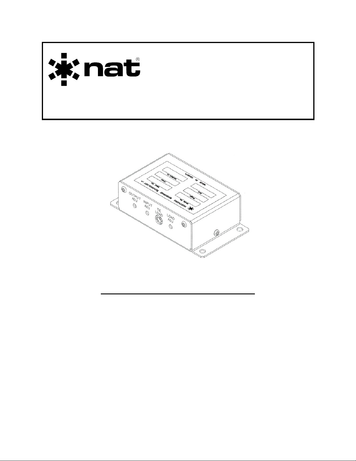
AA36-ECF
Tie Line Adapter
INSTALLATION AND OPERATION MANUAL
REV
Northern Airborne Technology Ltd.
Copyright 2003 by Northern Airborne Technology
4.00 December 5, 2003
1925 Kirschner Road
Kelowna, BC, Canada.
V1Y 4N7
Telephone (250) 763-2232
Facsimile (250) 762-3374
CONFIDENTIAL AND PROPRIETARY TO NORTHERN AIRBORNE TECHNOLOGY LTD.
Page 2

Page 3

SM42 Rev. 4.00 AA36-ECF Tie Line Manual
Periodically NAT will release manual amendments. In order to maintain the most
accurate and up to date manual these amendments should be carried out immediately
upon receipt and recorded on the following amendment record.
AMENDMENT RECORD
Amendment
Number
Amendment
Date
Section(s)
Changed
Date
Entered
Entered By
Insert any Amendment Instruction sheets after this page.
Dec 5, 2003 Page ii
ENG-FORM: 820-0109.DOT
CONFIDENTIAL AND PROPRIETARY TO NORTHERN AIRBORNE TECHNOLOGY LTD.
Page 4

Page 5

SM42 Rev. 4.00 AA36-ECF Tie Line Manual
Table of Contents
Section Title Page
1.0 Description
1.1 Introduction 1-1
1.2 Purpose of Equipment 1-1
1.3 Features 1-1
1.4 Specifications 1-1
1.4.1 Electrical Specifications 1-1
1.4.2 Physical Specifications 1-2
1.4.3 Environmental Specifications 1-2
2.0 Installation
2.1 Introduction 2-1
2.2 Unpacking and Inspection 2-1
2.2.1 Warranty 2-1
2.3 Installation Procedures 2-1
2.3.1 Warnings 2-1
2.3.2 Cautions 2-2
2.3.3 Cabling and Wiring 2-2
2.3.4 Setting NAT ICS TIE Output 2-2
2.3.5 Setting ICS OUT 2-2
2.3.6 ICS Tie Loading 2-3
2.3.7 PAX Mute Function 2-3
2.3.8 Post-Installation Checks 2-3
2.4 Continued Airworthiness 2-4
2.5 Accessories Required But Not Supplied 2-4
2.6 Installation Drawings 2-4
3.0 Operation
3.1 Introduction 3-1
3.2 General 3-1
3.3 Configuration 3-1
Dec 5, 2003 Page iii
ENG-FORM: 820-0109.DOT
CONFIDENTIAL AND PROPRIETARY TO NORTHERN AIRBORNE TECHNOLOGY LTD.
Page 6

Page 7

SM42 Rev. 4.00 AA36-ECF Tie Line Adapter Manual
Section 1.0 Description
1.1 Introduction
This manual contains information on the AA36-ECF Tie Line Adapter. All derivatives
will be covered by manual supplements, which can be obtained from NAT as required.
Information in this section consists of purpose of equipment, features and specifications.
1.2 Purpose of Equipment
The AA36-ECF interfaces a NAT ICS tie line to non-bidirectional tie line intercom
systems.
1.3 Features
The AA36-ECF is a remote bulkhead mounted unit. The input signal level is adjustable
to allow correct NAT ICS tie output levels. An internal switch provides selection to
different tie line load impedances. Allowance is made for an external switch to disable
the input and output to provide the pilot with a mute PAX conference function.
1.4 Specifications
1.4.1 Electrical Specifications
Power Supply
Normal Operating Conditions: +28 Vdc @ 110 mA max.
Operating voltages:
Nominal +27.5 Vdc
Maximum +30.3 Vdc
Minimum +24.8Vdc
Emergency +20.0 Vdc
Input Signals
ICS input:
Signal Level 500 mVrms
Impedance 4200 Ω ±10%
Adjust Trimpot 40 dB of range
Freq. response <3 dB from 350 Hz to 6000 Hz
Distortion <1% @ rated output
Dec 5, 2003 Page 1-1
ENG-FORM: 800-0107.DOT
CONFIDENTIAL AND PROPRIETARY TO NORTHERN AIRBORNE TECHNOLOGY LTD.
Page 8

AA36-ECF Tie Line Adapter Manual SM42 Rev. 4.00
Output Signal
ICS output:
Rated Level 500 mVrms into 5 kΩ
Freq. response <3 dB from 350 Hz to 6000 Hz
Distortion <10% @ rated output
Noise Level >60 dB down from rated output (without signal)
Isolation from ICS Input >35 dB
Adjust Trimpot 40 dB of range
Bi-directional Signals
NAT ICS Tie Line:
Signal Level 340 mVrms
Input impedance 1800 Ω ±10%
Output Impedance 600 Ω
Freq. response <3 dB from 350 Hz to 6000 Hz
Distortion <10 % @ rated output.
1.4.2 Physical Specifications
Height 1.25" (31.75 mm)
Depth 2.48" (62.99 mm) not including connector
Width 4.50" (114.30 mm) including flanges
3.50" (88.90 mm) excluding flanges
Weight 0.41 lbs (186 g)
Mounting Remote bulkhead mount: 4 x 10-32 screws.
Material/Finish Aluminum chassis and cover with chromate
conversion finish
Connectors 25-pin filtered male D-sub connector with jackposts
1.4.3 Environmental Specifications
Temperatures:
Operating -20° C to +55° C
Survival -55° C to +85° C
Altitude 35,000 ft.
Humidity 95%
Shock DO-160C Cat. M/N
Qualification:DO-160D Env. Cat. A1D1-XXB[(SBM)(UF)]XXXXXXXXXXX[UUX]MXXXX
End of section 1.0
Page 1-2 Dec 5, 2003
ENG-FORM: 800-0107.DOT
CONFIDENTIAL AND PROPRIETARY TO NORTHERN AIRBORNE TECHNOLOGY LTD.
Page 9

SM42 Rev. 4.00 AA36-ECF Tie Line Manual
Section 2.0 Installation
2.1 Introduction
Information in this section consists of unpacking and inspection procedures, installation
procedures, post-installation checks, and installation drawings.
2.2 Unpacking and Inspection
Unpack the equipment carefully and locate the warranty card. Inspect the unit visually
for damage due to shipping and report all such claims immediately to the carrier
involved. Note that each unit should have the following:
- AA36-ECF Tie Line Adapter
- Warranty Card
- Release certification
Verify that all items are present before proceeding and report any shortage immediately
to your supplier.
2.2.1 Warranty
Complete the warranty card information and send it to NAT when the installation is
complete. If you fail to complete the warranty card, the warranty will be activated on
date of shipment from NAT.
Note: An appropriately rated facility, e.g. Certified Aircraft Repair Station, must install
this equipment in accordance with applicable regulations. NAT Ltd’s warranty is
not valid unless the equipment is installed by an authorized NAT Dealer. Failure
to follow any of the installation instructions, or installation by a non-certified
individual or agency will void the warranty, and may result in a non-airworthy
installation.
2.3 Installation Procedures
2.3.1 Warnings
Do not bundle any lines from this unit with transmitter coax lines. Do not bundle any
audio or DC power lines from this unit with 400 Hz synchro wiring or AC power lines. Do
not position this unit or wiring from this unit next to any device with a strong alternating
magnetic field such as an inverter, or significant audio interference will result.
Dec 5, 2003 Page 2-1
ENG-FORM: 805-0106.DOT
CONFIDENTIAL AND PROPRIETARY TO NORTHERN AIRBORNE TECHNOLOGY LTD.
Page 10

AA36-ECF Tie Line Manual SM42 Rev. 4.00
2.3.2 Cautions
⇒ In all installations, use shielded cable exactly as shown and ground as indicated.
Significant ground loop and noise problems may result from not following these
guidelines.
⇒ Use caution when routing ICS tie line wiring as they use low level signals and are
prone to coupling from other sources.
Do not take a ground from the front panel or similar location that shares a ground return
with a turn and bank, horizon or other motor driven instrument. This may cause the unit
to pick up the sound of the motor as ground loop interference.
2.3.3 Cabling and Wiring
All unshielded wire should be MIL-W-22759 or equivalent. For shielded wire
applications, use Tefzel MIL-C-27500 shielded wire with solder sleeves (for shield
terminations) to make the most compact and easily terminated interconnect. Follow the
wiring diagrams in Section 2.6 as required.
Allow 3 inches from the end of the wire to the shield termination to allow the hood to be
easily installed. Note that the hood is a ‘clamshell’ hood, and is installed after the wiring
is complete.
All wiring should be at least 22 AWG, except power and ground lines, which should be
at least 20 AWG. Ensure that all ground connections are clean and well secured.
To prevent system failure or inadequate equipment protection, supply power from a
separate 1.0 A breaker or fuse, not connected to any other source.
2.3.4 Setting NAT ICS TIE Output
The mic signal from the Audio Controller to the AA36-ECF ICS IN is expected to be
approximately 500 mVrms.
The INPUT ADJ trimpot is factory set to provide 340 mV RMS ±10% on the NAT ICS
TIE line, but can be adjusted to give the desired output.
2.3.5 Setting ICS OUT
The signal level measured on the ICS tie line from the NAT audio controller/intercom
system is typically 340 mVrms, which is fed into the NAT ICS TIE on the AA36-ECF.
The OUTPUT ADJ trimpot on the AA36-ECF is factory set to provide 500 mVrms ±10%
signal at ICS OUT, measured across a 5 kOhm load, but can be adjusted to give the
desired output.
Page 2-2 Dec 5, 2003
ENG-FORM: 805-0106.DOT
CONFIDENTIAL AND PROPRIETARY TO NORTHERN AIRBORNE TECHNOLOGY LTD.
Page 11

SM42 Rev. 4.00 AA36-ECF Tie Line Manual
2.3.6 ICS Tie Loading
The TIE LOAD switch and LOAD ADJ trimpot are used to match the AA36-ECF with up
to four NAT ICS tie lines.
The TIE LOAD switch is set as follows:
Number of NAT ICS Tie Lines TIE LOAD Switch Position
1 Tie Line 1
2 Tie Lines 2
3 Tie Lines 3
4 Tie Lines 0
The LOAD ADJ trimpot is used for fine adjustment to match the AA36-ECF to the NAT
ICS Tie Lines.
With the TIE LOAD switch set to the desired setting (see table above), adjust the setting
of the LOAD ADJ trimpot so that injecting a 500 mV signal at the ICS IN input gives a
minimum signal across a 5 kOhm load at the ICS OUT output.
2.3.7 PAX Mute Function
The AA36-ECF can be equipped with an external switch to mute all ICS signals if
desired.
If the AA36-ECF is configured with the PAX Mute Function switch, verify its operation by
ensuring that there is no ICS audio in or out of the AA36-ECF when the switch is
enabled.
2.3.8 Post-Installation Checks
2.3.8.1 Voltage/Resistance Checks
Do not attach the AA36-ECF until the following conditions are met.
Check the following:
a) P101 pin <1> for +28 Vdc relative to ground.
b) P101 pin <14> for continuity to ground (less than 0.5 Ω).
c) P101 pin <4> for continuity to ground (less than 0.5 Ω) when the external PAX
Mute switch is closed (see section 2.3.7 above).
Upon satisfactory completion of all performance checks, make the required log
entries and complete the necessary Regulatory Agency paperwork before
releasing the aircraft for service.
Dec 5, 2003 Page 2-3
ENG-FORM: 805-0106.DOT
CONFIDENTIAL AND PROPRIETARY TO NORTHERN AIRBORNE TECHNOLOGY LTD.
Page 12

AA36-ECF Tie Line Manual SM42 Rev. 4.00
2.4 Continued Airworthiness
Maintenance of the AA36-ECF is ‘on condition’ only. Periodic maintenance of this
product is not required.
2.5 Accessories Required But Not Supplied
Installation kit p/n AA36-IKC (crimp) is required to complete the installation. Each kit
consists of the following:
AA36-IKC 25-pin D-min Female Crimp Kit (NAT Part No. D25SL-IKC)
Quantity Description NAT Part #
1 D-min 25 Socket Housing 20-21-025
25 MS Crimp Socket 20-26-901
1* Jack Screw Set 20-27-002
1* Lock Clip Set 20-27-004
1 25 Pin Connector Hood 20-29-026
* Use as required.
2.6 Installation Drawings
DRAWING REV. DESCRIPTION TYPE
AA36\ECF\403-0 1.00 ICS TIE Line Adapter Interconnect
AA36\ECF\405-0 1.00 ICS TIE Line Adapter Connector Map
AA36\ECF\922-0 1.00 ICS TIE Line Adapter Mechanical installation
Section 2.0 ends after these Drawings
Page 2-4 Dec 5, 2003
ENG-FORM: 805-0106.DOT
CONFIDENTIAL AND PROPRIETARY TO NORTHERN AIRBORNE TECHNOLOGY LTD.
Page 13

Page 14

Page 15

Page 16

Page 17

Page 18

Page 19

SM42 Rev. 4.00 AA36-ECF Tie Line Adapter Manual
Section 3.0 Operation
3.1 Introduction
Information in this section consists of the functional and operational procedures for the
AA36-ECF Tie Line Adapter.
3.2 General
The AA36-ECF interfaces a NAT ICS tie line to non-bidirectional tie line intercom
systems.
3.3 Configuration
The AA36-ECF Tie Line Adapter has no normal user operational aspects. During
installation, or if the unit has been exchanged, it may be a requirement to change
internal adjustments. This should be done ONLY BY FULLY QUALIFIED
PERSONNEL.
End of section 3.0
Dec 5, 2003 Page 3-1
ENG-FORM: 806-0106.DOT
CONFIDENTIAL AND PROPRIETARY TO NORTHERN AIRBORNE TECHNOLOGY LTD.
Page 20

 Loading...